So here is the problem, I saw that the sidemarkers should be on when the lights are on. My front sidemarkers are working only when switched left or right turn signal. The bulbs are fine. I saw there are 2 wires each side, one black(or dark grey) and light blue/dark blue that is giving the + signal. I'm not sure if they worked when I bought the car, but the reason that they are not working could be that it was illegal here in Europe and somebody turned it of. Can somebody help me where to check that, how to connect them back? It's an 88GT V6
Any suggestion, wiring schemes etc. would be helpful
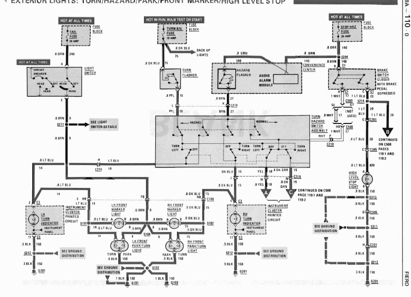
Could you help me, if I see it right, the Lt and Dk Blue wires are going from the instrument cluster? Where could they be disconnected that the park light aren't working, but the turn light is?
Make sure the bulbs used are still double filament.....and the socket has not be altered. There should be 2 contact points at the bottom of the park/turn socket.
Originally posted by Gall757: Make sure the bulbs used are still double filament.....and the socket has not be altered. There should be 2 contact points at the bottom of the park/turn socket.
You're probably thinking about the front turn signals... the side markers are simple #197 style bulbs with a single filament that turns on and off to blink.
You're probably thinking about the front turn signals... the side markers are simple #197 style bulbs with a single filament that turns on and off to blink.
This is the second time I have heard it is illegal to have rear side markers in Europe, whats the reason out of curiosity?
Years that was the car imported was almost everything illegal, including the side markers or the 3rd brake light (my Firebird 94' has the cover, but without socket)... Nowadays we have Volvo's that are the only EU cars produced that have side markers
Originally posted by rd1: So here is the problem, I saw that the sidemarkers should be on when the lights are on. My front sidemarkers are working only when switched left or right turn signal. The bulbs are fine. I saw there are 2 wires each side, one black(or dark grey) and light blue/dark blue that is giving the + signal. I'm not sure if they worked when I bought the car, but the reason that they are not working could be that it was illegal here in Europe and somebody turned it of. Can somebody help me where to check that, how to connect them back? It's an 88GT V6
Any suggestion, wiring schemes etc. would be helpful
Yes, If car was imported from US/Canada... (Car was made for those markets) Car was modify so pass local laws. The mod is simple. They likely cut blue wires and ground/earth the bulb side. Find the cut ends and splice back.
USDOT rules requires Fiero front markers to blink when parking lights are on or off because Front bulb setup buried in the car's "bumper." OE Fiero front marker for US/Canada use wire as image above and shown how they work on LED Marker Light
You would need to check what is legal for you before you change light setup. Croatia just joined EU last year.
I Think, Current EU rules for import from US is... OE Front Markers on when parking lamps are on. You add a light between front wheel and door that blinks when turn light is active.
Don't know rear marker rules. If light isn't allowed then just pull the bulb. Use Silicon grease on the socket to keep out water.
------------------ Dr. Ian Malcolm: Yeah, but your scientists were so preoccupied with whether or not they could, they didn't stop to think if they should. (Jurassic Park)
Yes, If car was imported from US/Canada... (Car was made for those markets) Car was modify so pass local laws. The mod is simple. They likely cut blue wires and ground/earth the bulb side. Find the cut ends and splice back.
USDOT rules requires Fiero front markers to blink when parking lights are on or off because Front bulb setup buried in the car's "bumper." OE Fiero front marker for US/Canada use wire as image above and shown how they work on LED Marker Light
You would need to check what is legal for you before you change light setup. Croatia just joined EU last year.
I Think, Current EU rules for import from US is... OE Front Markers on when parking lamps are on. You add a light between front wheel and door that blinks when turn light is active.
Don't know rear marker rules. If light isn't allowed then just pull the bulb. Use Silicon grease on the socket to keep out water.
Thx man, that is a good advice, but I don't understand one thing, is that side marker made to blink as a turn signal or is it just a marker light? When yes, where or what turns the + signal of and makes it to blink?
P.S. Your site is saved to my favorites for a long time, big + for that!
When you only turn on the park lights, power flows from the tail fuse through the switch, through the light and then grounds through one of the filaments in the front park/turn lights.
To understand how the side marker blinks, you must understand that there are two ways to make a light turn off. The first is to withdraw power from the light bulb. The second way is to feed 12V to both sides of the light bulb. This second way is how the Fiero side markers blink. When you turn on the flasher while the park lights are on, 12 volts is fed to one side of the side marker bulb as above, but the other terminal of the side marker bulb is also fed 12V from the turn b/u fuse through the flasher, through the turn/haz switch assy, to the dash indicator and to the "ground" side of the side marker light. When the flasher unit intermittently turns the power off from the turn b/u fuse, the side marker turns back on again because one side of the bulb is still being fed 12V from the tail fuse.
So here is the problem, I saw that the sidemarkers should be on when the lights are on. My front sidemarkers are working only when switched left or right turn signal. The bulbs are fine. I saw there are 2 wires each side, one black(or dark grey) and light blue/dark blue that is giving the + signal. I'm not sure if they worked when I bought the car, but the reason that they are not working could be that it was illegal here in Europe and somebody turned it of. Can somebody help me where to check that, how to connect them back? It's an 88GT V6
Any suggestion, wiring schemes etc. would be helpful
If they flash:
1) bulbs are good 2) sockets are good
If they don't turn on with the light switch, only 2 things can affect that:
1) light switch bad - not likely 2) wire bad/disconnected from the light switch
Check you have a wire connected to terminal E on the light switch (probably). Then check the C100 plug (big plug, front compartment going through the front bulkhead) Pin F10. The brown wire that is connected to C100 pin F10 is probably cut either at the plug or someplace down the line until the 'junction' where it meets up with the other 4 brown wire for each socket.
You can find that drawing posted above on page: 8A-110-01 The position of the C100 plug is on page (bottom right): 8A-201-10 C100 pinout in on page: 8A-202-01
[This message has been edited by Mickey_Moose (edited 08-01-2014).]
If they don't turn on with the light switch, only 2 things can affect that:
1) light switch bad - not likely 2) wire bad/disconnected from the light switch
Check you have a wire connected to terminal E on the light switch (probably). Then check the C100 plug (big plug, front compartment going through the front bulkhead) Pin F10. The brown wire that is connected to C100 pin F10 is probably cut either at the plug or someplace down the line until the 'junction' where it meets up with the other 4 brown wire for each socket.
You can find that drawing posted above on page: 8A-110-01 The position of the C100 plug is on page (bottom right): 8A-201-10 C100 pinout in on page: 8A-202-01
I can't find the sections you mentioned above, neither the pages or the c100 plug
I can't find the sections you mentioned above, neither the pages or the c100 plug
Just go to the pages (ex: 8A-110-01) I posted and the info is there. The page numbers are at the top of most pages (some of the pages are displayed sideways in the file, the number is on the right most side (or at the top on vertical pages)). Look under the "Electrical Diagnosis" bookmark for section 8A. The first part of the page number is the section.
Solved the problem, you were right, the black wires/dark grey were grounded, found the wires that have a constant + and now it's working.
Another question, is it hard to rewire the sidemarkers, I would love to see them lighting even when the lights are off. Can they be bricked somehow in the fuse box?
It's possible but it would be somewhat involved because you'd have to snip the brown wires leading to all four side markers and splice new wires to them that would have to be routed from the front and rear quarters, into the cabin, and then to a fuse that's hot while the ignition switch is in run. Running the wires would be the most difficult part since there are blank fuse slots in the panel that could easily be used for power.
Very good, thx... But aren't the sidemarkers fused, if yes, then it would have to be easier to supply them in the fusebox. If not, then it's the only way, but I don't like to add new wires into the cabin
Perhaps you've misunderstood how the original wiring is laid out. There is only one brown wire that leads from the light switch all the way to the back of the car. Near the rear bumper, that one brown wire branches out into a huge splice where 6 other wires take the power to individual RH park/marker lights and the license plate lights and a 7th wire leads to another splice located on the LH side of the bumper where four more wires run to the individual LH park/marker lights.
Since there aren't individual wires for each of these lights that run all the way to the fuse panel, the only way to separate the rear side markers from the rest of the circuit is to cut the brown wires near the rear side marker lights, splice them together using an extension, and run an additional single wire from that splice all the way to the fuse panel.
The same thing has to be done in the front.
Once you've got your two wires (one for the front and one for the rear) near the fuse panel, you can crimp on a simple blade style connector to both wires, and plug the blade into one of the slots marked IGN (see photo, disregard the slots marked BAT). Those IGN ports are fused through the 10 Amp Gages Fuse and will be hot whenever the ignition switch is in RUN, so the new circuit will be protected.


 They are indeed 194's.


