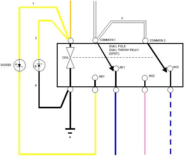
They were discontinued and so far no one has taken up the torch to start making aftermarket ones. For now, the only recourse is to find a used one, or make one yourself out of a dual pole dual throw (DPDT) relay and a pair of diodes. Here's a quick schematic of how to make one:
where:
NO1 = normally open terminal for pole 1 NC1 = normall closed terminal for pole 1 NO2 = normally open terminal for pole 2 NC2 = normall closed terminal for pole 2
And you would have to add the wires marked 1 through 4 whereas the remaining wires are OEM.
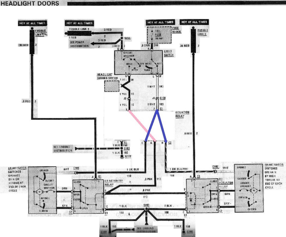
I sat down this afternoon with the diagram from the fsm and drew up the same drawing as you have there. I was in the process of hooking it up that way when I asked myself a question. What exactly is the purpose of this relay? After staring at this relay for quite sometime I can't for the life of me figure out why GM felt it was necisary. I made myself some jumpers with spade connectors to go into the plugs the isolation relay goes into to connect the white wire to the pink wire and the yellow wire to the blue and blue/white. The headlights now work Id be curious as to why (in technical terms) anyone thinks GM felt this relay was necessary. The switch still carries the current when the lights are going down and the headlight relays carry the current when they are going up with or without the isolation relay. The only possible negative outcome I can think of is if there were a very specific failure of the headlight switch the isolation relay would keep the tail light fuse from blowing. Maybe Im missing something.
I can't see why that could have anything to do with the absence of the relay. When the headlights are in the down position with the switch off the relay simply connects the yellow wire to the blue, and blue/white wires. Nothing more nothing less. If your battery was dieing due to the headlight motors it would most likely be the limit switch not functioning properly. That would also be likely to make the motor quit in fairly short order.
[This message has been edited by gtjoe (edited 04-07-2012).]
I made myself some jumpers to connect the white wire to the pink wire and the yellow wire to the blue and blue/white.
If you did it this way then with the light switch OFF, power from the Tail Fuse would run through the switch down the white wire, through your jumper, down the pink wire which would energize the motor relays and cause the headlight pods to open. I take it therefore that you meant you jumped the white wire to the blue and blue/white wire, and jumped the yellow wire to the pink wire instead, like this:
I can't see why this would present any problems. At first I thought perhaps the rating of the contacts in the light switch might not be up to snuff, but this bypass circuit doesn't change the routing of the current at all. Also, I can't see how this would drain the battery either as Niterrorz said (well, as long as you wired your car as per my diagram and not as you actually said you did!) Unless there's something obvious that both of us have missed, I would agree that the iso relay doesn't appear to be needed at all. I give you a "+" for thinking this through.
[This message has been edited by Bloozberry (edited 04-08-2012).]
I know it doesn't help anyone at the moment, but I've been told of and am checking out a source for the isolation relays. Seems someone may be making them for other than automotive applications.
If you did it this way then with the light switch OFF, power from the Tail Fuse would run through the switch down the white wire, through your jumper, down the pink wire which would energize the motor relays and cause the headlight pods to open. I take it therefore that you meant you jumped the white wire to the blue and blue/white wire, and jumped the yellow wire to the pink wire instead, like this:
I can't see why this would present any problems. At first I thought perhaps the rating of the contacts in the light switch might not be up to snuff, but this bypass circuit doesn't change the routing of the current at all. Also, I can't see how this would drain the battery either as Niterrorz said (well, as long as you wired your car as per my diagram and not as you actually said you did!) Unless there's something obvious that both of us have missed, I would agree that the iso relay doesn't appear to be needed at all. I give you a "+" for thinking this through.
You are correct I switched the colors on my post. The color pinout is as you described.
GM use the relay to protect headlight switch. All the Diodes are as a surge protected item. you can run the motors without the relay but the headlight switch may fry. And most likely it will die on the highway...
the motors draw more amps when the doors are open. to open the motors have to fight gravity and the door springs. When doors are closed, the gravity and door Springs for help the motors to close.
Bloozberry your schematic looks correct. both diodes arts surge protector the car's electrical system. Diodes B blocks the surge from relay coil itself. Diode A blocks the surge from the motors. Diodes in 1N400x class will work. www.diodes.com/datasheets/ds28002.pdf the motors surge could be high, use 1N4007. (motors and AC clutch can generate 400-700 volts surge when power is cut.)
I suggest you use in automotive part for the relay. Most car parts are made with heavy duty in mind.
------------------ Dr. Ian Malcolm: Yeah, but your scientists were so preoccupied with whether or not they could, they didn't stop to think if they should. (Jurassic Park)
GM use the relay to protect headlight switch. All the Diodes are as a surge protected item. you can run the motors without the relay but the headlight switch may fry. And most likely it will die on the highway...
the motors draw more amps when the doors are open. to open the motors have to fight gravity and the door springs. When doors are closed, the gravity and door Springs for help the motors to close.
Bloozberry your schematic looks correct. both diodes arts surge protector the car's electrical system. Diodes B blocks the surge from relay coil itself. Diode A blocks the surge from the motors. Diodes in 1N400x class will work. www.diodes.com/datasheets/ds28002.pdf the motors surge could be high, use 1N4007. (motors and AC clutch can generate 400-700 volts surge when power is cut.)
I suggest you use in automotive part for the relay. Most car parts are made with heavy duty in mind.
The surge from the headlights opening is absorbed by the headlight relays, the power to open the headlights is not drawn through the isolation relay. One of the diodes in the isolation relay is to keep the relay from chattering. The other passes power from the input to the relay coil to the contacts to pass to the pink wire. The headlight switch on opening is isolated from the motor sure regardless of whether the isolation relay is in the circuit or not. The closing circuit is electrically unchanged.
I know it doesn't help anyone at the moment, but I've been told of and am checking out a source for the isolation relays. Seems someone may be making them for other than automotive applications.
If you find a source please share. I plan on replacing the jumpers with a isolation relay when I can find one. If nothing else for aesthetics.
Originally posted by gtjoe: The surge from the headlights opening is absorbed by the headlight relays, the power to open the headlights is not drawn through the isolation relay. One of the diodes in the isolation relay is to keep the relay from chattering. The other passes power from the input to the relay coil to the contacts to pass to the pink wire. The headlight switch on opening is isolated from the motor sure regardless of whether the isolation relay is in the circuit or not. The closing circuit is electrically unchanged.
Sorry... yes, Open power comes from Fuse Links....
If I can't solve my problem soon I think I'm going to rewire the darn thing and use a heavy duty momentary DPDT center off toggle switch ditch all the relays. I don't mind hold a toggle a few seconds until the lights are all the up or down.
What exactly is the purpose of this relay? After staring at this relay for quite sometime I can't for the life of me figure out why GM felt it was necisary.
Good question. Assuming that the headlight switch is working correctly, the isolation relay's only purpose is to isolate the two headlight motor "down" circuits from each other when the headlight switch is in the "headlight" position. This would protect against some possible limit switch malfunctions.
The isolation relay also provides secondary protection against the headlight motor "up" and "down" circuits being energized simultaneously.
quote
Originally posted by theogre:
All the Diodes are as a surge protected item.
... both diodes arts surge protector the car's electrical system ,,, Diode A blocks the surge from the motors. Diodes in 1N400x class will work.
Slight correction. Diode A is not there for surge suppression. its purpose is to provide a current path to the headlight "Actuator Relay" coils when the headlight switch is in the "Headlight" position ... and a diode seems unnecessary for even that purpose.
FWIW, the 86 FSM shows that the RH actuator relay includes a surge suppression diode, while the LH actuator relay does not. I wonder if that's actually correct. It would have saved GM a few cents in manufacturing cost at the expense of using two different relay types rather than one. It would be easy enough to add a third external diode to guarantee surge suppression in the actuator relay coil circuit.
Diode A should be chosen to carry the combined current of the two actuator relay coils plus a safety margin. The 1N400x series diodes are all rated at only 1 amp max continuous forward current; the peak reverse voltage of even the 1N4001 (50 volts) should be fine for an automotive application. Anybody know the DC resistance of each of the actuator relay coils?
[This message has been edited by Marvin McInnis (edited 09-17-2012).]
They were discontinued and so far no one has taken up the torch to start making aftermarket ones. For now, the only recourse is to find a used one, or make one yourself out of a dual pole dual throw (DPDT) relay and a pair of diodes. Here's a quick schematic of how to make one:
where:
NO1 = normally open terminal for pole 1 NC1 = normall closed terminal for pole 1 NO2 = normally open terminal for pole 2 NC2 = normall closed terminal for pole 2
And you would have to add the wires marked 1 through 4 whereas the remaining wires are OEM.
This works! 86 Firebird --> Lights turn on, would not go up, manually crank them up, turn switch off, motors kick on and lower headlights. Purchased parts at RadioShack and wired this up. Removed old relay and plugged this into male connector and worked on the first try. I have looked everywhere for parts....this is the most useful diagram and information out there. Thanks!