I am building a custom dash and want to use different heat & A\C controls but all the custom dashes I found when I did a search still had the stock Fiero heat controls. I saw a couple of posts that said they where going to use something different but when they showed pictures of the finished dash it still had the stock controller in it. If anyone has a non-stock installed and working heat &A\C controller, please post pictures and tell us how you did it.
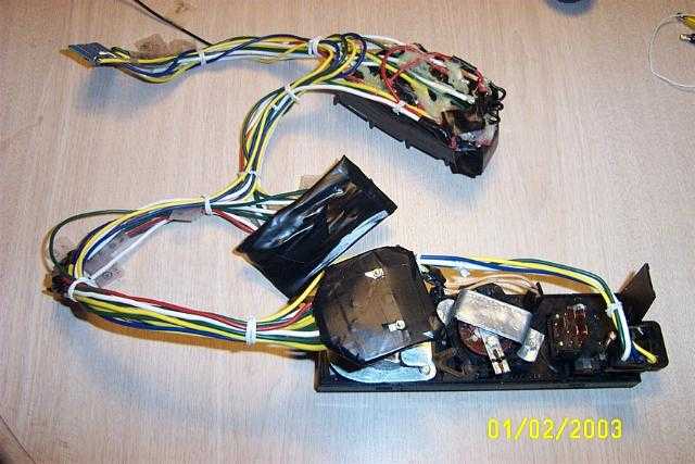
Swapping A/C controls is not easy on the Fiero because most cars either use vacuum or all electric. There aren't many cars that uses electric for the mode control and cable for the temperature control. One solution is to convert the mode control of the firebird to electric by adding a multi-position switch in place of the vacuum switch. It's not difficult but tedious to build.
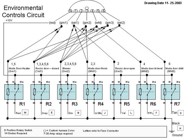
This is an early prototype of the setup.
Check my webpage or PM me if you have more quesitons.
Id like to do the same thing, and it seems that all you really need is a heater control that uses electronics for the modes and a tension cable for the temperature control. Does anybody know of other cars besides the Camaro that have this? it seems like there should be a lot of them.
IP: Logged
11:20 PM
Jan 12th, 2005
jscott1 Member
Posts: 21676 From: Houston, TX , USA Registered: Dec 2001
all you really need is a heater control that uses electronics for the modes and a tension cable for the temperature control. Does anybody know of other cars besides the Camaro that have this? it seems like there should be a lot of them.
The Camaro does not use electronics for the mode control. That's the whole point of the conversion I was talking about earlier. Just today I searched all of eBay. (about 200 different types) for any car that would have the right configuration and I came up empty. Most cars use vacuum or all electronics.
The Fiero was pretty unique in that it's electric and cable. Another way would be to convert the Fiero to all electronic and elliminate the cable altogether.
IP: Logged
01:53 AM
Christine Member
Posts: 1052 From: Denver, Colorado Registered: Jan 2003
The Fiero was pretty unique in that it's electric and cable. Another way would be to convert the Fiero to all electronic and elliminate the cable altogether.
That might work.
Thanks, Christine
IP: Logged
12:52 PM
bubbajoexxx Member
Posts: 1630 From: Ontario Canada Registered: Aug 2003
you can use the electronic controlls from the 84 to 87 buicks and olds cars it is touch contoll no cables you need only to add one controller for the cable and you will have a system that is temp controlled with the termostat in the controller no fan switch use as well as it is all in one unit just make sure you get it with the harness
you can use the electronic controlls from the 84 to 87 buicks and olds cars it is touch contoll no cables
Can you tell me what models Buick and Olds came with this? I have been searching for a suitable donor for an all electronic system. I'm not happy with the cable on mine.
IP: Logged
08:03 PM
Mar 28th, 2005
Phantom-Fiero Member
Posts: 416 From: Newport News, VA USA Registered: Jun 2002
I was / is / are / etc planning on the 3000GT control. It will be a pain in the butt to put it mildly. The same for any all-electronic control, you'll need to convert the cable operated temperature door to electric, then go from there. The Buick all-electronic one looks to be the easiest to convert (have one of those from my donor car, had it running outside the car by itself), the Mitsubishi one is tied into the ECM in a couple places but I haven't gotten into it enough to figure that part out. I think the modded Firebird one is a cool way to go, without having to redesign / modify the Fiero setup. There *is* someone out there with a 3000GT control in a "Fiero", sort of... I saw a picture of a very nicely done Lambo kit car that had the 3000GT control working. Looked niice.. So it is possible..
IP: Logged
11:45 PM
PFF
System Bot
Apr 2nd, 2005
Riceburner98 Member
Posts: 2179 From: Natick, Ma, USA Registered: Apr 2002
(First of all, AAAAGGGHHHH! I spent 20 minutes entering a longer post with more detail, then it kicked me back with an error message, and the post was GONE! Argh...) Uh yeah. Anyway, a bump / update of sorts... I created a spreadsheet of Fiero AC control wires and info, kind of a "how-to" (or at least a start) to convert whatever AC controller to operate the Fiero system. Link: http://home.comcast.net/~riceburner98/functions.xls I mainly was doing it to see if I could make a better controller for the Ferrari kit car guys, but the thread seems to have died over on that forum. (they're talking of using Ford or other (IMO) fugly GM systems, nobody seems to have a "real" looking Ferrari style one available) But this should help anyone looking to swap in a non-Fiero manual controller. All you need is to be able to mount a 1-layer, 6-position switch behind the mode knob of your choice. (or a 7 or 8 pos. would work too, just have some "duplicate" modes...) This requres no relays for the mode switching, as the mode doors and control relays only use about .3A. (just make sure the switch can handle that or more! Most common ones can..) It's also configured so that you push the mode switch (or another seperate button, I know some GM's already have that button) to activate the AC compressor, and a button for the recirculate door. I always liked having control over when the AC turns on or when the air recirculates. (sometimes like to quickly heat up the car by recirculating hot air, without AC!) So this works out perfectly for me. Here's a pic of the F355 control, and the nearly identical F550 control for reference to what I'm babbling about:
Well, yeah... Hope the info can help someone!
IP: Logged
01:38 AM
jscott1 Member
Posts: 21676 From: Houston, TX , USA Registered: Dec 2001
It's going to take me a while to figure out what you did, but it looks essentially the same as mine. Since mine works I assume I did it correctly
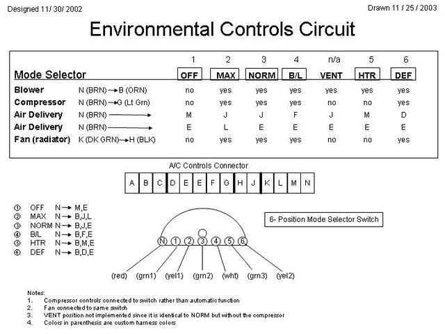
I used a one layer 6 position switch. The one thing I don't see in your description is I had to use a bunch of diodes to keep the signals from creating sneak circuits from the one layer switch. I'm not sure how you do that. Like you I preferred to have a switch for the A/C compressor, so I didn't implement the "VENT" position since it's identical to Normal but without the compressor. Excellent work you did figuring it out by the way.
And the reason I used the relays was not because of the current handling, it was to clean up the power going to the motors. After going through my logic circuit the voltages dropped maybe a volt or two. With the relays I could pump in a fresh 12V and be sure the doors will operate as designed. I could have used much smaller relays than the 30A ones except I got them real cheap.
My real goal is to replace that cable on the temperature door and make a fully electric system. I haven't been able to identify a donor for that application yet.
- Jonathan ]
[This message has been edited by jscott1 (edited 04-02-2005).]
IP: Logged
02:01 AM
Riceburner98 Member
Posts: 2179 From: Natick, Ma, USA Registered: Apr 2002
I kinda thought you did the diode thing.. That was how I started designing it first, but then realized (at least with the 355 style setup) I didn't even need more than 1 "layer". If you look at the "Wires activated (need 5-layer switch)" column, then compare it to the "Wires activated (need 1-layer switch + buttons)" column, you'll see that only 1 wire for each function in the 5-layer version is listed for the 1-wire version. (guess that makes sense, lol) Basically, "B" can be taken off because it's replaced by the "stop" or "off" button on the 355 control - it shuts off the power to the blower motor. That removes 1 layer. "G" is replaced by the seperate AC on / off switch, removing another layer. "E" and "L" are replaced by the "recirc" switch, which removes another layer. Then "K" needs to be inverted from the "G" line (relay or xistor?), as it's on only when the AC is on. So you end up just needing 1 wire for each mode. Example - for "Max", instead of needing to turn the blower on, turn the AC clutch on, turn the vents on, turn recirc. on and turn the radiator fan on, you just need to turn the vents on. Blower on/off is controlled by the "stop/off" switch, AC clutch and rad. fan is controlled by the "AC" switch, recirc. is controlled by the "recirc" switch. So by adding the other switches, you use only 1 switched "layer" for the mode doors, thereby eliminating the need for the diode isolation between functions. That assumes that you have a controller that will include those buttons. The AC switch being under the Mode switch will look trick, but may be slightly tricky. I found a switch that should work, just need to make the Mode knob float by about 1/8" or so. The first version I had on paper with all the diodes and relays was just getting out of control, so I figured there had to be a simpler way. The second thought was to keep the diodes and relays, but use reed relays instead. Plenty of current (I think?) and smaller.. Then I thought transistors would be good, but like you said, voltage drop comes in.. I may actually re-think my plans for using the automatic 3000GT control and hook up the F355/F550 one instead, it's simple and it's kinda growing on me... hehe.. As for electrifying the Fiero heat door control, I was looking suspiciously at the 3000GT or Buick control motors I have... I think they could be adapted to the shaft of the Fiero heater door, and they were already designed for the job with small size and built-in feedback pots. Just need a bit of micro-brains to control them. That was another thought - getting the "aut" on the F355 controls to work with some microcontrollers! I've so far convinced myself that's totally overkill for such a small interior... Just the "cool" factor!
IP: Logged
02:52 AM
RCR Member
Posts: 4452 From: Shelby Twp Mi Registered: Sep 2002
Excellent guys...Thanx for the heads up, Bob. This is going to come in handy when I get back to my GA HVAC. Now that the electronics is handled, what are you doing about the cable?
Bob
PS..I think I have a + for you here somewhere...Oh, there it is
[This message has been edited by RCR (edited 04-02-2005).]
IP: Logged
08:08 AM
Riceburner98 Member
Posts: 2179 From: Natick, Ma, USA Registered: Apr 2002
Now that the electronics is handled, what are you doing about the cable?
I talked to MrFixit58 about this; what I would really like to do is figure out what motor would be appropriate to use to drive the temp door. It would be awesome If I could use the same motor the Fiero uses for the mode doors, but I would need to figure out a way to make it stop in 10 or so intermediate stops. I haven't had time to think about that. RC motors is another way to go but they aren't cheap enough for my taste.
IP: Logged
02:06 PM
Riceburner98 Member
Posts: 2179 From: Natick, Ma, USA Registered: Apr 2002
Thanks linenoise! jscott -- do you have a picture handy of what the top of the Fiero heater box looks like - specifically where the shaft for the door comes out and the cable attaches? My Fiero has been retired for the weekend (50 miles from here) so I can't go check on mine... I have the 3000GT control motor in my hand right now, I'm going to see if I can figure out how to attach it to the Fiero shaft. "Worst" case, the 3000GT one already has an arm with a post on it, that could just be attached to the end of the Fiero cable to duplicate the sliding action of the original control. Using the internal feedback resistor, I can make a simple microcontroller circuit that would give you "infinite" control over the position of the door. With the arm on it now, the 3000GT motor has about a 1.5-1.75" throw, that should be plenty for the Fiero cable. The actual shaft looks like it turns about 95-100 degrees, if a direct coupler could be used to the Fiero shaft.. (how many degrees does the actual Fiero heat door move??) I love this stuff! Best part is, you can probably pull a 3000GT control motor from a junkyard for < $10. I can't remember how hard it was to pull as I got it over a year ago, but I remember all I had with me was a pair of locking pliers and a screwdriver.... Edit: Now that I've taken the motor apart and put some thought into it, you don't even need a microcontroller, just a simple comparator. The resistor range in the motor is approx 210 ohms -> 4.7k ohms, so all you'd need is a 5k variable resistor in place of the temperature knob, and you'd be all set. This is almost too easy! There's even an adjustable resistor in the motor, covered with a sticker from the outside, so you can adjust the inside resistance. It's like this motor was made to be modded! Man, I bet you could use this thing as a HUGE "super-servo" for a monster R/C model! I've got to go test the current requirements and see how much torque this thing puts out, but I'm betting it's huge given the reduction gears inside it. (the main reduction gear is metal, too) Woo! Too bad the range is only about 90 degrees though, most servos are more..
[This message has been edited by Riceburner98 (edited 04-02-2005).]
IP: Logged
04:34 PM
Riceburner98 Member
Posts: 2179 From: Natick, Ma, USA Registered: Apr 2002
I'm posting this as a reply instead of an edit just for a bump I guess... Testing shows: It takes 4 seconds for a maximum 1.75" throw with the existing arm, 15mA current draw while running (Low!!) and about 60mA max with me resisting it. I can stop the arm from moving, but it takes some good effort. (guessing about 15 pounds of pressure?) The thing doesn't even take 1/2 an amp to run when maxed out, so small relays or transistors can be tied to the comparator circuit to operate it. I'd probably hook up either a circuit breaker in-line with the power feed, or limit switches just to make sure the motor doesn't do bad things if it tries to go too far for a worst-case scenario. It doesn't have an internal "slip" clutch like I would have thought. Here's a picture of the unit, it's rather small, and I see no reason so far that it wouldn't work! The brackets in the pic actually make it look a bit bigger than it is -- without the brackets sticking out, it's 3" x 2" x 2" tall. The shaft the arm is attached to is .315" diameter, D-shaped with a screw hole, and sticks out .5". The post on the end of the arm is .155" diameter, .330" long with a circlip groove at the end. It has a .295" diam. x .295" long bushing on it now. Any thoughts jscott or mrfixit??? (edit: whipped up a prototype, but I can't test it in the Fiero 'cause it's unavailable... Plus need to finish the OpAmp circuit for the heater motor drive...)
[This message has been edited by Riceburner98 (edited 04-02-2005).]
IP: Logged
05:27 PM
jscott1 Member
Posts: 21676 From: Houston, TX , USA Registered: Dec 2001
Awesome find. I have a pic somewhere of the top of the heater box somewhere, I'll post it when I find it. If you can design that Comparator circuit I will be eternally grateful.
IP: Logged
08:56 PM
PFF
System Bot
Apr 11th, 2005
Riceburner98 Member
Posts: 2179 From: Natick, Ma, USA Registered: Apr 2002
Update I guess... Looks like it'll be a really tight fit for the Mitsubishi motor right on top of the box, connected directly to the shaft. I don't have the upper ductwork in my Fiero, but I can tell the motor would hit it if it's there. No problem, it would be easier to make a bracket and connect the existing cable end to the motor anyway, I really think that's the simplist solution. I also picked up a GM motor from a '96 Corsica (think most GM motors are the same, from what I've seen anyway) that would be a better fit directly on top of the heater box, have to take that one apart and play though. As for the circuit, I built it, and it works, but I'm not satisfied with it. For most of the range it's OK, but at the beginning and end it gets a little confused and the motor starts going back and forth rapidly, sometimes you can just hear the relays buzzing they're going so fast. I'm not too sure on the all-discrete parts approach, I personally prefer microcontrollers. Give them whatever input you want, and with a little code, the output can do whatever you want it to. So I think I'm going to take that approach, just need to sit down with the PIC programmer and figure it out. But the good news is, it will work.
IP: Logged
06:08 PM
jscott1 Member
Posts: 21676 From: Houston, TX , USA Registered: Dec 2001
Prepare the +'s then! LOL But I can't take the credit for this one, someone beat me to it... Who? Our good freindly GM engineers! Or possibly a company called CEI, that's what's embossed in the case.. What am I talking about? Well, that circuit that I just couldn't get right.. (because I *suck* at analog electronics!!!) GM was nice enough to figure it out, (Well, CEI -- they make all kinds of actuators: http://www.ceiltd.com/flatpack.htm ) and package it all nice and neatly into the AC control motor. That's right, all you need to make this motor work, is a variable resistor. Any variable resistor. The way they have it set up, with just 12v power applied, the motor is self-centering. The input to it is a voltage-divider, set to 1/2. Your input from whatever potentiometer you use sends that voltage closer to +12v or Gnd depending on which way you turn it. So you can use a 50k ohm resistor, or a 5k ohm resistor. At 1/2 revolution, either one is going to put out 6v, just different current levels. But this circuit doesn't care about current, just voltage. (I can actually make it move by touching +12v with one hand, and the input with the other. My body is 5 Meg ohms tonight) So all you do, is attach one end of your variable resistor / pot behind your heater control knob to +12v, the other to Gnd, and the center tap to the input of this thing. The electronics inside the motor take care of the rest. This motor turns almost exactly 90 degrees, and is definitely mountable on top of the heater box. All you need to do is make an adapter for the inside of the motor to connect it to the Fiero heater box shaft. The Fiero shaft is a D-shaped rod, and this AC motor has a ~ 1/2" "hollow" shaft. One half of the depth is splined, the other half has a "double-D" shaped hole. So what I would do is put this "hole" over a "greased up" bare Fiero shaft, and fill the hole with JB weld. When hardened, you'll have an adapter permanantly attached to the inside of the motor "hole", that can be slipped off the Fiero shaft. Just need to screw this motor to the top of the Fiero heater box, probably with some spacers to set it just right. The main output gear has a hard stop at each end of the travel, but they are set at more than 90 degrees, and the motor stops a good distance before it hits them. That said, you could cut the stops off, open the thing up, and rotate the main gear to match up to however the Fiero shaft has to sit. (so you're not stuck mounting the motor in any particular direction. You mount it how it fits, then adjust the gear to match the Fiero shaft / door) The sensing resistor inside the motor has a gear on it, that's how it connects to the main gear. So no matter where the main gear is, the little sensor resistor doesn't care, it only knows the 90 degree travel. (then again, if doing the JB weld thing, you just need to make sure the Fiero heater door is centered when the JB weld dries, don't even need to open the motor up..) This thing is PERFECT! I've been playing with it for like 5 minutes... Back and forth... Back and forth... LOL It's *TOO* easy! I'm just using a 5K ohm resistor I had lying around.. You want to use a *linear* resistor, not an "audio" or "logarithmic" one. Those kinds might have a wierd effect on it. I wouldn't go any lower than 5K ohms, to keep the current down low. (Just tried a 50K for giggles, with the same AWESOME results) So, I guess that just about covers it! If any of that didn't make sense, just let me know and I'll try to explain further. For reference, I got it out of a '96 Chevy Corsica / Beretta, it's the motor closest to the driver's feet on the heater box. Took 10 seconds to remove from the car once the lower dash cover panel is removed. (2) 5.5mm screws hold it to the box, but a 6mm socket at a bit of an angle will work in a pinch. You can see the motor and plug when the panel is removed. I'm sure this motor is used elsewhere, but that's what I got it from... The PN on it is 16124922 and it shows up NEW at GMpartsdirect for only $30!!.. Only 3 pins on the plug are used, so you can probably get away with not even buying the plug, just solder some wires right to the pins on the motor. So, who's going to be the first to try it in a Fiero?!?!
------------------ Bob Williams Multi-colored '86 Mutt, a work in progress! (3800SC running great! Fixed the bent roof, now I need an intercooler! Yeehaa!)
IP: Logged
08:35 PM
jscott1 Member
Posts: 21676 From: Houston, TX , USA Registered: Dec 2001
Bob...Any idea if this is in a vehicle, i.e. Which one(s)?
Bob
OK...I read the post up higher...'96 Corsica
quote
As for the circuit, I built it, and it works, but I'm not satisfied with it. For most of the range it's OK, but at the beginning and end it gets a little confused and the motor starts going back and forth rapidly, sometimes you can just hear the relays buzzing they're going so fast. I'm not too sure on the all-discrete parts approach, I personally prefer microcontrollers.
That's funny, I designed a control circuit for a customer several years ago that pretty much does what you want. It uses a built-in pot in the motor to monitor position. The range is hardcoded in the software. It could be modified to accept a pot for the input instead of the current PWM signal. But I like the idea of your new find. Sounds like the circuit is all integrated.
[This message has been edited by RCR (edited 04-12-2005).]
IP: Logged
07:48 AM
Riceburner98 Member
Posts: 2179 From: Natick, Ma, USA Registered: Apr 2002
Yeah, it's relatively simple too. It's about what I had designed, but there's actually works. LOL It's based on a Motorola dual op-amp chip, which can source up to 1A, and directly controls the motor. I was trying to use the opamps to turn on / off transistors, then relays, but the levels coming out of the opamps weren't very compatible with ON / OFF. More of a voltage change as the input resistance from the motor got close to the setting from the pot. Which as it turns out is *perfect*, if you drive the motor right from the opamps. That way the motor slows down to a stop as it gets closer, instead of what I was trying to do with ON / OFF control. The chip goes by "0372" or "0372B", several companies make it including On Semiconductor. It's really a nice chip. The whole circuit is that chip, 2 voltage dividers, 2 feedback resistors (for setting the "dead" spot for the motor), and the pot that's geared to the motor. Very nice, and simple. zMacK - if your father does have a patent on this actuator, tell him good job! The Fieros thank him!
[This message has been edited by Riceburner98 (edited 04-12-2005).]
Originally posted by Riceburner98:zMacK - if your father does have a patent on this actuator, tell him good job! The Fieros thank him!
Cool stuff. I emailed him las nite. He did indeed do the electronics for almost all of CEI actuators. They have like 40 or something now. From what I was told, they are a simple setup. If you need any help with the travel rates, tooth adjustments, or other stuff feel free to PM me.
IP: Logged
08:20 PM
PFF
System Bot
jscott1 Member
Posts: 21676 From: Houston, TX , USA Registered: Dec 2001
I think this qualifies as the best find in a long time. It's seldom that the perfect device comes along that does exactly what you want and it's not difficult to buy. I'm still very anxious to try one out. My cable setup is not very good at all. I nearly froze on the way home today and then it was too hot and I didn't want to mess with it at that point.
The actuator is $30 at GMpartsdirect, probably $5 used at a junkyard.. Cheap! The variable resistor is probably $2-$3 at Radio Shack or wherever.. If you wanted to, you could get a sliding variable resistor (not exactly sure if they make one that long) and mount it behind the stock Fiero slider knob for a control. That's if you for some reason want to convert the stock system to full electric control... Only advantage would be less effort to slide the slider, especially if you have a really old / worn cable. I did take another look at the Fiero door shaft today, I'm not 100% sure on how to remove the lever from it... The shaft itself is D-shaped, but the stock lever looks like it's a cast-metal peice, possibly cast in place. But they had to install the door somehow, so there's got to be a way to remove it. (really hard to see up there, even with the bare 3000GT dashboard!) Worst case, cut the arm off the lever and mount the new motor right over the "stub" that's left of the lever... Maybe I'll go see if I can remove the door, or see how it's installed now.. Give me a chance to tell if my heater core is actually leaking too.. I'll take a pic if I can, should help show what I'm talking about... Edit: Well, that was easier than I thought... And yes, my heater core is leaking. Argh. The little arm on top of the Fiero shaft just pops off, no screws or anything. Careful about what you pry on though, I broke the edge of my heater box.. (I did have the end cover off, you really don't *need* to have it off, but it's probably easier, and you can see the heater door to make sure the range is right, if you pull back the heater core.) The metal lever on the Fiero shaft is the same cast aluminum type material that the AC motor output is made of. Basically, I cut the arm off the Fiero lever, leaving a 1/2" cylinder with a D-shaped hole down the middle. (just slightly smaller diameter than the hole in the AC motor, if it were round with no flat spots) So, I filed down 2 oppositte sides of the Fiero lever / cylinder thing, until it fit just right, inside the AC motor. (I filed the flat spots parallel to the flat of the "D" in the middle of it) Then I whacked it back on the Fiero heater door shaft, and slid the AC motor over it. Perfect! Looks like it was meant to be there. I did file down 1/8" or so of the AC motor output, it's longer than it needs to be and that gave me more room to the firewall padding above it. Now I need to screw it to the airbox and fire it up. You do take off the original cable-mount bracket on the airbox, so you could fashion some type of bracket to screw on the little stubs where that was, then screw the motor to that. I'm going the simple way for now and just using some 1.5" or so self-tapping screws, and screwing it into the top plastic of the airbox. Shouldn't cause any problems, I don't think they'll hit anything, although I'll have to make sure they don't contact the heater door or (eek!) go into the top of the heater core. That would suck! Maybe an adapter bracket is a better / safer idea.. Anyway, it looks like it's going to work so far. I've taken a bunch of pictures and will post them later should anyone want to attempt this. But seriously it's only taken me about an hour with a 7mm and a file to get to this point. (7mm "ratchet wrench" or even a normal small wrench will help a LOT to remove the cable bracket.. I had to use small pliers because I don't have mine here) I'm not sure how much more in the way the Fiero dash is, as I have a 3000GT dash "loosely" in place so I can't compare.. (also have the upper heat duct removed, but the motor should clear that) You may need to remove, or at least loosen and lift up the Fiero dash to get in there. Of course with a dash swap you guys already know your way around removing dashes!!
[This message has been edited by Riceburner98 (edited 04-13-2005).]
IP: Logged
04:32 PM
Riceburner98 Member
Posts: 2179 From: Natick, Ma, USA Registered: Apr 2002
Ok, I'm happy now... It works! The travel on the motor is exactly the same as the Fiero heater door. On full Hot, I'm just a hair from closed, and full Cold is a bit tight, so all I need to do is adjust the screws holding the motor. Other than that, it's PERFECT. Yeah! For now I just mounted the thing with some 1.5" drywall screws and spacers, but what I would do permanantly is go from inside the heater box *up* with some machine screws, then spacers, then the motor, then nuts. The screws don't hit the heater core or door (only used 2, it was mounted with 2 in the original car, and the 3rd would be a pain to get to) but I don't like the idea of sharp things near the core. They only stick out like 1/8", but still... Besides, if you put nuts on just after passing them through the heater box plastic, then spacers then the motor then more nuts, the screws will act as studs and you can remove the motor without opening the box if you need to. But yeah, it's in! It takes about 4 seconds from full Hot to full Cold, and the motor is pretty much silent. (unlike the Fiero ones!) I'll post a link to my website with the pictures later. Too many to show here! Here's a peek though - mounted and working... The variable resistor is just connected with 3 wires to the motor, and 2 wires to a 14v battery. Turn the knob, the door moves! Awesome.
[This message has been edited by Riceburner98 (edited 04-13-2005).]
IP: Logged
06:56 PM
Apr 14th, 2005
RCR Member
Posts: 4452 From: Shelby Twp Mi Registered: Sep 2002
Great job, Bob. I'm going to have only one major problem implementing it. There's no way in He77 I'm taking my dash out again to get at the heater motor What a PITA. ....Well, never say never, I guess.
How easy is it to pull one of those moters at a junk yard? Or is it easier just to buy one?
Bob
IP: Logged
07:45 AM
jscott1 Member
Posts: 21676 From: Houston, TX , USA Registered: Dec 2001
LOL I guess it would be a pain... No way to get in there from the glovebox area? I need to go check you guys' swap threads and see what that looks like. At least with this dash there's plenty of access... RCR - it's very easy to pull this motor (from the Corsica anyway) in the junkyard. Drop the steering column surround (6 screws) and it pops off with 2 screws and the wire clip. From the amount of work it does, I'd guess a junkyard one should last quite some time.. Jscott -- Maybe I should take another look at the 3000GT one where you could just clip the end of the existing cable on to it? Would that be a better application for those who don't want to remove the dash? The circuit is very easy now that I see the GM one..
IP: Logged
05:21 PM
jscott1 Member
Posts: 21676 From: Houston, TX , USA Registered: Dec 2001
I might be able to access the top of the heater box. but not very easily. For a new install that actuator is perfect. A cable operated one would be a lot easier to retrofit into an existing swap though.
IP: Logged
07:35 PM
Apr 15th, 2005
RCR Member
Posts: 4452 From: Shelby Twp Mi Registered: Sep 2002


 ]
]


 What a PITA. ....Well, never say never, I guess.
