stitch welding gives a continuous bead of weld along every seam .spot welding is intermittent and a compromise to keep production costs down .all production car based race cars are usually stitch welded .it makes a big difference in chassis stiffness .expensive unless you can do it yourself .
IP: Logged
05:28 PM
Nov 8th, 2012
Will Member
Posts: 14303 From: Where you least expect me Registered: Jun 2000
"ALL" is a stretch, as most production based race classes serious enough to strip the car to bare metal allow enough roll cage that the vehicle essentially becomes a tube-frame car with a unit-body skin.
[This message has been edited by Will (edited 11-08-2012).]
There are specific areas I have seen that can really benifit from some stitch welding, Where frame rails mate to bulkheads, the forward cradle mounts, and the front suspension mounts.
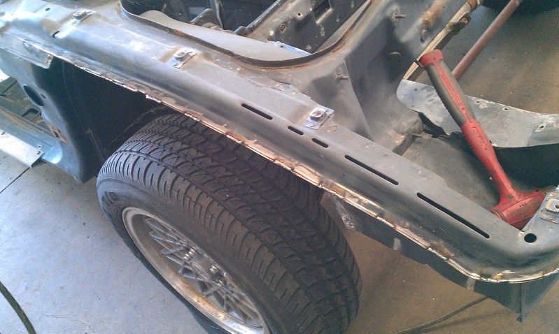
I have started the process, the effort is too much to make it worthwhile, the coating is deep inside the seams and reqiures a lot of work to remove manually. Chemical stripping would work best. Wire feed welding just does not like the contamination from the coating.
Most of the stiffness is lost in the overall design of the frame rails, they are not stiff torsionaly stiff on there own. Also, they don't tie in wtih the cab structure well. The cab's tunnel has areas that could use some platting and reinforcing as well to increase the connectivity from front to rear. It seams the fiero was designed with a target bending stiffness and harmonic response, and the engineers did there best to meet that, instead of creating a very stiff chassis.
IP: Logged
01:50 PM
Nov 9th, 2012
Will Member
Posts: 14303 From: Where you least expect me Registered: Jun 2000
There are specific areas I have seen that can really benifit from some stitch welding, Where frame rails mate to bulkheads, the forward cradle mounts, and the front suspension mounts.
I have started the process, the effort is too much to make it worthwhile, the coating is deep inside the seams and reqiures a lot of work to remove manually. Chemical stripping would work best. Wire feed welding just does not like the contamination from the coating.
Most of the stiffness is lost in the overall design of the frame rails, they are not stiff torsionaly stiff on there own. Also, they don't tie in wtih the cab structure well. The cab's tunnel has areas that could use some platting and reinforcing as well to increase the connectivity from front to rear. It seams the fiero was designed with a target bending stiffness and harmonic response, and the engineers did there best to meet that, instead of creating a very stiff chassis.
To effectively stitch a chassis, it really needs to be dip-stripped to bare metal everywhere. This is neither easy nor cheap. Once the seams have been stitched, it then needs to be e-coated to cover up the bare metal.
Compard to many of its contemporaries, especially in the same weight class, the Fiero is quite stiff and strong... just not so much by modern standards.
GM should have kept the overall length the same, but moved the front axle forward enough to get the wheel houses out of the footwells. That would let them make the footwells square and straight instead of tapered and canted. THAT would let them widen the front end of the tunnel significantly and make the car a true backbone chassis. As-is, it's somewhere between a backbone and a perimeter frame, but does neither very well.
Anyone who's had to climb over the door sill in a C4 Corvette knows what a nuisance the perimeter frame can be. The Lotus Elise is designed as a perimeter frame and I can barely get into it at all. Fortunately the Fiero doesn't really have perimeter frame... but it should have had something a bit more than it has. The overhead structure is exceptional, though and makes a strong contribution to the chassis' stiffness. That's why making a targa Fiero requires soooo much bracing to keep the rest of the body stiff once the roof is removed.
IP: Logged
09:53 AM
Will Member
Posts: 14303 From: Where you least expect me Registered: Jun 2000
How critical are the upper front rails, really, to torsional stiffness? I would think that most of the suspension loads go through the lower rails and the upper ones are only there as crash structures and to support the fenders.
That's another rub of trying to stitch a chassis... Without essentially leving it on a fixture for measuring torsional stiffness and measuring said stiffness EVERY time you stitch a seam to see how much that seam really contributed to the body's stiffness, you really don't know if your work has any effect at all.
[This message has been edited by Will (edited 11-09-2012).]
I don’t think the front upper frame rails are that critical to torsional stiffness, at least in the factory connection methods. At the rear they contribute to the roll resistance a fair amount though, as the strut top loads are transmitted through the upper more than the lower rails. Cornering loads are shared with the cab rear bulkhead "tube" and the lower frame rails, the lower frame rails have almost no triangulation laterally, making them weak in cornering. If the cradle has soft mounting, the frame can displace relatively easily (parallelogram). I would add some triangulation to the lower frame rail to the rear bulkhead tube. (The only real contribution of linking the upper and lower rails is the strut towers) I would also do more the stabilize the forward cradle mounts to the perimeter rocker panels, as well as increase the width of the rockers. GT skirts have ample room to just about double the width. The cradle is held latterly by only thin strips of metal at the front. The center tunnel has two formed beams that run along the top edge, then end at the rear firewall. This is the same height as the tube along the lower rear. That tube is incomplete in the center due to the fuel tank. The center tunnel beams flare out and end without contacting the firewall. The sectional area of the center tunnel at this point if very low, it cannot resist much torsion due to this. This would be ok, the rear of the cab has giant structures on each side for the rollover bar, and hold in the upper frame rails, however the only connection between the sides and the tunnel is the floor, the connection could be sounder, by connecting the center tunnel, rear bulkhead tube and the cradle mounts. On both of my cars the spot welds were over stressed at the cradle mount, and the sheet metal had began to delaminate.
The front upper frame rails feed in to the windshield pillars and the front bulkhead “tube” is morphed into the floor. The lower frame rails diverge into the cab floor, and connect to the upper frame rails at the front bumper; this connection is with thin sheet. The two lower frame rails take most of the cornering load. While the forward foot wall structure shares some corner load, and takes almost all bump loads due to the lower control arm mount. These tabs could use some better joining. The lateral Triangulation is ok, but has room for improvement, since the upper rails are not tightly connected to the lowers; the inner fenders are very thin sheet metal. Linking the upper and lower rails here is a good way of stiffening the front, in bending and torsion (ideally right by the cross member and triagulation to the firewall). I only started with the upper frame rails, because they were the easiest seam to start with. The plan was to start the stitching from front to rear, from the top down. It started as top side front, the sides on the front, the underside of the front, top of cab, inside cab, bottom of cab. Top of rear, inside rear, to the bottom of the rear. Mild steel wire is cheap, I’m not interested in any before or after, simply because before is a non factor. My only goal is to have the total tensional resistance a factor greater the roll resistance spilt F/R Also, I do not recommend fully welding seams. That will cause excessive warping of the thin sheet the frame is made from. The benefits of fully welded seam are not that much higher than the seam welded on 1" or 2" intervals. The area moment of inertias for the most stressed parts of the frame are the biggest factors in resisting loads, either in bending or torsion. As long as the joints are more than rigid enough to resist rotation, the stiffness of the members will be the limiting factor.
IP: Logged
10:58 AM
Will Member
Posts: 14303 From: Where you least expect me Registered: Jun 2000
Figuring out amd measuring which joints make the biggest contribution to stiffness would be an interesting projec, but the results would only be worthwhile to a very small audience.
IP: Logged
11:28 AM
fieroguru Member
Posts: 12603 From: Champaign, IL Registered: Aug 2003
For the front end, I wouldn't mess with stitch welding, just add a cross brace from the front lower frame rail right above the front crossmember attachment to the base of the opposite side A-pillar area and do both sides. Some 1" tube and a moderate amount of plating/welding and you would be done for the front.
For the front end, I wouldn't mess with stitch welding, just add a cross brace from the front lower frame rail right above the front crossmember attachment to the base of the opposite side A-pillar area and do both sides. Some 1" tube and a moderate amount of plating/welding and you would be done for the front.
A full 8 point road race roll cage can accomplish a large part of this by connecting the front lower frame rails to the door bars, with appropriate plating.