Coming off the sending unit, one is green and the other is green with a white tracer. You can insert a paper clip into the lead and ground each one to find which is for the light and which is for the gauge.
IP: Logged
04:36 PM
ericjon262 Member
Posts: 3158 From: everywhere. Registered: Jan 2010
I'm just trying to match the colors on my wiring harness I'm building for my 3500 swap, do you know which is supposed to be the light and which is supposed to be the gauge? I don't care about the light, but I do want the gauge to work, and my CTS only has 2 outputs, one for the ecm, and one for the gauge.
------------------ there's a Group on 60degreeV6.com for us 660 Fiero owners!
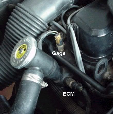
The coolant temp sensor doesn't control the gauge on a 2.8. Its signal is used by the ECM to control the injectors.
The schematic says the two wires for temperature are light green and dark green but with visual inspection of my 3 cars, the wires are the same color green with one being solid and the other with a white or yellow tracer.
The solid color wire is the temp light and the wire with the tracer is for the gauge. This is coming from the corner of the V6 head nearest the coil.
IP: Logged
06:16 PM
ericjon262 Member
Posts: 3158 From: everywhere. Registered: Jan 2010
What i would like to know is what side of the sensor is for the light & what side is for the gauge? I'm working on a swap and don't have the original wire colors. I used a connector from off the coil of a GM truck - it has the same connector as the 2 wire temp sensor.
IP: Logged
07:20 PM
fierofool Member
Posts: 12993 From: Auburn, Georgia USA Registered: Jan 2002
Bixby, the solid green wire (light) goes to the terminal nearest the slit in the side of the sender. That's for the light. The wire with the tracer (gauge) is the other.
So if I hold the sensor so that the tab that hooks the the wiring harness is at the bottom of the mushroom shape, the left wire is what color? Thanks.
quote
Originally posted by fierofool:
Bixby, the solid green wire (light) goes to the terminal nearest the slit in the side of the sender. That's for the light. The wire with the tracer (gauge) is the other.
IP: Logged
06:46 AM
hookdonspeed Member
Posts: 7980 From: baltimore, md Registered: May 2008
Bixby, I thought you were using the original 2.8 gauge sending unit. I was describing that sender. The wiring for that sender are as I described for the gauge and light. Sorry.
IP: Logged
09:37 AM
ericjon262 Member
Posts: 3158 From: everywhere. Registered: Jan 2010
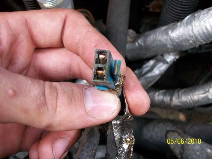
Could some one take a picture of their pigtail for this two wire connector for me? One that shows the wires as well as the connector? Stupid request but it sure would help me.
Thanks. I guess it's the v6 one I'm in need of more, the sensor on the left top picture . I'd like to see the clip on the plug & the colors of the wires going to the plug as well.
IP: Logged
06:25 AM
phonedawgz Member
Posts: 17106 From: Green Bay, WI USA Registered: Dec 2009
The sensor on the top left, the two wire CTS - connects to the ECM only and has no provisions for gauge.
How most people solve this problem, is they swap the 2 wire CTS for a 3 wire combo CTS and temp gauge sender.
With the 2 wire CTS, you had a yellow and a black wire. The yellow wire ran to the CTS input of the PCM. The black wire ran to the ground (return) connection for the CTS.
When you swap to a 3 wire CTS, it will have a black wire, a yellow wire, and a green wire
The yellow and black wires run as they did with the 2 wire CTS. The green wire then connects to the temperature gauge.
Usually there is an output on the PCM to control the temp light. My suggestion is to hook that up also, just so you have an alerting visual indication if the engine does start to overheat.
PM or email me if you need a 3 wire pigtail and I can supply you with one.
[This message has been edited by phonedawgz (edited 09-02-2012).]