With all due respect to olejoedad, if you do the math correctly you can setup the tie rod to be attached to either the control arm or cradle and have the angle correct so that its angle matches the angle of the knuckle to control arm thus removing any “toe change”. However the trouble is probably not worth the effort unless you’re one of those who enjoy doing it just for the fun of figuring it out (I’m in that camp). DANH, nice effort. I wish I had the time to take a stab at it. Enjoy and drive safe.
IP: Logged
01:32 PM
Apr 12th, 2012
zkhennings Member
Posts: 1931 From: Massachusetts, USA Registered: Oct 2010
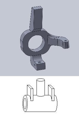
Don't sell anything! Sorry for how rediculously awful this is of a drawing but this is what I have been thinking about doing
Not only does it fix bumpsteer but improves roll center if car is kept at stock height and if car is lowered it would preserve the stock geometry with still some improvement over stock.
I see what you are doing just one question how is it not going to rotate on the ball joint. I see you have it tied to the tie rod mounting point but what is to stop the the block that you added from rotating .
IP: Logged
08:36 AM
zkhennings Member
Posts: 1931 From: Massachusetts, USA Registered: Oct 2010
Same way that the knuckle doesnt rotate on the ball joint now. I think you are missing the part where there is still a tierod, it is just attached way at the bottom of that cylinder below the original tie rod attachment point so it is at the same level as the balljoint. Ill do it up in solidworks later today and post back
Keep in mind that the forces that are on the knuckle are massive. The if your fix isn’t strong enough you’re liable to find out the hard way. If you look at the Westshore arm it’s very sturdy for a reason.
IP: Logged
10:29 PM
Apr 15th, 2012
Pyrthian Member
Posts: 29569 From: Detroit, MI Registered: Jul 2002
Originally posted by olejoedad: You all crack me up!
Do you really think that GM engineers did such a poor job on the rear suspension of the pre-88's that your homemade "fixes" will solve the "problem"?
Renew the worn suspension parts and learn to drive!
And the sway bar causing your bumpsteer?
well - to start with - they did NOT even make a rear suspension.... that was 30 years ago. and, if you go by the age of the Citation FRONT suspension used - 35 years?
but - yes - most bumpsteer whining is due to sloppy old bushing & worn struts. and - yes - a sway bar will cut down on bumpsteer
IP: Logged
11:53 AM
zkhennings Member
Posts: 1931 From: Massachusetts, USA Registered: Oct 2010
If need be instead of flat steel on the bottom It could be steel bar. But I really do think it would be strong enough. Here let me cad it give me like half an hour
IP: Logged
03:14 PM
zkhennings Member
Posts: 1931 From: Massachusetts, USA Registered: Oct 2010
asuming larger wheels, i like that fix. the question would be where are you to mount he inner joint of the tie rod end? it has to be in the same plane as the control arm, and the same length.
if you mount it to the cradle or the control arm you still have to deal with bushing movement (which i believe to be the original cause of the bumpsteer concerns). if the tie rod is attached to the control arm, then the bushings will cause the whole arm will twist back under load and effectively steer the wheels still. (even though the knuckle does not change toe in relation to the arm, the whole thing moves). if you attach the rod end to the cradle (more like a steering rack would be) you will have some movement of the arm in and out under cornering forces, and will still cause steering (knuckle will change toe in relation to the arm). i think the cradle mount will create less movement though.
or just create an upper arm and be done with it!!!
Uh… sorry but you have to be able to adjust the toe and the knuckle needs to be able to pivot. The drawings look like the knuckle is fixed to the control arm. The HT motorsports control arm still provides for toe adjustment and for the camber angle to change with suspension movement.
I understand not wanting to spend the money but have you thought about building your own version (cope their design)?
IP: Logged
12:08 AM
PFF
System Bot
Khw Member
Posts: 11139 From: South Weber, UT. U.S.A. Registered: Jun 2008
I would think the best way to do it would be to change the lower ball joint design so it's no longer a ball joint. I have a idea in my head, but it'd take time to draw something up and even then there may not be enough room on the actual a-arm to implement the idea.
Edit: Something like this with a poly bushing and a mod to the lower a-arm with a shaft for it to mount to in a swivel base to allow for adjustment.
I would think with that kind of a set up you could remove the tie rod link completely and totally eliminate the bumpsteer. Problem is like I said, I don't know if there is enough material to work with on the lower a-arm to do it.
[This message has been edited by Khw (edited 04-16-2012).]
IP: Logged
12:34 AM
zkhennings Member
Posts: 1931 From: Massachusetts, USA Registered: Oct 2010
no you still use a ball joint it still pivots on the control arm and I would mount the tierod end to the control arm like in the HELD system.
But yea it may require bigger wheels depending on the offset.
And the only reason I would go with this instead of fabricating control arms like the HELD system has is because fabricating control arms is really hard and you have to make jigs for it as well to make sure both sides are identical.
I also considered this but instead of having that thick piece at the bottom which moves where the ball joint attaches just having a supporting piece bolted to the bolt that holds the ball joint in the knuckle and it would support the cylinder that drops the position of where the tie rod attaches to the knuckle... Ill post pics soon. I worry about strength tho
IP: Logged
02:10 AM
zkhennings Member
Posts: 1931 From: Massachusetts, USA Registered: Oct 2010
If I understand it right, your idea should work but you would lose toe adjustment.
I have yet to see a disassembled rear suspension in person, but what I gather from the GM service manual and the images on auto part sites, the ball joint slides into the knuckle and is held in place by a bolt. The only question I'd have is how the bottom of the knuckle would hold up to the stresses imposed that would otherwise be taken care of by the toe links.
IP: Logged
02:26 AM
zkhennings Member
Posts: 1931 From: Massachusetts, USA Registered: Oct 2010
View from BOTTOM you can see how the support for the cylinder is hollow
All of these use stock control arm and ball joint! As you can see there might be slight clearance issues with the control arm but a grinder could fix that there is defintely extra material shown here. This would not change the suspension geometry and I think it would be really strong. Tie rod now attaches to knuckle at bottom of cylinder.
Also I did not post a picture depicting this but the main bolt holding this onto the knuckle is the bolt that holds the ball joint in the knuckle I will make an assembly tomorrow with control arm and tierod
[This message has been edited by zkhennings (edited 04-16-2012).]
IP: Logged
02:50 AM
Doober Member
Posts: 445 From: Oro Valley, AZ/Swartz Creek, MI USA Registered: Nov 2006
Ok... so how do you keep it from rotating and steering the rear of the car? I don't see a way of keeping toe in check. What you've drawn would certainly help with strength though.
IP: Logged
02:59 AM
engine man Member
Posts: 5316 From: Morriston FL Registered: Mar 2006
the way to get rid of bump steer is to make the tie rod the same exact length as the lower control arm pivot points so both the tie rod and lower control arm have the same length from pivot point to pivot point then you must get the tie rod at the same angle as the lower control arm so the travel the same arc so no bump steer will happen just find your self a good racing chasis book and they will show you exactly what i am talking about it not realy hard to do just takes time shimming the outer tie rod end up or down . BTW the stock tie rod is about 2 inches to long the inner mounting point needs to be moved out 2 inches for each wheel
IP: Logged
02:23 PM
olejoedad Member
Posts: 19892 From: Clarendon Twp., MI Registered: May 2004
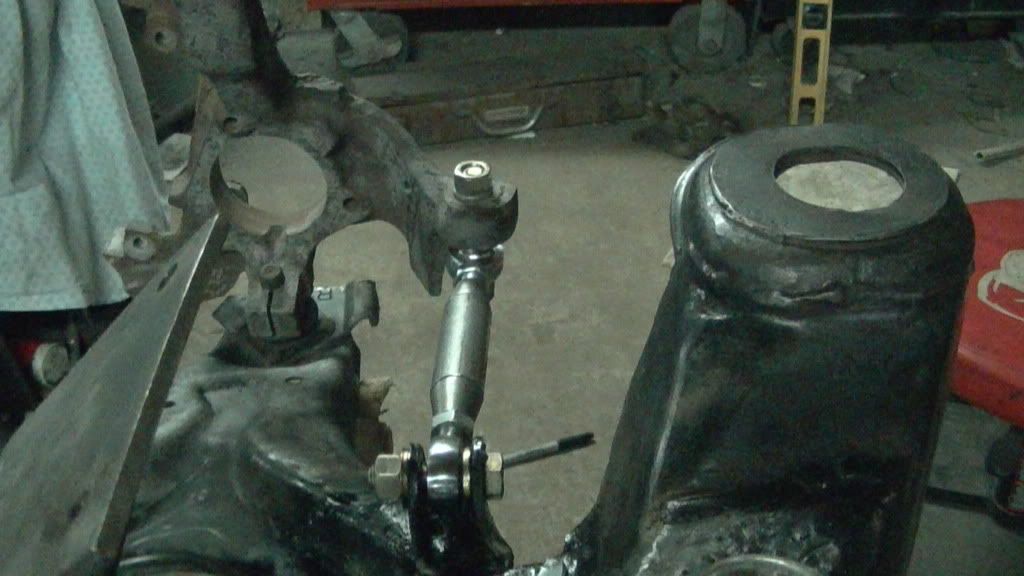
Has anyone considered retrofitting an '88 Fiero rear knuckle? The A-arm could be replaced with a pair of rods, like the custom toe link pictured above. Make one of the rods adjustable for length, and toss in a trailing arm, and you basically have the '88 rear suspension.
IP: Logged
05:09 PM
zkhennings Member
Posts: 1931 From: Massachusetts, USA Registered: Oct 2010
I have thought about it and then you could run the vented 88 brakes as well which would be nice but do the struts from 84-87 bolt up?
And in both my designs, there is a ball joint, and then there is also a toe link which attaches at the bottom of the cylinder. The other end could be attached to the control arm or right beside the control arm on the cradle. Cut out a small square in the cradle and lengthen the bolt that goes thru the bushing and attach the tie rod end at the same rotational point as the control arm.
This would be a cradle swap and to complete this, you'd have to do a few things according to this thread:
1. Modify to the strut mounting points yourself or just buy the kit from Held/Araut Motorsports for $75 (funny how their name keeps coming up in this thread. LOL!).
2. Make or buy a rear coilover setup.
3. Modify one of the motor mounts
4. Change to the shorter 88 cradle bolts
5. Modify front brakes as the change to the '88 rears creates an imbalance (Grand Am front brake upgrade w/ stock '88's supposedly suffice).
6. Add/modify exhaust spring mounts.
Unless you're just in it for shits and giggles (wanting to just take on the challenge for the sake of taking on the challenge), this would, by far, be the easiest/cheapest route...IMHO and is the route I am planning on going for the '87 I bought (as it came w/ the coilovers already installed and I have a fiero parts hoarder in the area that has several rust free '88 cradles for a very reasonable price).
[This message has been edited by akademikjeanius (edited 04-16-2012).]
IP: Logged
08:30 PM
Doober Member
Posts: 445 From: Oro Valley, AZ/Swartz Creek, MI USA Registered: Nov 2006
I have thought about it and then you could run the vented 88 brakes as well which would be nice but do the struts from 84-87 bolt up?
And in both my designs, there is a ball joint, and then there is also a toe link which attaches at the bottom of the cylinder. The other end could be attached to the control arm or right beside the control arm on the cradle. Cut out a small square in the cradle and lengthen the bolt that goes thru the bushing and attach the tie rod end at the same rotational point as the control arm.
The arm to the bracket you designed would have to rotate on the same axis, and The arm needs to be of the same rotational distance from that axis (basically it still would need toe adjustability). It couldn't be attached as you are saying for the same reason as the previous welded bracket... you would induce toe in/out conditions every time the suspension articulated.
[This message has been edited by Doober (edited 04-16-2012).]
IP: Logged
10:01 PM
zkhennings Member
Posts: 1931 From: Massachusetts, USA Registered: Oct 2010
=) Don't worry you must just be misunderstanding my design but I will make some models soon like I promised!
And I would rather not do the whole cradle swap I figure if need be I could use 88 struts and get the kit for 88 struts in a 84-87.
I will probably go that route eventually but for right now I'm going to try this fix out. I am really considering making my car into a full on race car in which case I might not be allowed to change pickup points on the suspension which means the bumpsteer fix is ok but changing over to 88 knuckles and stuff would not be unless I did a whole cradle swap In which case I might as well just sell my car and buy an 88. Which I dont want to do! I love my car.
IP: Logged
10:22 PM
olejoedad Member
Posts: 19892 From: Clarendon Twp., MI Registered: May 2004
I don't misunderstand it, you're just moving the attachment point of the toe link arm down. This still won't work if you attach it to the a-arm itself. If you attach this cylinder you've designed to the same shaft as the control arm you will still run into toe issues. If you use a shorter or longer arm, the toe changes as the suspension articulated. I'm also changing my argument I made earlier about the same rotational point, the arm connected to this point still needs to be the same distance as the distance between th control arm pivot and the ball joint.
Your bracket could still be used, but you would need a pivot mounted to the cradle, and the link going to the bracket will need to be the same angle as the control arm at rest for peak effectiveness, at least in an ideal world where the tires stay perfectly perpendicular to the road.
[This message has been edited by Doober (edited 04-16-2012).]
IP: Logged
10:41 PM
Apr 17th, 2012
zkhennings Member
Posts: 1931 From: Massachusetts, USA Registered: Oct 2010
Here you go, an assembly showing how you can have an adjustable toe link attached right to the control arm and still get zero bumpsteer always with the fix I made. All that matters is that the attachment point of the toe link to the knuckle is on the same parallel axis to the control arm axis as the ball joint. You will see, so I made the assembly, put it in a front view, and then moved the suspension up and down and took screen shots to show you how it doesnt change at all.
and here they are of the suspension being moved
[This message has been edited by zkhennings (edited 04-17-2012).]
IP: Logged
03:02 AM
zkhennings Member
Posts: 1931 From: Massachusetts, USA Registered: Oct 2010
OK now I see what you were saying to me, in my mind I knew I was going to move the position where it attached to be on the same axis as ball joint as well as same height But I guess I never stated that and in my model I did not move the point yet. I was just trying to create a surface upon which the toe link attachment would be at the right height and then could just be placed anywhere on the axis. Sorry if I was being frustrating!
IP: Logged
03:09 AM
zkhennings Member
Posts: 1931 From: Massachusetts, USA Registered: Oct 2010
And I am not saying I would attach it to the control arm but I am just saying it can work if everything is lined up correctly. So to the OP, here is what you would have to do to use your modified control arms and tierods and the reason I told you not to get rid of them!
The pivot point of the tie rod (inner side) needs to be at the same location as the pivot point of the control arm and needs to be parallel to the control arm throughout the entire travel. (You're getting close)
I beg to differ. When I put my first setup on here And was show what was wrong I went back to the scene of the crime and changed things up. I moved the Hiem joint down and in line with the ball joint pivot axes and moved the back anchor point that was on top of the control arm to the side. Then I did the test to see if the knuckle would move. After a few adjustments. I could move the assemble up and down and the knuckle would not turn. I think the reason that this works is the rear attachment point moves up and down with the control arm and the other joint moves along with the ball joint. no movement. But it does take time to get it aliened but It does work.
IP: Logged
12:16 PM
PFF
System Bot
Doober Member
Posts: 445 From: Oro Valley, AZ/Swartz Creek, MI USA Registered: Nov 2006
The pivot point of the tie rod (inner side) needs to be at the same location as the pivot point of the control arm and needs to be parallel to the control arm throughout the entire travel. (You're getting close)
I will concur with this if you mean the link needs to be the same length of the arm and needs to stay parallel to the arm (in essence what I was trying to say earlier)
That's why the mount for the link is so high, because of the location on the casting.
[This message has been edited by Doober (edited 04-17-2012).]
Well mine is about 3/4 the leaght of the control arm. My mount for the control artm is about 4 inch from the bushing. And it still works fine .Like I mentioned it moves with the arm and the hiem on the ball joint side pivots on the ball joint axis center line. not at the center of the ball joint but at the bottom of the joint.center of the ball.
IP: Logged
01:43 PM
Doober Member
Posts: 445 From: Oro Valley, AZ/Swartz Creek, MI USA Registered: Nov 2006
I did put a dial indactor on the contol arm and measured the sida to side movement of the hub. .010 from hub a ride Height to full compression to full relax.
The problem you will find is that when you put it on the car and adjust the toe and camber I’ll lay money on it that you will get rotation when you raise and lower the assembly. It is simple mathematics. What you’ve probably done is found the “sweet spot” where the tie rod moves in the same arc that the control arm does however what you need to be able to do is adjust the toe and camber to any angle and still have the arc’s track each other when the knuckle moves up and down. The only way to do that is to have both the tie rod and control arm parallel to each other. Or, do what HT did and have the control arm limited to camber only (no rotation).
IP: Logged
02:21 PM
zkhennings Member
Posts: 1931 From: Massachusetts, USA Registered: Oct 2010
Haha trust me I know where everything needs to be located its simple kinematics I am sorry if I am not articulating myself well but as you can see the center of the ball joint and the center of the heim joint on the toe link are perfectly lined up along the axis parallel to the axis that runs between the two control arm bushings ( I hope that's clear now and yes I know that if it wasnt mounted to the control arm, the toe linke would have to literally be in the same plane as the control arm if it was mounted to the cradle which impluies that it would also be parallel). And as you can also see, there is zero toe movement as the suspension moves so I really do know what I am doing if you are still not convinced. I just worry about minimizing unsprung weight but I dont think it would be terrible.
And DANH you really need it to be lined up this way in order to 100% eliminate the bumpsteer. Like I said, yours would help but not fix it completely. You got the toe link connection closer to the axis that the ball joint lays on that is parallel to the control arm bushings axis, but it needs to be right there and I dont think you could make a strong enough setup to accomplish this with out a bracket with at least two attachment points to the knuckle. I also thought about bolting something to the otherside of where the hub bolts to but I think it would definately have issues with not getting in the way of the axle.
If you can modify your setup just move the Hiem joint inbetween the origin tie rod mount and the ball joint on at the same height you have it and the same mounting point on the control arm. See if you have any movement All I did was take your set up and instead of mounting the Hiem were you have it I moved it in so the tie rod would be parallto the control arm. same setup and brakets just moed the onme side in to the basll joint.
IP: Logged
03:23 PM
zkhennings Member
Posts: 1931 From: Massachusetts, USA Registered: Oct 2010
I dont think the HT control arm is limited to camber only..... Im pretty positive that gold link is to adjust the Toe... In my design you can still adjust the toe... When I get home I will shorten the toe link and take more screen shots to show that the toe remains the same thru the suspension travel
IP: Logged
03:24 PM
Doober Member
Posts: 445 From: Oro Valley, AZ/Swartz Creek, MI USA Registered: Nov 2006
The design of their arm is vaguely similar to how I would probably design one: solid-mount the ball joint location to the tie rod end for bracing, then find optimum toe (unless it's simply 0) and build a lower arm with that toe built in. A downside is the added unsprung weight.
[This message has been edited by Doober (edited 04-17-2012).]