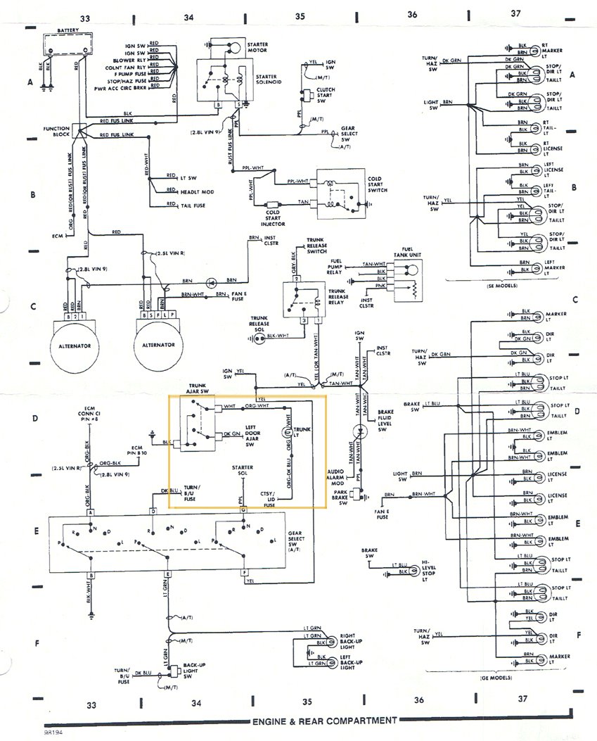
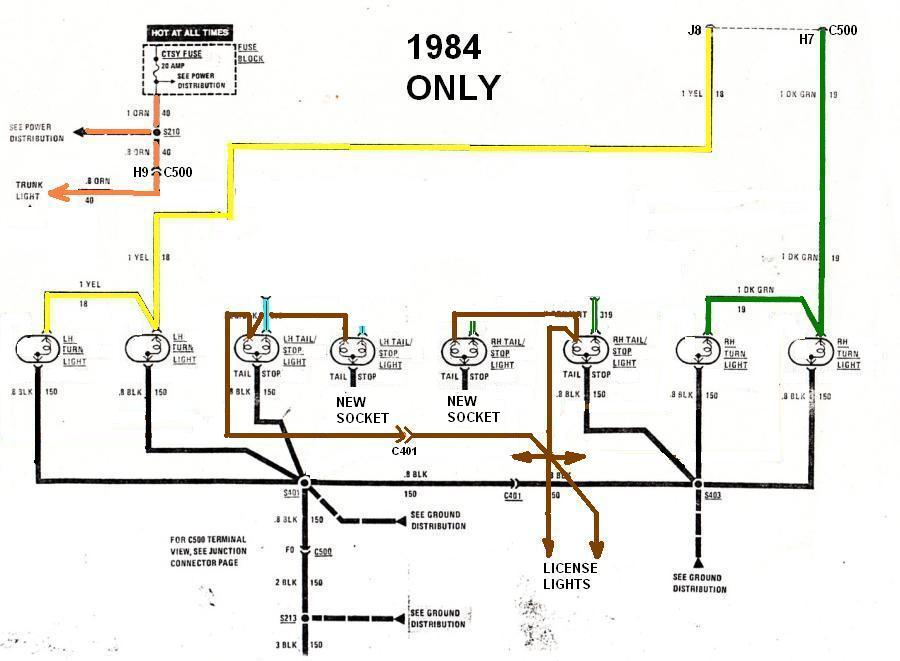
OK, as promised, here's the stock tail light wiring harness schematic (less the reverse lights):
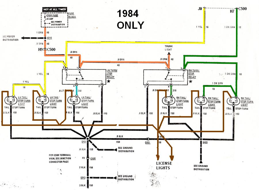
Step 1. Remove the two relays that are near the LH decklid hinge box (see below). Note that I've erased the two black ground wires for the relays since they're not needed anymore, and I've rerouted the trunk and RH turn signal wires a bit for clarity:
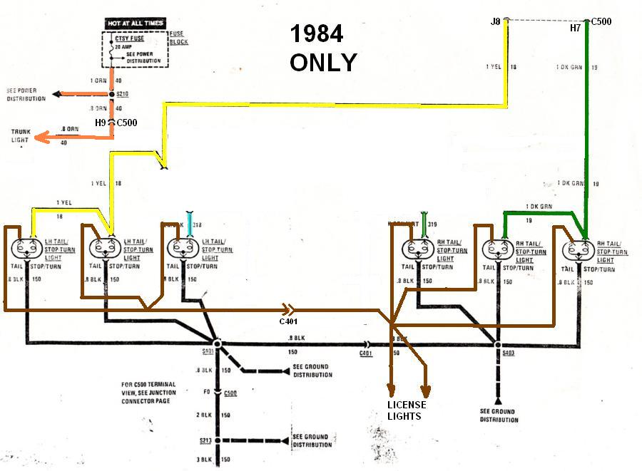
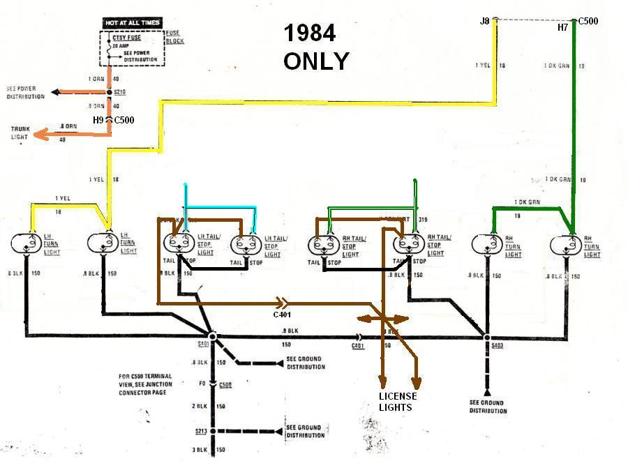
Step 2. Clip and tape up the brown wires leading to the four future turn-signal-only bulbs, near to the sockets. These are the sockets with the dark green wires on the RH side and yellow wires on the LH side. Once clipped, the low intensity filament for these four sockets won't work anymore, and these sockets are ready to be used for the four turn signal bulbs (two bulbs per lens, one lens per side). If you have OEM Ferrari tail lights with integral bulbs, then cut off the fiero sockets and splice the yellow and black wires to the Ferrari pigtails for the LH side and the green and black wires to the RH side. Also at this point, you can attach the reverse lights to the center bulb location in the turn lens. The reverse lights have light green wires (not shown);
For the stop/marker lights: If you've got the OEM Ferrari lenses then go to Step 3a, if not, then go to Step 3b.
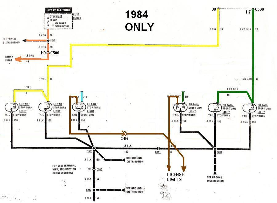
Step 3a. Clip off the light blue wire with the black stripe, the black wire, and the brown wire from the remaining LH socket and splice those wires to the brake, ground, and low marker bulbs respectively on the Ferrari LH side lens. Do the same on the right hand side except that the brake light gets spliced to the green wire with black stripe. Skip to Step 4.
Step 3b. If you don't have the OEM Ferrari lenses with integral sockets, and you're planning on using the Fiero sockets, then you'll need two extra dual filament bulbs and sockets to complete the circuit. I've drawn them in the schematic below already. Use a jumper wire to connect the brown wire from each of the old sockets to the low intensity (marker) bulbs on the new sockets:
Step 3c. Next splice the black ground wires from your old sockets, and the blue/black, and green/white wires to the appropriate wires on your new dual filament sockets like so:
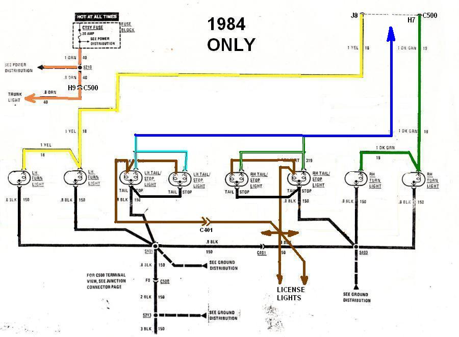
Step 4. Go to where you unplugged the two relays in step 1, snip off the blue/black, and green/white wires fron the relay connectors, and splice both wires together along with a new wire leading to C500 like the dark blue wire below:
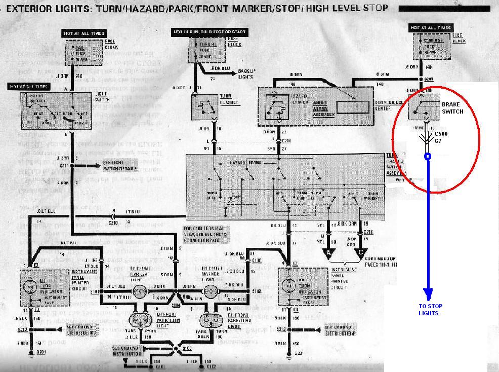
Step 5a. Here's the only part I'm not entirely certain about regarding the '84 circuit. This is what the stock lighting circuit looks like on the inside of the passenger compartment for later years and most likely the same as the '84. It's busy, but the only part you have to concern yourself with is the part circled in red. The power from the brake light switch goes from the switch to C500 pin G7 on the chassis side of the connector. Then, on the engine side of the connector, G7 just loops back to pin H8, again on the engine side of the connector. From there, H8 goes back into the pasenger cabin to the Turn Hazard Switch assembly. Examine your C500 connector closely to be sure it's in the same configuration. If it isn't, then jump to step 5c. If it is like this, then simply cut the loop on the engine side of the connector between C500 pins G7 and H8... leaving as much wire as possible on the side with G7 like this:
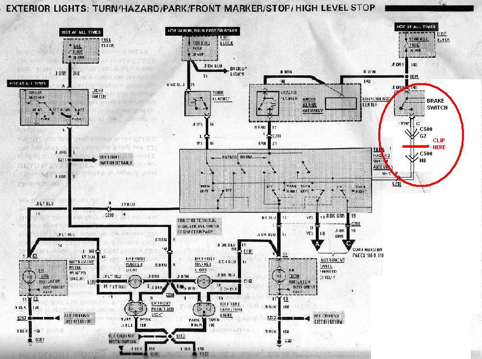
Step 5b. Splice the new wire (dark blue) from step 4 above, to the white wire leading from C500 pin G7. Jump to Step 6.
Step 5c. If you stopped here it's because you don't have a white wire jumping from C500 pins G7 to H8. In this case, you must find the connector at the brake switch and cut the white wire leaving as much wire as possible on the switch connector. Then, splice a new wire to the end of the white wire (the end still attached to the switch connector) that is long enough to reach the new (dark blue) wire you added in step 4 above, and splice these two ends together as well.
Step 6. Sit back and enjoy your new tail lights.