I have been building 3800 swap harnesses. I would like to bounce around what is the best way to test these harnesses before shipping them to the purchaser.
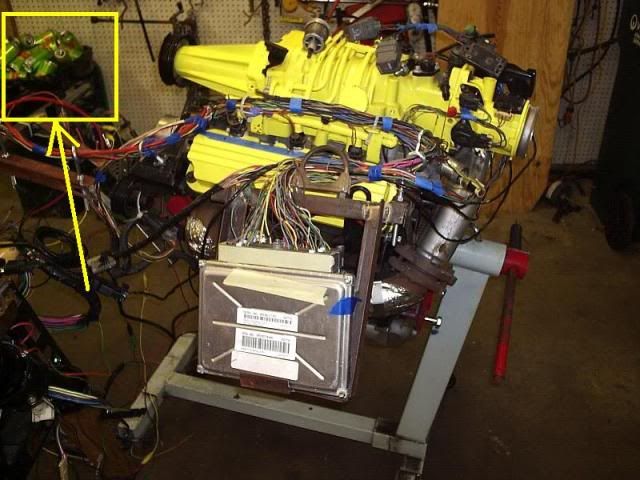
My build/test rig
I can with the scanner see the TPS, CTS, IAT, MAP, HO2, VSS
The scanner will tell me an error if the EGR, or EVAP purge or EVAP vent systems are not present.
I have indicator lights in the dash to indicate REV Switch, Fuel Pump,
I can read the oil pressure sender and temp sender from gauges on the dash
After turning the key off I can see the IAC pintle reset. I can also watch the amperage on the power supply and verify the HO2 is heating.
I can crank the engine and tell that the fuel pump relay is activated again, and I can watch the noid lights on the injectors fire. I can also see the spark for each coil pack (Test wire to a gap to the other terminal.
For complexity reasons I do not want to actually fire up the engine itself. It's easier to work on the engine on just the stand. Exhaust and cooling systems would get in the way. I can use this wiring/test rig for 3800 NA also but would not be able to run it with my SC engine. Actually running the engine would provide no additional electrical information the way I see it.
So other than actually running the engine, is there any other checks or changes that you can think I should make? --- http://reddevilriver.com
[This message has been edited by phonedawgz (edited 09-30-2011).]
IP: Logged
02:38 PM
PFF
System Bot
Gall757 Member
Posts: 10938 From: Holland, MI Registered: Jun 2010
I'm not familiar enough with the 3800 but some ECM's have inputs for AC to bump up the idle speed, and some control the radiator fan too. Does your harness have these provisions? Or even need them?
IP: Logged
04:49 PM
phonedawgz Member
Posts: 17106 From: Green Bay, WI USA Registered: Dec 2009
re cans of Sundrop - The cost of a harness barely covers the parts plus the cost of the Sundrop
re AC - Yes if AC is included then there is an AC input to the PCM, an AC relay, the AC clutch, and a separate AC pressure sensor. There may also be a switch on the ground side of the AC clutch.
All would be pretty hard to test. I'm quite careful in assembling the harnesses and after the PCM is pinned, I re-check the pinning. It would be hard to have a test set up to see the PCM turn on the AC relay. There are a few connections like that where the only tests I can do is to double check the wiring to be going to the right pins but can't really do a functional test.
So far things have been going good. The only problem I have found was a VSS connector with a mashed pin inside it. I didn't notice it wiring it, but the pin didn't always make connection when spinning the VSS with a drill. Looking into it showed the problem right away.
Radiator fan output is to an indicator bulb in the dash. ---
Side note - The PCM's are quite smart btw. They sense if there is a load on the output or not. When first testing the fuel pump relay output it would stay on all the time. That was because I was testing it with a logic probe. The PCM saw no load and just kept the output high. Putting a load on the output made the PCM give it the correct functionality. With no load on the low speed fan output the PCM gives an malfunction indication. Same thing for the high speed fan output btw. I don't use it so it shows up on my error on the scanner. My test PCM is not re-flashed yet.
The same errors show up for a missing EGR and both EVAP solenoids
[This message has been edited by phonedawgz (edited 05-14-2011).]
I have nothing of any value to add related to building/testing a harness but I think you need a can crusher!
"Sun Drop" = Fiero Wizard Fuel!
My recycler pays the same crushed or non-crushed. Yeah I go through a few more bags but it's well worth the time to crush them AND the nasty wasp attracting mess a can crusher makes. So I took mine off the wall and tossed it.
IP: Logged
05:37 PM
phonedawgz Member
Posts: 17106 From: Green Bay, WI USA Registered: Dec 2009
On the bad VSS connector the pin had split and part of the pin was pushed back and crinkled up. So if you would have tested the end to end the wire for continuity, the connector would have passed. But plugging the connector into an actual manual transmission VSS and spinning it with a drill is how I tested it. The speed showed up at first and then dropped off. I found wiggling the connector made it come and go. That's when I gave the connector a closer inspection and noticed the bent back 1/2 of the pin. So bottom line is I think using a live scanner feed is much better than using an ohm meter.
Dynoscan gives me a number output for the sensor. It also gives me a real time bar graph. I can also have the sensor data plotted over time. Dynoscan data over time can be saved and played back later. Dynoscan also has a 1/4 mile test feature. You take your laptop and plug it into your car. Then on a flat road you run a 1/4 acceleration. Based on gear ratios and tire size you program in it will give you a calculated 1/4 mile time. I wouldn't bet the farm on those times however I would think it's reasonable to use those times to judge performance vs a previous performance test on the same car.
Yeah I like it, but then I don't have much experience with other software to tell you how it stacks up against them.
Dynoscan is only ODBII. That means it doesn't work with an ALDL ODBI connector. I put ODBII connectors on all my 3800 conversion harnesses. That way I or any other mechanic can plug in a standard ODBII tester to scan the engine.
IP: Logged
05:42 PM
May 16th, 2011
fierogt27 Member
Posts: 836 From: Jacksonville, NC Registered: Jan 2011
You could do pin drag tests if you want. This is to test the pins grip to ensure it makes good contact with the pin it mates with. You only need to test the female pins, as they are the ones that can open up and become loose on the male pin. To test, just make some short pieces of wire with the desired male pin attached to one end, then slide that tester into the pins you want to check and feel how much force it takes to pull them apart. It's pretty simple, but there is no spec on how much force it should take. It's more of a "feel" type of thing. It takes very little force, as I'm sure you know. Basically, there just needs to be some drag. If the tester falls out, then the pin is too loose. After checking a few, you'll get the feel for it.
IP: Logged
07:41 AM
phonedawgz Member
Posts: 17106 From: Green Bay, WI USA Registered: Dec 2009
Oh. I was thinking about the pcm pins, injector pins, speed sensor pins, ect. Basically, the 3800 related pins. Those in the pic look like old school pins, are they fiero pins?
IP: Logged
11:25 AM
phonedawgz Member
Posts: 17106 From: Green Bay, WI USA Registered: Dec 2009
Yeah that is the VSS type pin. One of the sides of the male (VSS connector, harness side) pin was pushed back into the connector and all bent up. Thus the VSS didn't work 100% when tested. Replacing the pin in the connector fixed the problem.