Pennock's Fiero Forum
  Technical Discussion & Questions - Archive
  Inside the F40

T H I S   I S   A N   A R C H I V E D   T O P I C
  

Email This Page to Someone! | Printable Version


Inside the F40 by 1fatcat
Started on: 01-10-2011 11:02 AM
Replies: 17
Last post by: 1fatcat on 07-28-2011 11:32 AM
1fatcat
Member
Posts: 1519
From: Zimmerman, Mn
Registered: Dec 2010


Feedback score: N/A
Leave feedback

Rate this member

Report this Post01-10-2011 11:02 AM Click Here to See the Profile for 1fatcatSend a Private Message to 1fatcatDirect Link to This Post
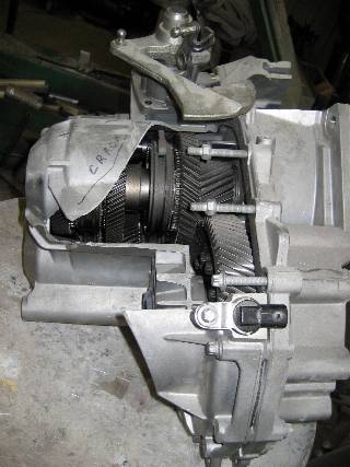
I have seen a number of times that people are wanting this info, so here it is!

THE ASSEMBLY


THE EXPLODED ASSEMBLY

1 - Case Bolt/Screw
2 - Bracket
3 - Vent Washer
4 - Vent Cap
5 - Transmission Case
6 - Shift Control Shaft Bushing
7 - Back Up Lamp Switch
8 - Shift Control Housing Bolt/Screw
9 - Shift Control - w/ Shift Control Shaft - Housing Assembly
10 - Oil Trough
11 - Input Shaft Bearing Shim
12 - Input Shaft Bearing Cup
13 - Input Shaft Assembly
14 - Input Shaft Bearing Cup
15 - Input Shaft Bearing Shim
16 - Shift Shaft Bushing
17 - 3rd, 4th and Reverse Fork Assembly
18 - Shift Shaft Bushing
19 - Upper Main Shaft Bearing Shim
20 - Upper Main Shaft Bearing Cup
21 - Upper Main Shaft Assembly
22 - Upper Main Shaft Bearing Cup
23 - Upper Main Shaft Bearing Shim
24 - Clutch Housing
25 - Central Release Bolt
26 - Clutch Master Cylinder Assembly
27 - Clutch Master Cylinder Screws
28 - Clutch Master Cylinder Seal
29 - Drive Axle Seal
30 - Case Bolt
31 - Magnet
32 - Lower Main Shaft Bearing Shim
33 - Lower Main Shaft Bearing Cup
34 - Lower Main Shaft Assembly
35 - Lower Main Shaft Bearing Cup
36 - Lower Main Shaft Bearing Shim
37 - Shift Shaft Bushing
38 - 1st, 2nd and 5th/6th Fork Assembly
39 - Shift Control Shaft Bushing
40 - Front Differential Bearing Shim
41 - Front Differential Bearing Cup
42 - Front Differential Assembly
43 - Front Differential Bearing Cup
44 - Front Differential Bearing Shim
45 - Vehicle Speed Sensor Bolt/Screw
46 - Vehicle Speed Sensor Assembly
47 - Vehicle Speed Sensor Seal
48 - Case Bolt/Screw
49 - Drive Axle Seal


THE SHIFT RAIL

400 - 5th and 6th Shift Fork Assembly
401 - Shift Fork Pads
402 - Shift Fork Pad
403 - 1st/2nd and 5th/6th Shift Shaft
404 - 1st and 2nd Shift Fork Assembly
405 - Shift Fork Pads
406 - Shift Fork Pad
407 - Shift Fork Pin
408 - Reverse Shift Fork Assembly
409 - Shift Fork Pads
410 - Shift Fork Pad
411 - 3rd/4th and Reverse Shift Shaft
412 - 3rd and 4th Shift Fork Assembly
413 - Shift Fork Pads
414 - Shift Fork Pad
415 - Shift Fork Pin


THE INPUT SHAFT

100 - Input Shaft Bearing Bolt/Screw
101 - Input Shaft Bearing Assembly
102 - 6th Gear
103 - 4th Gear
104 - Input Shaft Spacer
105 - 3rd and 5th Gear
106 - Input Shaft
107 - Input Shaft Bearing Assembly

THE MAIN UPPER SHAFT

300 - Main Shaft Bearing Cone Assembly
301 - 4th Gear Assembly
302 - 4th Gear Bearing Assembly
303 - 4th Gear Outer Blocking Ring
304 - 4th Gear Intermediate Blocking Ring
305 - 4th Gear Inner Blocking Ring
306 - 3rd and 4th Gear Sleeve Assembly
307 - 3rd and 4th Gear Retainer Ring
308 - 3rd and 4th Gear Synchronizer Hub
309 - 3rd and 4th Gear Insert Assembly
310 - 3rd and 4th Gear Insert Ball
311 - 3rd and 4th Gear Insert Spring
312 - 3rd Gear Inner Blocking Ring
313 - 3rd Gear Intermediate Blocking Ring
314 - 3rd Gear Outer Blocking Ring
315 - 3rd Gear Assembly
316 - 3rd Gear Bearing Assembly
317 - Main Shaft Spacer
318 - Reverse Gear Synchronizer Sleeve Assembly
319 - Reverse Gear Retainer Ring
320 - Reverse Gear Synchronizer Hub
321 - Reverse Gear Synchronizer Insert Assembly
322 - Reverse Gear Insert Ball
323 - Reverse Gear Insert Spring
324 - Reverse Gear Outer Blocking Ring
325 - Reverse Gear Intermediate Blocking Ring
326 - Reverse Gear Inner Blocking Ring
327 - Reverse Assembly Gear
328 - Reverse Gear Bearing Assembly
329 - Reverse Gear Thrust Washer
330 - Main Upper Shaft
331 - Main Shaft Bearing Cone Assembly

THE MAIN LOWER SHAFT

200 - Main Shaft Bearing Assembly
201 - 6th Gear Bearing Assembly
202 - 6th Gear Assembly
203 - 6th Gear Blocking Ring Assembly
204 - 6th Gear Synchronizer
205 - 5th and 6th Gear Blocker Sleeve
206 - 5th Gear Retainer Ring
207 - 5th and 6th Gear Synchronizer Hub
208 - 5th and 6th Gear Insert Assembly
209 - 5th and 6th Gear Insert Ball
210 - 5th and 6th Gear Insert Spring
211 - 5th Gear Synchronizer
212 - 5th and 6th Gear Blocking Ring Assembly
213 - 5th Gear Assembly
214 - 5th Gear Bearing Assembly
215 - 2nd Gear Thrust Washer Retainer Ring
216 - 2nd Gear Thrust Washer
217 - 2nd Gear Assembly
218 - 2nd Gear Bearing Assembly
219 - 2nd Gear Outer Blocking Ring
220 - 2nd Gear Intermediate Blocking Ring
221 - 2nd Gear Inner Blocking Ring
222 - 1st and 2nd Gear Sleeve Assembly
223 - 1st Gear Retainer Ring
224 - 1st and 2nd Gear Synchronizer Hub
225 - 1st and 2nd Gear Insert Assembly
226 - 1st and 2nd Gear Insert Ball
227 - 1st and 2nd Gear Insert Assembly
228 - 1st Gear Inner Blocking Ring
229 - 1st Gear Intermediate Blocking Ring
230 - 1st Gear Outer Blocking Ring
231 - 1st Gear Bearing Assembly
232 - 1st Gear Assembly
233 - 1st Gear Bearing Assembly
234 - Main Lower Shaft
235 - Main Shaft Bearing Assembly

THE DIFFERENTIAL

500 - Front Differential Ring Gear Bolt/Screw
501 - Front Differential Ring Gear
502 - Front Differential Bearing Cone Assembly
503 - Front Differential
504 - Front Differential Bearing Cone Assembly

POWER FLOW SCHEMATIC

The input shaft (1), upper output shaft (2), lower output shaft (3) and differential (4) are shown in the illustration.

Power Flow

1st Gear
In 1st gear range, power is transmitted via the 1st gear pinion, fixed on the output shaft, to output shaft 1. 1st gear wheel is locked to the output shaft 1, on which it is journalled, by the 1st/2nd synchronizer sleeve.

2nd Gear
In 2nd gear range, power is transmitted via the 2nd gear pinion, fixed on the input shaft, to output shaft 1. 2nd gear wheel is locked to the output shaft 1, on which it is journalled, by the 1st/2nd synchronizer sleeve.

3rd Gear
In 3rd gear range, power is transmitted via the 3rd/5th gear pinion, which is pressed over a splined joint on the input shaft, to output shaft 2. 3rd gear wheel is locked to the output shaft 2, on which it is journalled, by the 3rd/4th synchronizer sleeve.

4th Gear
In 4th gear range, power is transmitted via the 4th gear pinion, which is pressed over a splined joint on the input shaft, to output shaft 2. 4th gear wheel is locked to the output shaft 2, on which it is journalled, by the 3rd/4th synchronizer sleeve.

5th Gear
In 5th gear range, power is transmitted via the 3rd/5th gear pinion, which is pressed over a splined joint on the input shaft, to output shaft 2. 5th gear wheel is locked to the output shaft 1, on which it is journalled, by the 5th/6th synchronizer sleeve.

6th Gear
In 6th gear range, power is transmitted via the 6th gear pinion, which is pressed over a splined joint on the input shaft, to output shaft 1. 6th gear wheel is locked to the output shaft 1, on which it is journalled, by the 5th/6th synchronizer sleeve.

Reverse
In reverse gear range, the power is transmitted from the 1st gear pinion on the input shaft to the 1st gear wheel on the lower output shaft. This is in constant mesh with the reverse gear wheel that is journalled on the upper output shaft. When the reverse gear sleeve locks the reverse gear wheel to the output shaft, reverse is achieved with the 1st gear wheel acting as an idler gear.

FASTENER TORQUE SPECIFICATIONS

[This message has been edited by 1fatcat (edited 01-10-2011).]

IP: Logged
PFF
System Bot
Bloozberry
Member
Posts: 7760
From:
Registered: Jan 2009


Feedback score: N/A
Leave feedback


Total ratings: 311
Rate this member

Report this Post01-10-2011 12:38 PM Click Here to See the Profile for BloozberrySend a Private Message to BloozberryDirect Link to This Post
Excellent. A "plus" for you. If anyone is interested, I'm currently about 1/4 of the way through drafting the F40 in a four-view technical drawing (top view, bellhousing end view, gearbox end view, and differential side view).
IP: Logged
fieroguru
Member
Posts: 12132
From: Champaign, IL
Registered: Aug 2003


Feedback score:    (45)
Leave feedback


Total ratings: 258
Rate this member

Report this Post01-10-2011 12:51 PM Click Here to See the Profile for fieroguruSend a Private Message to fieroguruDirect Link to This Post
Agreed, this is some good information to have.

Do you happen to have the fastener torque values? Like the bolts holding the bellhousing to the gear side case?

[This message has been edited by fieroguru (edited 01-10-2011).]

IP: Logged
1fatcat
Member
Posts: 1519
From: Zimmerman, Mn
Registered: Dec 2010


Feedback score: N/A
Leave feedback

Rate this member

Report this Post01-10-2011 01:07 PM Click Here to See the Profile for 1fatcatSend a Private Message to 1fatcatDirect Link to This Post
Yep, I edited them into the first post to keep it all together. Good idea, I forgot that the fastner specs would be helpfull here too Bellhousing to gear side case is refered to as "CLUTCH HOUSING TO TRANSMISSION CASE".

[This message has been edited by 1fatcat (edited 01-10-2011).]

IP: Logged
fieroguru
Member
Posts: 12132
From: Champaign, IL
Registered: Aug 2003


Feedback score:    (45)
Leave feedback


Total ratings: 258
Rate this member

Report this Post01-10-2011 02:36 PM Click Here to See the Profile for fieroguruSend a Private Message to fieroguruDirect Link to This Post
I gave you a + for all this great information!
IP: Logged
Niterrorz
Member
Posts: 4119
From:
Registered: Sep 2010


Feedback score: (3)
Leave feedback


Total ratings: 132
Rate this member

Report this Post01-10-2011 02:40 PM Click Here to See the Profile for NiterrorzSend a Private Message to NiterrorzDirect Link to This Post
ya great writeup.... trannies are not as complicated as i thought (attempt at being funny lol)
IP: Logged
Celthora87GT
Member
Posts: 1485
From: New Berlin, WI
Registered: Dec 2010


Feedback score: (5)
Leave feedback

Rate this member

Report this Post01-10-2011 03:43 PM Click Here to See the Profile for Celthora87GTSend a Private Message to Celthora87GTDirect Link to This Post
Thank you so much my 3rd gear syncro is bad. And i was thinking about rebuilding my own trans for an eventual 3800 swap. But it seemed like such a project but with this diagram it dosent seem so bad.
Thanks
Josh

EDIT: is this the trans. that comes in the 1987 GT?
------------------
1987 Black GT with BIG plans

[This message has been edited by Celthora87GT (edited 01-10-2011).]

IP: Logged
Fieroseverywhere
Member
Posts: 4242
From: Gresham, Oregon USA
Registered: Mar 2006


Feedback score:    (14)
Leave feedback


Total ratings: 89
Rate this member

Report this Post01-10-2011 09:22 PM Click Here to See the Profile for FieroseverywhereSend a Private Message to FieroseverywhereDirect Link to This Post
 
quote
Originally posted by Celthora87GT:

EDIT: is this the trans. that comes in the 1987 GT?


No. This one is 2006-2007 Pontiac G6.

You want this one...
http://www.fieronews.net/fu...Muncie%205%20Spd.pdf

Great info here! Thanks for sharing.
IP: Logged
Fierobsessed
Member
Posts: 4782
From: Las Vegas, NV
Registered: Dec 2001


Feedback score: N/A
Leave feedback


Total ratings: 147
Rate this member

Report this Post01-10-2011 11:50 PM Click Here to See the Profile for FierobsessedSend a Private Message to FierobsessedDirect Link to This Post
I noticed, that if there is a blank spot on the opposite side of second gear, that there could have been a extra gear that probably would have been forced to be numerically higher gearing then even first, and would have been opposite reverse. Like a granny gear. Maybe it would have had to be another taller reverse gear? Since it would be the opposite direction of reverse, it would also fit the shift pattern. Its just short of being part of the design. Not like its very do-able, or useful, just an interesting thought that there is an unused spot for another gear.
IP: Logged
1fatcat
Member
Posts: 1519
From: Zimmerman, Mn
Registered: Dec 2010


Feedback score: N/A
Leave feedback

Rate this member

Report this Post01-11-2011 12:27 PM Click Here to See the Profile for 1fatcatSend a Private Message to 1fatcatDirect Link to This Post
Not sure what you mean? I don't think theres room in there for another gear.
IP: Logged
Fierobsessed
Member
Posts: 4782
From: Las Vegas, NV
Registered: Dec 2001


Feedback score: N/A
Leave feedback


Total ratings: 147
Rate this member

Report this Post01-11-2011 03:18 PM Click Here to See the Profile for FierobsessedSend a Private Message to FierobsessedDirect Link to This Post
If you removed part 317, and placed 215-221 in its place You'd have another gear. It would be the wrong size, but you get the idea. The transmission has 4 shift forks, one of them only engages 1 gear to make 7 total. That one has the potential to do two gears, and even has a blank in place of it.


In this picture you can see where there could have been a 7th gear. Again, like I said, it would be too much effort to do it, but if the parts existed, it would be a piece of cake to implement.
IP: Logged
PFF
System Bot
1fatcat
Member
Posts: 1519
From: Zimmerman, Mn
Registered: Dec 2010


Feedback score: N/A
Leave feedback

Rate this member

Report this Post01-11-2011 03:58 PM Click Here to See the Profile for 1fatcatSend a Private Message to 1fatcatDirect Link to This Post
I see. That is very interesting. The cut away view was needed for me to see it. Maybe we will see some factory 7 speeds in the future using the F40 case? That would be interesting, but I wonder if 7 would get to be too much?

I remember when the Alison trans became a 6 speed, a dealer tranny tech told me they did it without any extra hard parts. Apparently, the programming was different to hold 2 planets instead of one and by doing so they could change the ratio of one of the speeds twice. It was as if they had it planned when building the 5 speed Alison, but waited a few years to use it?

It makes a lot of sence in a manufacturing aspect. Build it stong so we can use it for years to come, take some options out for the first few years so we can easily upgrade it and keep using it 4+ years down the road for a total of an 8+ year run on one mold. It cost a LOT of money to change molds. Especially when you factor in the research, desighn, engineering, development, testing and mold change costs.

Do you know if the speed sensor could be replaced with, say, a 4T65 one? Something to get away from the digital interface? Then be programmed to the OBD2 for accuracy?
IP: Logged
joshua riedl
Member
Posts: 1426
From: watertown wi USA
Registered: Jan 2004


Feedback score: N/A
Leave feedback

Rate this member

Report this Post01-11-2011 08:17 PM Click Here to See the Profile for joshua riedlSend a Private Message to joshua riedlDirect Link to This Post
IP: Logged
1fatcat
Member
Posts: 1519
From: Zimmerman, Mn
Registered: Dec 2010


Feedback score: N/A
Leave feedback

Rate this member

Report this Post07-28-2011 09:41 AM Click Here to See the Profile for 1fatcatSend a Private Message to 1fatcatDirect Link to This Post
How long before something gets archied?
IP: Logged
Archie
Member
Posts: 9436
From: Las Vegas, NV
Registered: Dec 1999


Feedback score:    (12)
Leave feedback


Total ratings: 546
Rate this member

Report this Post07-28-2011 10:05 AM Click Here to See the Profile for ArchieClick Here to visit Archie's HomePageSend a Private Message to ArchieDirect Link to This Post
 
quote
Originally posted by 1fatcat:

How long before something gets archied?


LOL, I think you mean Archived.

Archie
IP: Logged
TopNotch
Member
Posts: 3537
From: Lawrenceville, GA USA
Registered: Feb 2009


Feedback score:    (7)
Leave feedback


Total ratings: 60
Rate this member

Report this Post07-28-2011 10:32 AM Click Here to See the Profile for TopNotchClick Here to visit TopNotch's HomePageSend a Private Message to TopNotchDirect Link to This Post
I sure wish people would quit using Photobucket. I can't see the pictures, because they are blocked here at work, and in a few months, no one will be able to see them, because they will be gone.
IP: Logged
Joseph Upson
Member
Posts: 4951
From:
Registered: Jan 2002


Feedback score: (2)
Leave feedback


Total ratings: 88
Rate this member

Report this Post07-28-2011 10:42 AM Click Here to See the Profile for Joseph UpsonSend a Private Message to Joseph UpsonDirect Link to This Post
 
quote
Originally posted by TopNotch:
I sure wish people would quit using Photobucket. I can't see the pictures, because they are blocked here at work, and in a few months, no one will be able to see them, because they will be gone.


That makes two of us, and don't forget the pop-ups and virus risks that come along with some others.
IP: Logged
1fatcat
Member
Posts: 1519
From: Zimmerman, Mn
Registered: Dec 2010


Feedback score: N/A
Leave feedback

Rate this member

Report this Post07-28-2011 11:32 AM Click Here to See the Profile for 1fatcatSend a Private Message to 1fatcatDirect Link to This Post
 
quote
Originally posted by Archie:


LOL, I think you mean Archived.

Archie


LOL, yes, I ment archived. Oops.

[This message has been edited by 1fatcat (edited 07-28-2011).]

IP: Logged


All times are ET (US)

T H I S   I S   A N   A R C H I V E D   T O P I C
  

Contact Us | Back To Main Page

Advertizing on PFF | Fiero Parts Vendors
PFF Merchandise | Fiero Gallery | Ogre's Cave
Real-Time Chat | Fiero Related Auctions on eBay


Copyright (c) 1999, C. Pennock