Pennock's Fiero Forum
  Technical Discussion & Questions - Archive
  LS1 PCM on a Northstar (Page 2)

T H I S   I S   A N   A R C H I V E D   T O P I C
  

Email This Page to Someone! | Printable Version

This topic is 7 pages long:  1   2   3   4   5   6   7 
Previous Page | Next Page
LS1 PCM on a Northstar by AJxtcman
Started on: 11-11-2007 09:38 PM
Replies: 272
Last post by: Will on 03-14-2012 07:42 AM
AJxtcman
Member
Posts: 1098
From: Rock Hill SC
Registered: Nov 2006


Feedback score: N/A
Leave feedback

Rate this member

Report this Post12-02-2007 09:17 PM Click Here to See the Profile for AJxtcmanSend a Private Message to AJxtcmanDirect Link to This Post
Air intake system used.


[This message has been edited by AJxtcman (edited 03-05-2008).]

IP: Logged
AJxtcman
Member
Posts: 1098
From: Rock Hill SC
Registered: Nov 2006


Feedback score: N/A
Leave feedback

Rate this member

Report this Post12-02-2007 11:35 PM Click Here to See the Profile for AJxtcmanSend a Private Message to AJxtcmanDirect Link to This Post

AJxtcman

1098 posts
Member since Nov 2006
I figured out what system they used for the VTD. I need to look into a Bypass module. The one DEI has is not class II. This means the it bypasses the sensor not the module. I should have the car running and driving so I can get some data logging done.

[This message has been edited by AJxtcman (edited 12-02-2007).]

IP: Logged
AJxtcman
Member
Posts: 1098
From: Rock Hill SC
Registered: Nov 2006


Feedback score: N/A
Leave feedback

Rate this member

Report this Post12-03-2007 11:15 PM Click Here to See the Profile for AJxtcmanSend a Private Message to AJxtcmanDirect Link to This Post
Well I have the car running, but it stalls out. If I hold it at 2000 it runs ok. It will idle for about 2 minutes and then shut off. If I rapidly move the throttle at 2000 it revs and then stalls.

The MAF sensor is supposed to be a LS1. I have one so I guess I need to hook it up.
IP: Logged
darkhorizon
Member
Posts: 12279
From: Flint Michigan
Registered: Jan 2006


Feedback score: (1)
Leave feedback


Total ratings: 451
Rate this member

Report this Post12-04-2007 10:02 AM Click Here to See the Profile for darkhorizonSend a Private Message to darkhorizonDirect Link to This Post
why do you need to bypass vats when you can just program it off?
IP: Logged
AJxtcman
Member
Posts: 1098
From: Rock Hill SC
Registered: Nov 2006


Feedback score: N/A
Leave feedback

Rate this member

Report this Post12-04-2007 01:37 PM Click Here to See the Profile for AJxtcmanSend a Private Message to AJxtcmanDirect Link to This Post
 
quote
Originally posted by darkhorizon:

why do you need to bypass vats when you can just program it off?


darkhorizon Valid point. Don't take this the wrong way.
Like I have said before. I need to send Bill @ HP tunners a loaded PCM to see if his software is compatible. I have looked at the bin files on this and a Corvette and they look similar to me. After he looks it over I should be good to go. I don't want to spend money for software that may work. I want to spend my money wisely. His software is a lot easier than me toasting 4 or 5 PCM's just to figure something out.
IP: Logged
AJxtcman
Member
Posts: 1098
From: Rock Hill SC
Registered: Nov 2006


Feedback score: N/A
Leave feedback

Rate this member

Report this Post12-05-2007 09:52 PM Click Here to See the Profile for AJxtcmanSend a Private Message to AJxtcmanDirect Link to This Post


My head hurts
IP: Logged
AJxtcman
Member
Posts: 1098
From: Rock Hill SC
Registered: Nov 2006


Feedback score: N/A
Leave feedback

Rate this member

Report this Post12-07-2007 01:56 PM Click Here to See the Profile for AJxtcmanSend a Private Message to AJxtcmanDirect Link to This Post
I am close.
I had it done, but I am redoing it to look clean

IP: Logged
AJxtcman
Member
Posts: 1098
From: Rock Hill SC
Registered: Nov 2006


Feedback score: N/A
Leave feedback

Rate this member

Report this Post12-08-2007 09:52 AM Click Here to See the Profile for AJxtcmanSend a Private Message to AJxtcmanDirect Link to This Post
1999 Chevrolet Corvette


--------------------------------------------------------------------------------


Ignition System Overview
The electronic ignition system controls fuel combustion by providing a spark to ignite the compressed air/fuel mixture at the correct time. To provide optimum engine performance, fuel economy, and control of exhaust emissions, the PCM controls the spark advance of the ignition system. The Electronic ignition system has the following advantages over a mechanical distributor system:

No moving parts
Less maintenance
Remote mounting capability
No mechanical load on the engine
More coil cool down time between firing events
Elimination of mechanical timing adjustments
Increased available ignition coil saturation time
The electronic ignition system does not use the conventional distributor and coil. The ignition system consists of the following components/circuits:

Eight ignition coils/modules
Eight Ignition Control (IC) circuits
Camshaft Position (CMP) sensor
1X Camshaft reluctor wheel
Crankshaft Position (CKP) sensor
24X Crankshaft reluctor wheel
Related connecting wires
Powertrain Control Module (PCM)
Crankshaft Position Sensor and Reluctor Wheel


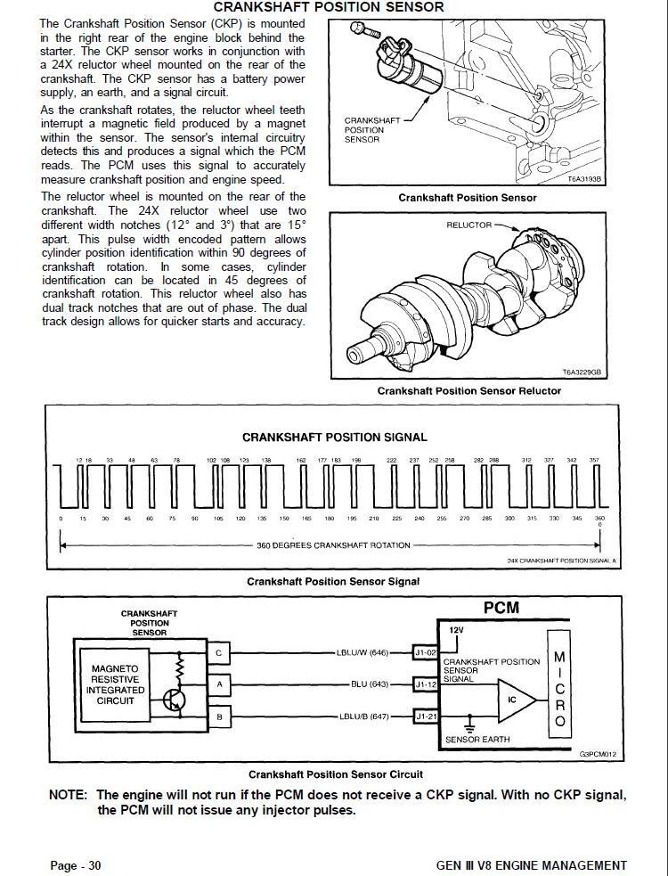
The crankshaft position (CKP) sensor is located in the right rear of the engine, behind the starter. The CKP sensor is a dual magneto resistive type sensor. The dual micro switches monitor both notches of the reluctor wheel for greater accuracy. The CKP sensor works in-conjunction with a 24X reluctor wheel. The reluctor wheel is mounted on the rear of the crankshaft. The 24X reluctor wheel uses 2 different width notches that are 15 degrees apart. This pulse width encoded (PWE) pattern allows cylinder position identification within 90 degrees of crankshaft rotation. In some cases, cylinder identification can be located in 45 degrees of crankshaft rotation. This reluctor wheel also has dual track notches that are 180 degrees out of phase. The dual track design allows for quicker starts and accuracy.

The PCM also receives a 4X signal from the CKP sensor. The PCM utilizes the 4X signal for the following:

Misfire
Tachometer output
Spark control
Fuel control
Certain diagnostics
The CKP signal must be available for the engine to start. The CMP signal is not needed to start and operate the engine. The PCM can determine when a particular cylinder is on either a firing or exhaust stroke by the 24X signal. The CMP sensor is to determine what stroke the engine is on. The system will attempt synchronization and look for an increase in the MAF signal. An increase in the MAF signal indicates the engine has started. If the PCM does not detect an increase in the MAF signal, a re-sync will occur to the opposite cam position. A slightly longer cranking time may be a symptom of this condition.

Camshaft Position Sensor


The camshaft position (CMP) sensor is mounted through the top of the engine block at the rear of the valley cover. The CMP sensor works in conjunction with a 1X reluctor wheel. The reluctor wheel is located at the rear of the camshaft. The CMP sensor is used to determine whether a cylinder is on the firing or the exhaust stroke. As the camshaft rotates, the reluctor wheel interrupts a magnetic field produced by a magnet within the sensor. The CMP sensor internal circuitry detects this and produces a signal which is used by the PCM. The PCM uses this signal in combination with the CKP 24X signal to determine crankshaft position and stroke.

The CKP signal must be available for the engine to start. The CMP signal is not needed to start and operate the engine. The PCM can determine when a particular cylinder is on either a firing or exhaust stroke by the 24X signal. The CMP sensor is to determine what stroke the engine is on. The system will attempt synchronization and look for an increase in the MAF signal. An increase in the MAF signal indicates the engine has started. If the PCM does not detect an increase in the MAF signal, a re-sync will occur to the opposite cam position. A slightly longer cranking time may be a symptom of this condition.

Ignition Coils/Module


The ignition system on this vehicle features a multiple coil ignition and is known as coil near plug. The secondary ignition wires are short compared with a distributor ignition system wire. The 8 ignition coils/modules are individually mounted above each cylinder on the rocker covers. The coils/modules are fired sequentially. There is an ignition control (IC) circuit for each ignition coil/module. The 8 ignition control circuits are connected to the PCM. All timing decisions are made by the PCM, which triggers each coil/module individually. The ignition coil/modules are supplied with the following circuits:

Ignition feed circuit
Ignition control circuit
Ground circuit
Reference low circuit
The ignition feed circuits are fused separately for each bank of the engine. The 2 fuses also supply the injectors for that bank of the engine. Each coil/module is serviced separately.

This system puts out very high ignition energy for plug firing. Because the ignition wires are shorter, less energy is lost to ignition wire resistance. Also, since the firing is sequential, each coil has seven events to saturate as opposed to the three in a waste spark arrangement. Futhermore, no energy is lost to the resistance of a waste spark system.

Circuits Affecting Ignition Control
To properly control ignition timing, the PCM relies on the following information:

Engine load (manifold pressure or vacuum)
Atmospheric (barometric) pressure
Engine temperature
Intake air temperature
Crankshaft position
Engine speed (RPM)
The ignition control (IC) system consists of the following components:

Ignition coil/modules
24X crankshaft position sensor
Powertrain Control Module (PCM)
All connecting wires
The Ignition Control utilizes the following to control spark timing functions:

24X signal -- The 24X crankshaft position sensor sends a signal to the PCM. The PCM uses this signal to determine crankshaft position. The PCM also utilizes this signal to trigger the fuel injectors.
Ignition Control (IC) circuits -- The PCM uses these circuits to trigger the ignition coil/modules. The PCM uses the crankshaft reference signal to calculate the amount of spark advance needed.
Noteworthy Ignition Information
There are important considerations to point out when servicing the ignition system. The following noteworthy information will list some of these, to help the technician in servicing the ignition system.

The ignition coils secondary voltage output capabilities are very high -- more than 40,000 volts. Avoid body contact with ignition high voltage secondary components when the engine is running, or personal injury may result!
The 24X crankshaft position sensor is the most critical part of the ignition system. If the sensor is damaged so that pulses are not generated, the engine will not start!
Crankshaft position sensor clearance is very important! The sensor must not contact the rotating interrupter ring at any time, or sensor damage will result. If the interrupter ring is bent, the interrupter ring blades will destroy the sensor.
Ignition timing is not adjustable. There are no timing marks on the crankshaft balancer or timing chain cover.

Important
Never pierce a secondary ignition wire or boot for any testing purposes.


Be careful not to damage the secondary ignition wires or boots when servicing the ignition system. Rotate each boot to dislodge it from the plug or coil tower before pulling it from either a spark plug or the ignition coil. Future problems are guaranteed if pinpoints or test lights are pushed through the insulation for testing.
Powertrain Control Module (PCM)
The PCM is responsible for maintaining proper spark and fuel injection timing for all driving conditions. To provide optimum driveability and emissions, the PCM monitors input signals from the following components in calculating ignition control (IC) spark timing:

Engine Coolant Temperature (ECT) sensor
Intake Air Temperature (IAT) sensor
Mass Air Flow (MAF) sensor
Knock Sensor
Trans Range inputs from Transaxle Range switch
Throttle Position (TP) sensor
Vehicle Speed Sensor (VSS)
Results of Incorrect Operation
An Ignition control circuit that is open, grounded, or short to voltage will set an ignition control circuit DTC. If a fault occurs in the IC output circuit when the engine is running, the engine will experience a misfire. DTCs P0351-P0358 will set when a malfunction is detected with an Ignition Control circuit. When an Ignition control DTC sets, the PCM will disabled the injector for the appropriate cylinder.

The PCM uses information from the engine coolant temperature sensor in addition to RPM to calculate spark advance values as follows:

High RPM = more advance
Cold engine = more advance
Low RPM = less advance
Hot engine = less advance
Therefore, detonation may be caused by high resistance in the engine coolant temperature sensor circuit. Poor performance may be caused by low resistance in the engine coolant temperature sensor circuit.

If the engine cranks but will not run or immediately stalls, Engine Cranks But Will Not Run diagnostic table must be used to determine if the failure is in the ignition system or the fuel system. If DTC P0300, P0341, P0342, P0343, P0335, P0336 is set, the appropriate diagnostic trouble code table must be used for diagnosis.


--------------------------------------------------------------------------------

[This message has been edited by AJxtcman (edited 02-09-2011).]

IP: Logged
AJxtcman
Member
Posts: 1098
From: Rock Hill SC
Registered: Nov 2006


Feedback score: N/A
Leave feedback

Rate this member

Report this Post12-08-2007 10:00 AM Click Here to See the Profile for AJxtcmanSend a Private Message to AJxtcmanDirect Link to This Post

AJxtcman

1098 posts
Member since Nov 2006
2000 to 2003 Cadillac
Electronic Ignition (EI) System
Ignition System Overview
The electronic ignition system controls fuel combustion by providing a spark to ignite the compressed air/fuel mixture at the correct time. To provide optimum engine performance, fuel economy, and control of exhaust emissions, the PCM controls the ignition system. The electronic ignition system has the following advantages over a mechanical distributor system:

No moving parts
Less maintenance
Remote mounting capability
No mechanical load on the engine
More coil cool down time between firing events
Elimination of mechanical timing adjustments
Increased available ignition coil saturation time
Operation
The electronic ignition system does not use the conventional distributor and coil. The ignition system consists of the following components/circuits:

Eight ignition coils
Eight ignition control (IC) circuits
Two ignition control modules (one per cylinder bank)
Camshaft position (CMP) sensor
Crankshaft position (CKP) sensor A
Crankshaft position (CKP) sensor B
Related connecting wires
Powertrain control module (PCM)
Crankshaft Position Sensors
The PCM uses dual crankshaft position (CKP A and CKP B) sensors to determine crankshaft position. The CKP sensors are mounted in the engine block approximately 21.5 degrees apart from each other. Three wires connect each CKP sensor to the PCM. The PCM supplies an ignition voltage and a ground for each CKP sensor. During engine rotation, a slotted ring, machined into the crankshaft, causes the sensors to return a series of ON and OFF pulses to the PCM. The PCM uses these pulses to decode the position of the engine crankshaft.

The PCM uses two basic methods of decoding the engine position: Angle Based and Time Based (using either CKP A or CKP B sensor input). During normal operation, the PCM uses the angle based method. In order to operate in this mode, the PCM must receive signal pulses from both CKP sensors. The PCM uses the signal pulses to determine an initial crankshaft position, and to generate MEDRES (24X reference) and LORES (4X reference) signals. Once the initial crank position is determined, the PCM continuously monitors both sensors for valid signal inputs. As long as both signal inputs remain, the PCM will continue to use the angle based mode.

When either CKP signal is lost, the PCM will compare the MEDRES signal to the camshaft position (CMP) sensor signal. If the PCM detects a valid CMP signal, and the MEDRES to CMP signal correlation is correct, the PCM determines that CKP sensor A is at fault. However, if the MEDRES to CMP correlation is incorrect, the PCM determines that CKP sensor B is at fault.

If the PCM detects a loss of signal for CKP sensor A, DTC P0335 will set. The PCM will switch from angle based mode to Time Based mode B using CKP sensor B signal input. If the PCM detects a loss of signal for CKP sensor B, DTC P0385 will set. The PCM will switch from angle based mode to Time Based mode A using CKP sensor B signal input. A noisy signal input from either CKP sensor will cause the ignition system to re-sync. If the number of ignition system re-sync is more than a calibrated amount, DTC P1372 will set.

Camshaft Position Sensor
The camshaft position (CMP) sensor is mounted in the front of the right cylinder head assembly. The CMP sensor signal, when combined with the CKP sensor signal, enables the PCM to determine exactly which cylinder is on a firing stroke. The PCM can then properly synchronize the ignition system, fuel injectors and knock control. The PCM supplies an ignition voltage and a ground for the CMP sensor. If a problem is detected with the CMP circuit, DTC P0340 or P0341 will set.

Ignition Coils/Modules
The electronic ignition system uses an individual ignition coil for each cylinder. There are two separate ignition module assemblies located in the camshaft cover of each cylinder bank. Each ignition module assembly contains an ignition control module and four ignition coils. Each ignition coil connects directly to a spark plug using a boot. This arrangement eliminates the need for secondary ignition wires. The ignition module assemblies receive power from a fused ignition feed. Both ignition module assemblies connect to chassis ground. A Reference Low and four ignition control (IC) circuits connect each ignition module assembly to the PCM. The PCM uses the individual IC circuits to control coil sequencing and spark timing for each ignition coil. The IC circuits transmit timing pulses from the PCM to the ignition control module to trigger the ignition coil and fire the spark plug. The PCM controls ignition system sequencing and timing events.

This ignition system produces very high energy to fire the spark plug. There is no energy loss because of ignition wire resistance, or the resistance of the waste spark system. Also, since the firing is sequential, each coil has seven ignition events to saturate as opposed to the three in a waste spark arrangement.

Noteworthy Ignition Information
There are important considerations to point out when servicing the ignition system. The following noteworthy information will list some of these, to help the technician in servicing the ignition system.

The ignition coils secondary voltage output capabilities are very high - more than 40,000 volts. Avoid body contact with ignition high voltage secondary components when the engine is running, or personal injury may result!
The crankshaft position sensor clearance is very important! The sensor must not contact the reluctor wheel at any time, or sensor damage will result. If the reluctor wheel contacts the sensors, destruction of the sensors will occur.
Ignition timing is not adjustable. There are no timing marks on the crankshaft pulley.
If a boot remains attached to a coil or spark plug, twist the boot prior to removal using the correct tool. Do not use pliers, screwdrivers, or any unauthorized tools to remove the boot.
Check the boot for a missing or damaged internal spring.
Do not re-install any component that has visible signs of damage.
Install the boots onto the coils (until bottomed out). Then install the assembly onto the spark plugs. If this is not possible due to space limitations, just-start the boots onto the spark plugs and then install the coil assembly as straight down onto the plugs as possible.
Ensure the boots are installed right side up.
Repair a torn perimeter seal with RTV sealant.
Adhere to the torque specifications when installing the cassette to the cam cover and the module to the cassette.
Powertrain Control Module (PCM)
The PCM is responsible for maintaining proper spark and fuel injection timing for all driving conditions. To provide optimum driveability and emissions, the PCM monitors input signals from the following components in calculating ignition control (IC) spark timing:

Engine coolant temperature (ECT) sensor
Intake air temperature (IAT) sensor
Mass air flow (MAF) sensor
Trans range inputs from transaxle range switch
Throttle position (TP) sensor
Vehicle speed sensor (VSS)
Reference Low Circuits
The reference low circuits provide a common ground between the PCM, and the ignition control modules. These circuits reduce the electrical ground shifts that may occur between the PCM and the ignition control modules. A malfunction in the reference low circuits may cause a poor driveability condition.

Results of Incorrect Operation
An Ignition control circuit that is open, grounded, or short to voltage will set an ignition control circuit DTC. If a fault occurs in the IC output circuit when the engine is running, the engine will experience a misfire. DTCs P0351-P0358 indicate that a malfunction has been detected on an Ignition Control circuit. DTCs P1359 and P1360 will set when the PCM detects random malfunctions in ignition control circuit.


--------------------------------------------------------------------------------
IP: Logged
AJxtcman
Member
Posts: 1098
From: Rock Hill SC
Registered: Nov 2006


Feedback score: N/A
Leave feedback

Rate this member

Report this Post12-08-2007 10:02 AM Click Here to See the Profile for AJxtcmanSend a Private Message to AJxtcmanDirect Link to This Post

AJxtcman

1098 posts
Member since Nov 2006
 
quote
Originally posted by AJxtcman:

2000 to 2003 Cadillac
Electronic Ignition (EI) System

The PCM uses two basic methods of decoding the engine position: Angle Based and Time Based (using either CKP A or CKP B sensor input). During normal operation, the PCM uses the angle based method. In order to operate in this mode, the PCM must receive signal pulses from both CKP sensors. The PCM uses the signal pulses to determine an initial crankshaft position, and to generate MEDRES (24X reference) and LORES (4X reference) signals. Once the initial crank position is determined, the PCM continuously monitors both sensors for valid signal inputs. As long as both signal inputs remain, the PCM will continue to use the angle based mode.


Hmm ?
IP: Logged
AJxtcman
Member
Posts: 1098
From: Rock Hill SC
Registered: Nov 2006


Feedback score: N/A
Leave feedback

Rate this member

Report this Post12-19-2007 07:30 PM Click Here to See the Profile for AJxtcmanSend a Private Message to AJxtcmanDirect Link to This Post
The car is running on this program very well. Now I need to swicth the Trans PCM over to a different on and I should post a video and some data logging info
IP: Logged
PFF
System Bot
AJxtcman
Member
Posts: 1098
From: Rock Hill SC
Registered: Nov 2006


Feedback score: N/A
Leave feedback

Rate this member

Report this Post12-19-2007 07:49 PM Click Here to See the Profile for AJxtcmanSend a Private Message to AJxtcmanDirect Link to This Post

AJxtcman

1098 posts
Member since Nov 2006
I have had a realy bad cold for the last three weeks. Now my Girlfriend is in the hospital. She had back sugery and they had an issue and cut one of the big arteries that goes to her legs. Either the left or the one for the right leg. She has lost a lot of blood and has internal bleeding still. It has been two days. Life is realy busy and I have to take care of three kids. Good news The cold is almost gone and I feel great.
IP: Logged
Dave E Bouy
Member
Posts: 1465
From: Kettle Point Ontario Canada
Registered: Sep 2004


Feedback score:    (6)
Leave feedback

Rate this member

Report this Post12-19-2007 08:41 PM Click Here to See the Profile for Dave E BouySend a Private Message to Dave E BouyDirect Link to This Post
 
quote
Originally posted by AJxtcman:

I have had a realy bad cold for the last three weeks. Now my Girlfriend is in the hospital. She had back sugery and they had an issue and cut one of the big arteries that goes to her legs. Either the left or the one for the right leg. She has lost a lot of blood and has internal bleeding still. It has been two days. Life is realy busy and I have to take care of three kids. Good news The cold is almost gone and I feel great.


Wow you have a lot going on. Hope all goes well with your girlfriend that sounds nasty. Take care

Dave
IP: Logged
AJxtcman
Member
Posts: 1098
From: Rock Hill SC
Registered: Nov 2006


Feedback score: N/A
Leave feedback

Rate this member

Report this Post12-19-2007 10:38 PM Click Here to See the Profile for AJxtcmanSend a Private Message to AJxtcmanDirect Link to This Post
 
quote
Originally posted by Dave E Bouy:


Wow you have a lot going on. Hope all goes well with your girlfriend that sounds nasty. Take care

Dave


Did I meet you at the Dells?
IP: Logged
IXSLR8
Member
Posts: 673
From: Post Falls, ID, USA
Registered: Sep 2004


Feedback score: (1)
Leave feedback

Rate this member

Report this Post12-20-2007 03:27 AM Click Here to See the Profile for IXSLR8Send a Private Message to IXSLR8Direct Link to This Post
Hey, hope everything goes well with you. Hope your girl heals up fast too and that you all recover quickly. Perhaps you'll get some time to relax during the holidays. We'll all be waiting to hear how its going with the LS1 pcm when the time is right for you.
IP: Logged
Dave E Bouy
Member
Posts: 1465
From: Kettle Point Ontario Canada
Registered: Sep 2004


Feedback score:    (6)
Leave feedback

Rate this member

Report this Post12-22-2007 09:14 AM Click Here to See the Profile for Dave E BouySend a Private Message to Dave E BouyDirect Link to This Post
 
quote
Originally posted by AJxtcman:


Did I meet you at the Dells?


Nope not me. I've never been to the Dells but I'd like to!!!!!! Enjoy the holidays AJ

Dave
IP: Logged
motoracer838
Member
Posts: 3751
From: Edgewater Co. USofA
Registered: Jan 2006


Feedback score: (2)
Leave feedback


Total ratings: 83
Rate this member

Report this Post12-22-2007 10:25 AM Click Here to See the Profile for motoracer838Send a Private Message to motoracer838Direct Link to This Post
I'm sorry to hear how things are going for you, I hope everythings getting better.

Joe
IP: Logged
AJxtcman
Member
Posts: 1098
From: Rock Hill SC
Registered: Nov 2006


Feedback score: N/A
Leave feedback

Rate this member

Report this Post12-24-2007 02:43 PM Click Here to See the Profile for AJxtcmanSend a Private Message to AJxtcmanDirect Link to This Post
Insane Fast
IP: Logged
AJxtcman
Member
Posts: 1098
From: Rock Hill SC
Registered: Nov 2006


Feedback score: N/A
Leave feedback

Rate this member

Report this Post12-25-2007 06:29 PM Click Here to See the Profile for AJxtcmanSend a Private Message to AJxtcmanDirect Link to This Post
I hurt my trans. Way to much power
IP: Logged
motoracer838
Member
Posts: 3751
From: Edgewater Co. USofA
Registered: Jan 2006


Feedback score: (2)
Leave feedback


Total ratings: 83
Rate this member

Report this Post12-25-2007 09:39 PM Click Here to See the Profile for motoracer838Send a Private Message to motoracer838Direct Link to This Post
 
quote
Originally posted by AJxtcman:

I hurt my trans. Way to much power


You hurt a 4T80e?

Joe

[This message has been edited by motoracer838 (edited 12-25-2007).]

IP: Logged
Zac88GT
Member
Posts: 1024
From: Victoria BC
Registered: Nov 2004


Feedback score: N/A
Leave feedback

Rate this member

Report this Post12-26-2007 01:07 AM Click Here to See the Profile for Zac88GTClick Here to visit Zac88GT's HomePageSend a Private Message to Zac88GTDirect Link to This Post
 
quote
Originally posted by motoracer838:

You hurt a 4T80e?

Joe


And with a stock engine?

[This message has been edited by Zac88GT (edited 12-26-2007).]

IP: Logged
PFF
System Bot
AJxtcman
Member
Posts: 1098
From: Rock Hill SC
Registered: Nov 2006


Feedback score: N/A
Leave feedback

Rate this member

Report this Post12-26-2007 07:17 PM Click Here to See the Profile for AJxtcmanSend a Private Message to AJxtcmanDirect Link to This Post
I shot a short video. I just bought an old camcorder. It is not what I wanted at all, but it was $70. It is a ES100V. Bad thing it is a Hi8. So I upload the video to my Tivo. I saved it to disc. I put it in my PC and can't copy it. ugh. I have a nice video card in my PC, but a own a Video capture card. That card only had 64mb memory on it. I paid a lot of cash for the video capture card, but I used to game and it was just a tad bit slower. My PC is just ok, but when I built it the power unit was just the right size. I have added so much that it over loaded it and my Mother board has been damaged. I changed the power unit last year, but if I shut of my PC it may not start. I have to unplug everything, but the MB and hard drive. It still takes an hour or so to get it going again. This leads me to my delema. If I change my Video card it my take a MB.

Well I will be signing out and hope to be back up.
IP: Logged
AJxtcman
Member
Posts: 1098
From: Rock Hill SC
Registered: Nov 2006


Feedback score: N/A
Leave feedback

Rate this member

Report this Post12-27-2007 09:51 PM Click Here to See the Profile for AJxtcmanSend a Private Message to AJxtcmanDirect Link to This Post
No sound.
what next.
Gone

[This message has been edited by AJxtcman (edited 12-28-2007).]

IP: Logged
philbur120
Member
Posts: 221
From: Sarnia, Ontario, Canada
Registered: Jul 2006


Feedback score: (1)
Leave feedback

Rate this member

Report this Post12-27-2007 10:58 PM Click Here to See the Profile for philbur120Send a Private Message to philbur120Direct Link to This Post
Lookin good AJ.
Cant wait to get this set up for my northstar.

Phil
IP: Logged
AJxtcman
Member
Posts: 1098
From: Rock Hill SC
Registered: Nov 2006


Feedback score: N/A
Leave feedback

Rate this member

Report this Post12-28-2007 02:32 PM Click Here to See the Profile for AJxtcmanSend a Private Message to AJxtcmanDirect Link to This Post
I fixed the sound

[This message has been edited by AJxtcman (edited 01-02-2008).]

IP: Logged
AJxtcman
Member
Posts: 1098
From: Rock Hill SC
Registered: Nov 2006


Feedback score: N/A
Leave feedback

Rate this member

Report this Post01-02-2008 07:58 PM Click Here to See the Profile for AJxtcmanSend a Private Message to AJxtcmanDirect Link to This Post


New Video It was tooooooo looooong so I had to cut it up.
IP: Logged
AJxtcman
Member
Posts: 1098
From: Rock Hill SC
Registered: Nov 2006


Feedback score: N/A
Leave feedback

Rate this member

Report this Post01-02-2008 08:19 PM Click Here to See the Profile for AJxtcmanSend a Private Message to AJxtcmanDirect Link to This Post

AJxtcman

1098 posts
Member since Nov 2006
 
quote
Originally posted by AJxtcman:


New Video It was tooooooo looooong so I had to cut it up.


The front lifts way up
IP: Logged
AJxtcman
Member
Posts: 1098
From: Rock Hill SC
Registered: Nov 2006


Feedback score: N/A
Leave feedback

Rate this member

Report this Post01-02-2008 11:41 PM Click Here to See the Profile for AJxtcmanSend a Private Message to AJxtcmanDirect Link to This Post

AJxtcman

1098 posts
Member since Nov 2006
all this screwing around I lost my speedo. The LS1 PCM thinks I am doning 158 at 40mph and the Northstar PCM that runs the trans is not giving me a speedo output. It shifts the car fine and at the correct speeds, but I do not have it hooked up to a DLC so I have no info from it. I think it does not think that it is running. I did not connect a PK3 bypass module to it. Hmmmmmmmmmm. I have no heater yet. 11° out. Hmmmm
IP: Logged
IXSLR8
Member
Posts: 673
From: Post Falls, ID, USA
Registered: Sep 2004


Feedback score: (1)
Leave feedback

Rate this member

Report this Post01-03-2008 06:06 AM Click Here to See the Profile for IXSLR8Send a Private Message to IXSLR8Direct Link to This Post
Very nice!

So, now that you have had a chance to use the LS1, do you prefer the LS1 computer with your present configuration over the others out there that you've run the N* with?
IP: Logged
AJxtcman
Member
Posts: 1098
From: Rock Hill SC
Registered: Nov 2006


Feedback score: N/A
Leave feedback

Rate this member

Report this Post01-03-2008 07:17 AM Click Here to See the Profile for AJxtcmanSend a Private Message to AJxtcmanDirect Link to This Post
 
quote
Originally posted by IXSLR8:

Very nice!

So, now that you have had a chance to use the LS1, do you prefer the LS1 computer with your present configuration over the others out there that you've run the N* with?


Edited to the next post

[This message has been edited by AJxtcman (edited 01-03-2008).]

IP: Logged
AJxtcman
Member
Posts: 1098
From: Rock Hill SC
Registered: Nov 2006


Feedback score: N/A
Leave feedback

Rate this member

Report this Post01-03-2008 08:38 AM Click Here to See the Profile for AJxtcmanSend a Private Message to AJxtcmanDirect Link to This Post

AJxtcman

1098 posts
Member since Nov 2006
This will help.
Rolling start with a stock PCM vs a Standing start with a LS1 PCM.
Look at the starting spot and count the poles until 3rd gear

[This message has been edited by AJxtcman (edited 03-05-2008).]

IP: Logged
PFF
System Bot
AJxtcman
Member
Posts: 1098
From: Rock Hill SC
Registered: Nov 2006


Feedback score: N/A
Leave feedback

Rate this member

Report this Post01-04-2008 09:08 PM Click Here to See the Profile for AJxtcmanSend a Private Message to AJxtcmanDirect Link to This Post
I have a blower now.
IP: Logged
AJxtcman
Member
Posts: 1098
From: Rock Hill SC
Registered: Nov 2006


Feedback score: N/A
Leave feedback

Rate this member

Report this Post01-09-2008 08:43 PM Click Here to See the Profile for AJxtcmanSend a Private Message to AJxtcmanDirect Link to This Post


Hmmm

Guess what is done?

[This message has been edited by AJxtcman (edited 01-09-2008).]

IP: Logged
AJxtcman
Member
Posts: 1098
From: Rock Hill SC
Registered: Nov 2006


Feedback score: N/A
Leave feedback

Rate this member

Report this Post01-09-2008 09:07 PM Click Here to See the Profile for AJxtcmanSend a Private Message to AJxtcmanDirect Link to This Post

AJxtcman

1098 posts
Member since Nov 2006
IP: Logged
THE BEAST
Member
Posts: 1177
From: PORT SAINT LUCIE,FLORIDA,USA
Registered: Dec 2000


Feedback score: N/A
Leave feedback

Rate this member

Report this Post01-10-2008 01:18 PM Click Here to See the Profile for THE BEASTSend a Private Message to THE BEASTDirect Link to This Post
AJ I can't find my getrag speed sensor gear-wheel, and by the way looking good there!

JG
IP: Logged
AJxtcman
Member
Posts: 1098
From: Rock Hill SC
Registered: Nov 2006


Feedback score: N/A
Leave feedback

Rate this member

Report this Post01-10-2008 04:18 PM Click Here to See the Profile for AJxtcmanSend a Private Message to AJxtcmanDirect Link to This Post
LS1 stock


LS1 adjustable


Stock PCM with the Torque Management set higher.


Stock PCM that I got the torque set higher on
IP: Logged
Hulk
Member
Posts: 615
From:
Registered: Oct 2004


Feedback score: N/A
Leave feedback

Rate this member

Report this Post01-11-2008 03:27 AM Click Here to See the Profile for HulkSend a Private Message to HulkDirect Link to This Post
 
quote
Originally posted by AJxtcman:

This will help.
Rolling start with a stock PCM vs a Standing start with a Shelby/LS1 PCM.
Look at the starting spot and count the poles until 3rd gear


Impressive work!

Forgive me, but I'm dense, I guess. It appears in your vid that the setup allows you to wind out the RPMs more, but can't we do that with the current '96 - '99 ECMs, like the one I got from Ryan? I do see an immediate advantage in that the newer N*s can now be used, without resorting to some stupidly expensive system like FAST...

[This message has been edited by Hulk (edited 01-11-2008).]

IP: Logged
AJxtcman
Member
Posts: 1098
From: Rock Hill SC
Registered: Nov 2006


Feedback score: N/A
Leave feedback

Rate this member

Report this Post01-11-2008 06:34 AM Click Here to See the Profile for AJxtcmanSend a Private Message to AJxtcmanDirect Link to This Post
This comes with tuning software, service manual,

[This message has been edited by AJxtcman (edited 03-05-2008).]

IP: Logged
AJxtcman
Member
Posts: 1098
From: Rock Hill SC
Registered: Nov 2006


Feedback score: N/A
Leave feedback

Rate this member

Report this Post01-12-2008 01:46 AM Click Here to See the Profile for AJxtcmanSend a Private Message to AJxtcmanDirect Link to This Post
My car weighed in at 2710 lbs
IP: Logged
IXSLR8
Member
Posts: 673
From: Post Falls, ID, USA
Registered: Sep 2004


Feedback score: (1)
Leave feedback

Rate this member

Report this Post01-12-2008 01:53 AM Click Here to See the Profile for IXSLR8Send a Private Message to IXSLR8Direct Link to This Post
AJ, do you have all the bugs worked out to your liking for the getrag and the LSI?
IP: Logged
Previous Page | Next Page

This topic is 7 pages long:  1   2   3   4   5   6   7 


All times are ET (US)

T H I S   I S   A N   A R C H I V E D   T O P I C
  

Contact Us | Back To Main Page

Advertizing on PFF | Fiero Parts Vendors
PFF Merchandise | Fiero Gallery | Ogre's Cave
Real-Time Chat | Fiero Related Auctions on eBay


Copyright (c) 1999, C. Pennock