Please tell me what these connectors and wires are because they aren't on the pinout (which probably means that they should be deleted).
This pink wire went to the big 2x4" rectangular connector that is being deleted. It goes into the coil pack. I don't know where the end I cut off the connector goes.
The wires from this one go to the large rectangular connector, to the trans connectors (deleted for Getrag), etc.
Here's a connector off of the one above.
Another
Another
This one goes all the way to the big rectangular connector. There's a brown wire and the black one is a ground.
This one has four big wires and they all go down to the big rectangular connector.
What are these? I think they both have vacuum nipples on the bottom.
This is a knock sensor that doesn't fit in the socket. The one on the other side of the engine fits.
There is a pink wire that splits off and goes to all 6 injectors. It went into the big rectangular connector. Now where does it go?
I appreciate the help.
[This message has been edited by Rolling Thunder (edited 12-17-2010).]
first picture. The pink wire is your ignition wire. on some they go to the pcm and others to the fuse box. I hooked mine to the pcm pink wire that goes to the 203 connector under the center concole.
IP: Logged
06:55 PM
phonedawgz Member
Posts: 17106 From: Green Bay, WI USA Registered: Dec 2009
Split the injectors between the front bank and the rear bank. Use the existing wire for one bank and a new wire for the other bank. These two wires run to C203 to receive power from the fuses INJ1 and INJ2 The pins they connect to are C203 Pin J and Pin K. If you have a 4 cylinder donor car you will need to install a fuse in INJ2.
[This message has been edited by phonedawgz (edited 12-17-2010).]
Pink wire from the coil pack goes to the same place the pink wire from the coil went to on your 2.8 - that is it connects to E3 of C500. That is B+ feed to the ignition.
[This message has been edited by phonedawgz (edited 12-17-2010).]
the picture under the knock sensor picture. those are the starter wires. The purple one goes to the small bolt on the starter solenoid and the red one goes to the big bolt on the starter solenoid.
[This message has been edited by fierofan25 (edited 12-17-2010).]
Split the injectors between the front bank and the rear bank. Use the existing wire for one bank and a new wire for the other bank. These two wires run to C203 to receive power from the fuses INJ1 and INJ2 The pins they connect to are C203 Pin J and Pin K. If you have a 4 cylinder donor car you will need to install a fuse in INJ2.
So, cylinders 1-3 (rear) will be INJ2 and cylinders 4-6 (front) will be INJ1. I believe all injectors have 1 pink and 1 black wire. So, I need to split the 7 (I think) pink wires into INJ1 and INJ2? (INJ1&2 each splice into three wires that go to injectors... to make 8 wires in two separate circuits of 4 wires?)
quote
Originally posted by fierofan25:
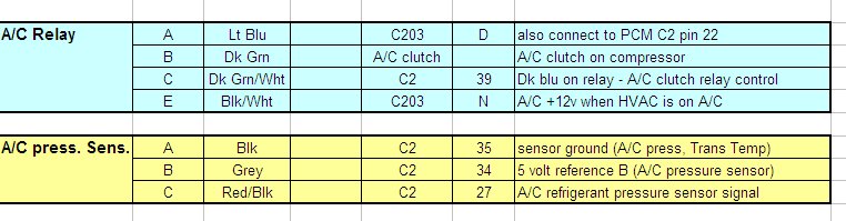
most of the other plugs are for the automatic transmission or A/C
I will have A/C, so I'll need to figure out which ones are A/C. I believe I have 2 A/C connectors already identified (not in the pictures).
I will have A/C, so I'll need to figure out which ones are A/C. I believe I have 2 A/C connectors already identified (not in the pictures).
Yes exactly like the 2.8 set up. One feed to three injectors. And then that duplicated. Look at your 2.8 harness. It's on the injector harness of the 2.8 that you see the split. The idea of the two seperate fuses is that if you happen to have a short or bad injector, you only loose half the engine however it still will run.
IP: Logged
09:27 PM
Rolling Thunder Member
Posts: 1244 From: College Station, TX Registered: Aug 2008