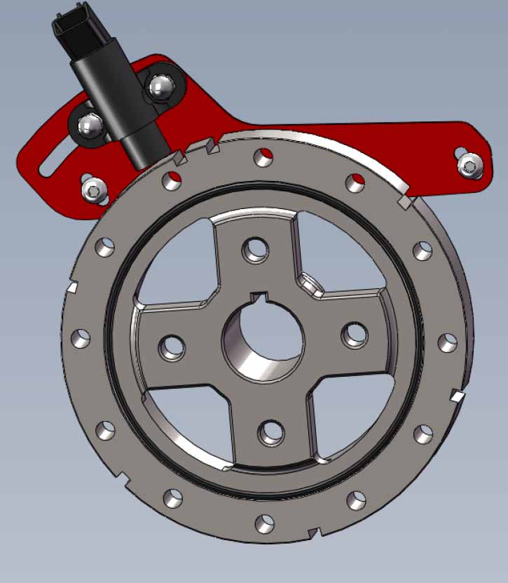
This thread is going to be a step by step guide to install a distributorless ignition setup on to a stock 2.8L V6 engine. A previous thread covered the work in progress. A lot changed on the way so I thought I would put the final setup all in one place. Here is what you need to do the conversion: 1 complete DIS coil pack including three coils, the module, and the mounting plate from a 90's vintage GM car. Mine came off of a Grand Am at the local "U Pull R Parts". The cost was $16.00. Be sure to get the three connectors and as much of a pig tail on them as you can. 1 Ford Crank Position Sensor from a '91 to '00 Escort or Tracer with the connector. You can also get this new as Standard Motor Products # PC-19 sensor and # S-819 connector. See the pics to see the one to get. 1 modified Harmonic Damper. Either the one you have now or a new Fiero or Camaro damper for the 2.8L. 1 Sensor mounting bracket made from the pattern in this thread. Some misc. nuts and bolts, wires, sleeving, and solder. Approximatly 4' of two conductor, twisted cable with shield braid. Must be rated for engine compartment temps. Here is a diagram of the set up at the damper:
The sensor bracket replaces the factory assembly line timing bracket and uses the same mounting holes in the timing cover.
More to follow.
- Tim
IP: Logged
12:33 PM
PFF
System Bot
Gravitic Anomaly Member
Posts: 137 From: Central MN, USA Registered: Jul 2007
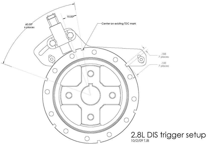
Start with the damper modification and sensor mounting. This will be much easier to do if the engine is out of the car but can be done with the engine in place. To do this jack up the passanger rear and remove the wheel. Then remove the inner wheel well liner to gain access to the damper. Turn the engine to TDC of cyliner #1, then remove the alternator and AC belts. Remove the pully on the damper and then use a damper puller to remove the damper. If you are going to re-use the damper give it a close inspection for damage or for rotting of the rubber ring. Check the area the timing cover seal runs on for grooving. Clean up any rust or gunk. You can also use a new Fiero damper or a Camaro damper. The damper needs to be modified to add 6 slots for triggering the sparks, plus one slot to syncronize the ignition module. On Fiero dampers the first slot is centered on the existing TDC mark on the damper outside diameter. Five more slots need to be placed evenly spaced at 60 degree intervals. The seventh slot gets placed at 10 degrees after (counter clockwise) of the slot at TDC. If you are going to use a Camaro damper you have a few extra steps. The Camaro damper is set up to rotate in the opposite direction as the fiero. You have to carefully line up the keyways of the Camaro damper and your Fiero damper and mark the TDC location of the Fiero damper onto the Camaro damper. Use this mark to locate the slots like on a fiero damper. After cutting the slots you will have to fill in the slots the Camaro damper came with. Fill these slots with steel and stake or tack weld into place. File down any steel or weld that is over the damper outside diameter. The best way to cut the slots you need it take the damper to a machinist along with the drawing in the next post and have them milled into the damper. Alternativly you can carefully cut the slots into the damper with a hacksaw and then file them to the final dimensions. Be certain to keep the slots perpendicular to the face of the damper and not skewed. Paint the damper. If your engine has any milage on it this is a great time to replace the timing cover seal. If you are re-using an old damper that has a groove in it from the seal you need to also install a sleeve for the new seal to run on. You can get this at the parts store.
More to follow...
-Tim
IP: Logged
01:21 PM
Gravitic Anomaly Member
Posts: 137 From: Central MN, USA Registered: Jul 2007
This drawing shows the location, depth and width of the seven slots. Center the first slot on the TDC mark on the damper. The drawing shows the damper as you face the engine.
[This message has been edited by Gravitic Anomaly (edited 10-05-2009).]
IP: Logged
01:32 PM
Gravitic Anomaly Member
Posts: 137 From: Central MN, USA Registered: Jul 2007
These are the patterns for the DIS sensor bracket. Print the pattern with printer scaling set to "none" or 100%. A scale is included to verify the pattern is printed to the correct size. Pick the file for the paper size you are using. "letter" for the US and "A4" for the rest of the world. The DXF file is for use with CNC equipment. I used 0.080" ( 2mm) thick, hard steel sheet to fabricate the part. The usual disclaimers apply. This has worked for me. Your experiance may vary. The files are offered "as-is". You are assuming all risks from there use. So there. Links are to an outside file service.
The next step is to prepare the sensor. The sensor comes with metal inserts in the mounting points. One of these has a smaller diameter hole and a stub protruding from the back of hte mounting surface. Cut off this stub and file it flat so the sensor will lie flat, then drill the hole out to the same size as the other hole. I used 1/4" carriage bolts to mount the sensor. Place them from the back side of the bracket so the square section engages the slot. This will hold the bolt from rotating when you tighten the nuts. If the square section protudes past the braket surface you will have to add washers under the bolt head or the sensor will not tighten up against the bracket. Place the sensor in place and hold with self locking nuts. Remove the assembly line timing bracket from the engine timing cover. It is held in place with security torx screws, the ones with the pin in the center. They are a PIA to remove. I ended up having to drill the head off of one of them. Set the sensor bracket in place and hold with new screws into the timing cover. Slide the sensor in the slot. You will see the head of one of the screws hits one of the ribs in the timing cover. Mark this spot. Remove the bracket and file the rib until the head will clear. remount the bracket. Pull it up so the bolts are at the bottom of there slots. Finger tighten bolts to hold the bracket in place.
More to follow...
-Tim
IP: Logged
01:59 PM
MordacP Member
Posts: 1300 From: Clovis, California, US Registered: Sep 2007
Time to re-install the damper. Put a little grease on the OD of the damper seal area. Line the keyway up with the key on the crankshaft and start the damper by pushing it onto the crankshaft. Install the damper all the way using a damper installation tool. These can usually be rented at the car parts store. Using this tool will prevent stripping the threads out on the crankshaft. You risk doing this if you just use the damper bolt to pull the damper down. Once the damper is in place put some silicon sealant into the keyway to prevent oil seepage past the key. Install the damper washer and bolt. Torque to spec. Check to ensure the engine is turned to TDC of #1 cylinder. Now position the sensor. If you are running a 7730 ECM set the sensor so it is centered in the first slot. This is the one where the original timing mark was. **If you have the original ECM set the sensor to 14 degrees after the slot.(experimental I have not tried this with the original ECM yet.)** Space the sensor .040" (1 mm) from the surface of the damper. Slide the sensor bracket on it's slots to do this. Tighten down the sensor nuts. Install the pully and the belts.
More to follow...
-Tim
[This message has been edited by Gravitic Anomaly (edited 10-05-2009).]
IP: Logged
02:39 PM
Gravitic Anomaly Member
Posts: 137 From: Central MN, USA Registered: Jul 2007
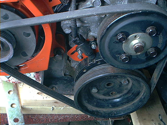
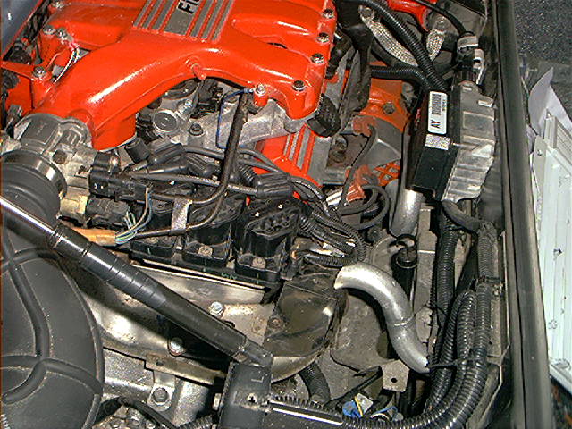
Now you need to decide where to mount the coil pack. I chose to place it in the location where the stock coil and distributor go. I was able to re-use the plug wires this way. Mounting on the trunk firewall could work as well but custom plug wires will be needed. In my set-up I removed the engine lifting eye from the rear cylinder bank. I fashioned a bracket from some angle iron and strap iron. It bolts into the holes left vacant by the lifting eye. The coil pack had to angle downward in the front slightly to clear the coolant tubes that go to the throttle body. I made some new heat shields and cut down the length of the blower air tube so the cold air blows under the coil pack.
More to follow...
-Tim
IP: Logged
03:30 PM
Gravitic Anomaly Member
Posts: 137 From: Central MN, USA Registered: Jul 2007
Depending on where you chose to mount your coil pack you can leave the distributor in place, or remove it. Removing it is isn't as simple as just plugging the hole up. The distributor gear drives the oil pump. It can be replaced with a "oil pump drive gear". This plugs into the distributor hole in the block and has the drive gear and oil pump shaft coupling on it. Basically it is the lower half of a distributor. Off hand I do not know which engines have a compatible oil pump drive gear. Hopefully someone can chime in with a suitable unit to use. Next time I am at the junk yard I hope to pick one up. Until then I modifed my old distributor. After disassembling it I cut the housing about 3" up from the mounting surface of the flange. Next I put the longer upper bushing into the gear end of my cut off housing. You have to turn or sand the first third of the bushing outside diameter so it doesn't get too tight. Install the bushing so the end is flush with the bottom of the housing. I drilled out and tapped the bore of the housing where I cut it off to fit a pipe plug. Do a good job of this. the plug will be under oil pressure and you do not want leaks. Next I cut the distributor shaft making sure it would not rub on the plug. Install the thrust washers and the shaft/gear assembly. Get a new o-ring for the housing. Get the brown silicone type, not a black viton ring. The viton rings will harden in this application and leak. Put the assembly into the hole in the block. Make sure the gear engages the cam shaft gear and the oil pump shaft. Clamp it down with the distributor clamp and bolt.
More to come....
-Tim
IP: Logged
05:25 PM
Patrick Member
Posts: 39414 From: Vancouver, British Columbia, Canada Registered: Apr 99
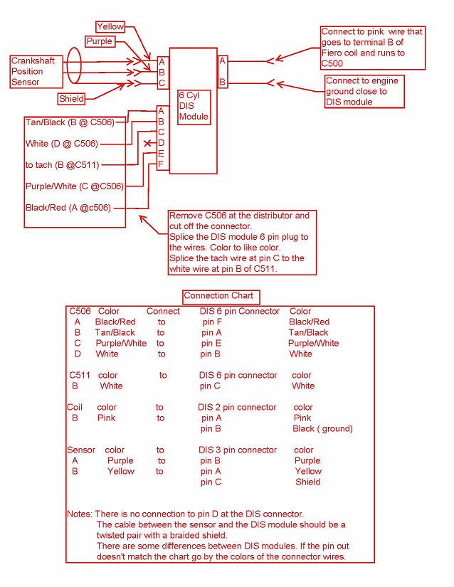
Thanks Blacktree! A camaro 3.4 dummy distributor it is. Here is a connection diagram for wiring it all up. Most of the wiring is already there. Cut the C506 connector off of the harness that plugs into the stock distributor ignition module. Slice these wires into the 6 pin connector for the DIS module. Color to like color. Take the tach wire from pin B of the C511 connector and splice it into the pin C white wire at the DIS module. Connect the pink wire from the coil connector to pin A of the 2 pin DIS connector, also pink. Connect the black DIS 2 pin connector wire to an engine ground close to the DIS module. Now make a sensor cable. The length will depend on just where you have mounted the coil pack. The wires need to be a twisted pair and need a braided shield over them. Connect one wire to Pin A on the sensor connector and one to pin B. There is no shield connection at the sensor end. Connect the wire you wired to pin A to the yellow wire on the 3 pin DIS connector. Connect the pin B wire to the purple wire at the DIS connector. Terminate the shield by soldering a wire to it and connecting this wire to the remaining DIS connector pin. Put split loom or sleeving over the cable. Route the cable from the sensor up behind the alternator belt and to your coil pack. Make certain it does not rub on anything. On my car I routed it under the intake alongside the injector harness.
OK, by now you have your modified damper, sensor, bracket, and coilpack in place and wired up. Next up is connecting the plug wires. In my setup I was able to re-use the old plug wires with a little rearranging. Depending on where you have mounted the coil pack you may need some longer wires. If you look at the coil pack from the plug tower side the three coils should be placed 2/5, 3/6, 1/4 reading left to right. Connect the plug wires 1 to 1, 2 to 2, ect. right on down the line. Since a coil fires both plugs it connects to at the same time it makes no difference which tower the wire goes to as long as it is on the correct coil. Double check all the wiring, mounting and such. Cross your fingers and start her up. The engine should turn at least one complete revolution for the DIS module to determine the crank location and then it will start to fire the coils. With the engine idleing immeadiatly check the oil pressure. If it's good then you can check for oil leaks at the distributor hole and any other problems. If the engine doesn't start, but just fire occasionally and will not run the first thing to check is the polarity of the crank position sensor signal. If this is backward the engine sputters a bit and acts like the ignition timing is way advanced. A firing cylinder might fight against the starter rotation. fix the problem by removing the 3 pin sensor plug at the DIS module and swap the yellow and puple wires. Plug it back in and try it again. If the engine still will not run, or runs rough, it is time to re-check all of the wiring. Check the plug wires to ensure they go to the correct cylinders. Check that the sensor got tightened down and is correctly gapped. Check the base timing is in the correct place. If it still runs rough or intermittently coughs or burps check that the sensor cable has the shield connected and is not grounding out on the engine anywhere. Try to re route the cable away from other wires.
Once you are satisfied the car is running ok it's time for a test drive. Take your cell phone with you and just go for a few short trips before going a long distance. Just in case.
Final thoughts and disclaimers. The modification I presented here is what I did to my car. So far it has worked for me. I do not warrant or claim it will work for you. I offer it as an experiment for the Fiero hobbist.
I am running a 7730 ECM with a re-programmed Memcal. In my opinion the 7730 ECM upgrade is one of the best things you can do for your cars drivability. I would swap the stock ECM out to a 7730 ECM before a DIS ignition swap. The 7730 upgrade is very well documented and you can get the Memcal programed by Darthfiero (GMTunners) at a reasonable price. The 7730 boxes are readily available.
If you are running a 7730 ECM with a DIS programmed Memcal you experiment with advancing the timing of the engine by moving the sensor on the bracket. This will shift the entire timing curve. At the sensor mounting bolts approximatly 0.070" (1.78mm) equals 1° of timing change.
If you are using the stock tachometer in the car you may or may not need the tach filter circuit. I have not tested the tach function with a stock instrument panel. My tach works without the filter but it is far from Fiero stock. I have a Grand Am instrument cluster with a Cavalier tach driver board.
As previously stated while I think this setup will work with a stock ECM and 14° base timing have not and do not plan to test it out. I you actually try it please let us all know how it has worked out for you.
-Tim
[This message has been edited by Gravitic Anomaly (edited 10-06-2009).]
IP: Logged
08:02 PM
Oct 6th, 2009
Cajun Member
Posts: 1616 From: Youngsville, La., USA Registered: Dec 2003
I believe it will. I do not have a car with a stock ECM to test it on so if some wants to experiment and report on the results that would be wonderful. Why do I think it will work? The distributor function, timing which cylinder to fire based on crankshaft position, happens in the DIS module. Not in the ECM. The ECM will not know if the engine has a DIS module or a HEI module. The difference is in the timing curve programmed into the Memcal. A stock ECM assumes the base timing is set at 14° BTC and retards the timing from there. A 7730 ECM with a Memcal programmed for DIS assumes the base timing is set at 0° . The bracket presented here will allow the sensor to be adjusted from 0° to 14° base timing. So a stock ECM with the base timing set to 14° BTC will run the engine. I do not know if the timing curve will be correct. My belife is it will be, but again this is an experiment for someone to try.
- Tim
IP: Logged
10:17 AM
Pyrthian Member
Posts: 29569 From: Detroit, MI Registered: Jul 2002
I thought it would work as well. but, in the original 7730 swap thread, I brought this up near the end of page 12, and they said NO. had to do with the actual pulse signals, which the ECM does use for injector timing tho, being batch fired, and with no actual fixed sequence - not sure why it would matter
IP: Logged
10:42 AM
Gravitic Anomaly Member
Posts: 137 From: Central MN, USA Registered: Jul 2007
The same signals to the ECM are present with either the HEI or DIS modules. You are even using the same 4 wires for the same four functions. The GM HEI module was such a sucess it was placed verbatim into the DIS module circuitry. The distributor function is actually a add on to the old HEI circuit. A trigger pulse goes to the ECM from the module and the ECM decides if it wants to adjust the timing or not. The only issue is if the the seventh "Sync" pulse is stripped off of the pulse train or not. It looks to me that it is. Knowing how engineering works I would say when the DIS module was developed it had to work stand alone with out changing the circuitry of the ECM. The ECM engineering was in a different department.
-Tim
IP: Logged
10:58 AM
Pyrthian Member
Posts: 29569 From: Detroit, MI Registered: Jul 2002
Does anyone know how to get ahold of Tim( Gravitic Anomaly )? He seems to be out of touch. I need to get the files he posted on Fileden. Any help would be most appreciated.
[This message has been edited by flimbob (edited 02-03-2010).]
Question: Instead of trying to find a machine shop to modify a harmonic balancer and cut a bracket, would it be possible to use a smaller custom-made reluctor wheel, mounted on the distributor shaft where the ignition rotor used to be? With the Ford crank sensor maybe mounted in the old cap?
I wonder if it's possible to add DIS to the earlier duke and still use the model 300 TBI, instead of switching over to the whole model 700 setup...
Originally posted by RWDPLZ: Question: Instead of trying to find a machine shop to modify a harmonic balancer and cut a bracket, would it be possible to use a smaller custom-made reluctor wheel, mounted on the distributor shaft where the ignition rotor used to be? With the Ford crank sensor maybe mounted in the old cap?
I wonder if it's possible to add DIS to the earlier duke and still use the model 300 TBI, instead of switching over to the whole model 700 setup...
yes - but - you must remember that the cam/dist turns at 1/2 the speed of the crank - so - you must double the marks on the spinning disc. and that includes the 10* TDC marker. but, I dont see this as any advantage. in fact - it seems like more work.
and, one of the main reasons for DIS is, as mentioned above - is clearing the way, so you can use the 3.4 Camaro intake
I was in the bonetard today, grabbed a dist "half shaft ". At the 5- 3.4 engines I looked at, NONE of them is using a crank "sensor" ! Where is the "Stock DIS" getting the "signal From ?