Pennock's Fiero Forum
  Technical Discussion & Questions - Archive
  Ignition module life & dwell on a 2.8L

T H I S   I S   A N   A R C H I V E D   T O P I C
  

Email This Page to Someone! | Printable Version


Ignition module life & dwell on a 2.8L by pmbrunelle
Started on: 09-02-2009 10:32 AM
Replies: 13
Last post by: pmbrunelle on 09-04-2009 01:04 PM
pmbrunelle
Member
Posts: 4619
From: Grand-Mère, Québec
Registered: Sep 2008


Feedback score: N/A
Leave feedback


Total ratings: 63
Rate this member

Report this Post09-02-2009 10:32 AM Click Here to See the Profile for pmbrunelleSend a Private Message to pmbrunelleDirect Link to This Post
I have an 85 GT V6, with manual transmission.
The engine is stock, except for ported exhaust manifolds.
I'm also running an aftermarket ECM, the MegaSquirt 2 kit.

Prior to installing MS this summer, I had a reliable ignition system.
Since installing MS, my ignition modules have had a habit of blowing.
Otherwise runs like a top.
This may be coincidental...

Since then, the distributor has been replaced with the new-design star-shaped one. (I had radial shaft play)
New cap+rotor.
AC Delco plugs.
Wires do not show arcing when sprayed with water.
Rebuilt tach filter.
New ignition coil, not AC Delco, some aftermarket OEM-style replacement:

It's not some high performance coil, although assuming it has OEM characteristics might be unwise...

This is the signal as seen at the coil's primary, on the tach terminal.
Here, the engine is idling at about 17" Hg of vac.

0.2V / div
0.5ms / div


I am not an ignition system expert...do I have too much coil saturation? Which may be causing the module to cook?

Any other theories?

IP: Logged
PFF
System Bot
Bloozberry
Member
Posts: 7760
From:
Registered: Jan 2009


Feedback score: N/A
Leave feedback


Total ratings: 311
Rate this member

Report this Post09-02-2009 03:10 PM Click Here to See the Profile for BloozberrySend a Private Message to BloozberryDirect Link to This Post
I'm no ignition system expert either, but my understanding of the ignition module (or Electronic Timing Module (EST)) is simply that of a high speed switch and reference sensor. There are only five circuits:

CCT 430 provides the ECM with engine RPM and crankshaft position
CCT 453 provides a common ground with the ECM;
CCT 424 the bypass circuit whereby the ECM switches control for ignition timing from the ECM module to the EST and vice versa;
CCT 423 is the trigger;

The fifth circuit is the primary field circuit in the coil, which when the current is switched on and off by the trigger, collapses the field in the primary coil inducing the high voltage in the secondary windings for the spark plugs. Being simply a reference sensor and trigger, I'm not sure how a bad coil would "cook" the EST. The EST does generate heat that neeeds to be dissipated through it's metal base which acts as a heat sink. You are supposed to use a special dielectric grease between the EST and the base of the distributor for good heat transfer as well as to maintain a good electrical contact between the dissimilar metals. Did you apply the grease when you installed the new module?

IP: Logged
Dodgerunner
Member
Posts: 9687
From: Lincoln, Nebraska
Registered: Sep 2004


Feedback score:    (61)
Leave feedback


Total ratings: 323
Rate this member

Report this Post09-02-2009 03:25 PM Click Here to See the Profile for DodgerunnerClick Here to visit Dodgerunner's HomePageSend a Private Message to DodgerunnerDirect Link to This Post
I second the heat sink grease. However, as Booz says, as the field collapses the in the primary of the coil it generates a reverse current to the excitation current. This needs someplace to go. Generally there is a diode that should conduct the current to ground.
It's possible that the coil creates a much higher current than the original coil and the circuit in the module can't take it for a long time and fails which would start a cascade affect to failure.

It might be possble to add a larger diode to the output between the module and the coil to ground adding an additional path for the current. You would connect the cathode (K) of the diode K --|<|-- A to the module output and the anode to ground. Might be worth a try. Or change the coil back.
IP: Logged
KurtAKX
Member
Posts: 4008
From: West Bloomfield, MI
Registered: Feb 2002


Feedback score:    (9)
Leave feedback


Total ratings: 128
Rate this member

Report this Post09-02-2009 03:45 PM Click Here to See the Profile for KurtAKXSend a Private Message to KurtAKXDirect Link to This Post
How many ms is the coil charging for?
IP: Logged
Erik
Member
Posts: 5628
From: Des Moines, Iowa
Registered: Jul 2002


Feedback score: (3)
Leave feedback


Total ratings: 168
Rate this member

Report this Post09-02-2009 03:56 PM Click Here to See the Profile for ErikSend a Private Message to ErikDirect Link to This Post
I would not use dielectric grease ..

use CPU heat transfer compound ..you can get it at Radio Shack
IP: Logged
gem1138
Member
Posts: 631
From: Baton Rouge, LA
Registered: Aug 2007


Feedback score: N/A
Leave feedback

Rate this member

Report this Post09-02-2009 04:12 PM Click Here to See the Profile for gem1138Send a Private Message to gem1138Direct Link to This Post
Absolutely, no dielectric grease!
IP: Logged
Austrian Import
Member
Posts: 3919
From: Monterey, CA
Registered: Feb 2007


Feedback score: N/A
Leave feedback

Rate this member

Report this Post09-02-2009 04:20 PM Click Here to See the Profile for Austrian ImportSend a Private Message to Austrian ImportDirect Link to This Post
Oh, crap. I think I have some dielectric grease on there. (no issues so far though)

I thought that it's the automotive equivalent of heat sink compound.
IP: Logged
Bloozberry
Member
Posts: 7760
From:
Registered: Jan 2009


Feedback score: N/A
Leave feedback


Total ratings: 311
Rate this member

Report this Post09-02-2009 04:39 PM Click Here to See the Profile for BloozberrySend a Private Message to BloozberryDirect Link to This Post
 
quote
Originally posted by Dodgerunner:

However, as Booz says


OK, I admit it... I have a drink every now & then... but certainly not enough to start calling me Booz.
IP: Logged
Erik
Member
Posts: 5628
From: Des Moines, Iowa
Registered: Jul 2002


Feedback score: (3)
Leave feedback


Total ratings: 168
Rate this member

Report this Post09-02-2009 05:31 PM Click Here to See the Profile for ErikSend a Private Message to ErikDirect Link to This Post
 
quote
Originally posted by Austrian Import:

Oh, crap. I think I have some dielectric grease on there. (no issues so far though)

I thought that it's the automotive equivalent of heat sink compound.


if its white or gray and opaque then its probably heat sink ..if its translucent then its most likely dielectric grease.
I have had a problem with autoparts stores having dielectric grease pakage in with a module and try to explain to them that it wont worka sits for moisture prevention and non conductivity NOT heat transfer
IP: Logged
Ditkaphile
Member
Posts: 816
From: Rockford, IL USA
Registered: Apr 2007


Feedback score: N/A
Leave feedback

Rate this member

Report this Post09-02-2009 07:02 PM Click Here to See the Profile for DitkaphileSend a Private Message to DitkaphileDirect Link to This Post
 
quote
Originally posted by Bloozberry:


OK, I admit it... I have a drink every now & then... but certainly not enough to start calling me Booz.


Too funny! As for the issue at hand, I agree with the heat sink compound used in computers and found at Radio Shack, worked well for me (that ignition module lasted forever).

IP: Logged
Marvin McInnis
Member
Posts: 11599
From: ~ Kansas City, USA
Registered: Apr 2002


Feedback score: N/A
Leave feedback


Total ratings: 227
Rate this member

Report this Post09-02-2009 07:09 PM Click Here to See the Profile for Marvin McInnisClick Here to visit Marvin McInnis's HomePageSend a Private Message to Marvin McInnisDirect Link to This Post
 
quote
Originally posted by Erik:

if its white or gray and opaque then its probably heat sink ..if its translucent then its most likely dielectric grease.
...
[Dielectric grease is] for moisture prevention and non conductivity NOT heat transfer


That is 100% correct. Dielectric grease is NOT the same as heat sink compound!

[This message has been edited by Marvin McInnis (edited 09-02-2009).]

IP: Logged
PFF
System Bot
pmbrunelle
Member
Posts: 4619
From: Grand-Mère, Québec
Registered: Sep 2008


Feedback score: N/A
Leave feedback


Total ratings: 63
Rate this member

Report this Post09-02-2009 11:04 PM Click Here to See the Profile for pmbrunelleSend a Private Message to pmbrunelleDirect Link to This Post

 
quote
Originally posted by Bloozberry:
I'm not sure how a bad coil would "cook" the EST.


A coil that is not within stock specifications, as in a partially shorted one, or a high performance aftermarket one, might have lower impedance than stock. This will cause more current to sink through the module, which will dissipate heat.

 
quote
Originally posted by Dodgerunner:

I second the heat sink grease. However, as Booz says, as the field collapses the in the primary of the coil it generates a reverse current to the excitation current. This needs someplace to go. Generally there is a diode that should conduct the current to ground.
It's possible that the coil creates a much higher current than the original coil and the circuit in the module can't take it for a long time and fails which would start a cascade affect to failure.

It might be possble to add a larger diode to the output between the module and the coil to ground adding an additional path for the current. You would connect the cathode (K) of the diode K --|<|-- A to the module output and the anode to ground. Might be worth a try. Or change the coil back.


I don't know if there is a flyback diode. There is none in the harness, most likely not integrated in the coil (although god knows what may be hiding in the potting resin), possibly in the module though.

At higher RPMs, there's so much back-EMF induced that the scope can't even get a proper trigger anymore, it's all over the place, the back-EMF may be zapping the semiconductor of the module.

The wiring you suggested though won't do anything, but great idea, I wouldn't have thought of that on my own. The diode must be connected with its cathode to the positive primary terminal., and the anode to the negative primary terminal. It will be spliced into the mini-harness between the coil and module, not affecting any other wiring.

If this reduces back-EMF to the module as seen on the scope, I'll suggest the diode mod to other people. I won't recommend it though to anyone till I test it! If it does reduce back-EMF, it will probably increase module lifespan. Semiconductors can be quite sensitive...

My dad was telling me about the good old days of points ignition, they never worry about electrostatic discharge, or temperature haha or anything like that, like on his first car, a 1970 Camaro.

 
quote
Originally posted by KurtAKX:
How many ms is the coil charging for?


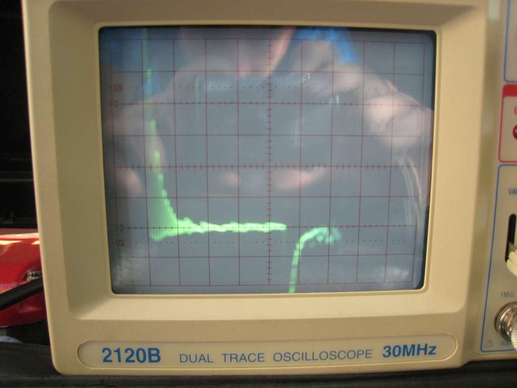
Right now the dwell is at 2.3 ms (as you can see, 0.5 ms/div, 4.6 divisions).
I'll probably cut it to around 1.2 ms, at that point, the coil basically sees the full DC voltage, after 1.2 ms, the electrical energy just goes towards heating the coil and module. (well, technically, it's asymptotic, but for practical purposes)
However, this is at idle, under high load conditions, more dwell may be required, so I'll see how it performs then...

I'm using white heat sink compound from the local electronic surplus store.

After I fix these things, I'll get a brand new module, once it overheats, I guess there's irreversible damage to the semiconductor.
IP: Logged
Dodgerunner
Member
Posts: 9687
From: Lincoln, Nebraska
Registered: Sep 2004


Feedback score:    (61)
Leave feedback


Total ratings: 323
Rate this member

Report this Post09-02-2009 11:55 PM Click Here to See the Profile for DodgerunnerClick Here to visit Dodgerunner's HomePageSend a Private Message to DodgerunnerDirect Link to This Post
 
quote
Originally posted by pmbrunelle:

The wiring you suggested though won't do anything, but great idea, I wouldn't have thought of that on my own. The diode must be connected with its cathode to the positive primary terminal., and the anode to the negative primary terminal. It will be spliced into the mini-harness between the coil and module, not affecting any other wiring.

.


You are correct sir!.. That is what I get for not looking at the schemo and just tossing out an idea, but you knew exactly where I was going with it... Good man.... I think we use to call them anti kick back diodes (relay coils) instead of flyback as used in TVs.

[This message has been edited by Dodgerunner (edited 09-02-2009).]

IP: Logged
pmbrunelle
Member
Posts: 4619
From: Grand-Mère, Québec
Registered: Sep 2008


Feedback score: N/A
Leave feedback


Total ratings: 63
Rate this member

Report this Post09-04-2009 01:04 PM Click Here to See the Profile for pmbrunelleSend a Private Message to pmbrunelleDirect Link to This Post
 
quote
Originally posted by Dodgerunner:


You are correct sir!.. That is what I get for not looking at the schemo and just tossing out an idea, but you knew exactly where I was going with it... Good man.... I think we use to call them anti kick back diodes (relay coils) instead of flyback as used in TVs.


I just thought about this...it doesn't really make sense actually. Rather than dissipate the magnetic field's energy into the secondary, it would just go through the diode, which is counterproductive.

I guess a good module with avalanche rated switching transistor should be ok.

I noticed have like 0.3V of ripple on my power supply, looks like my alternator rectifier cooked. (My trunk fan wasn't operational, I have since repaired that). I think the **** power supply full of harmonics may have damaged the module...
I'll replace the module AFTER I get a new alternator, because I don't want to ruin the new one!
IP: Logged


All times are ET (US)

T H I S   I S   A N   A R C H I V E D   T O P I C
  

Contact Us | Back To Main Page

Advertizing on PFF | Fiero Parts Vendors
PFF Merchandise | Fiero Gallery
Real-Time Chat | Fiero Related Auctions on eBay


Copyright (c) 1999, C. Pennock