I have been working on a flow bench. Since its starting to develop, I figured I would give it a seperate thread, rather than crowding my other one.
Anyhow,
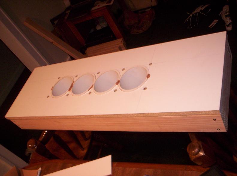
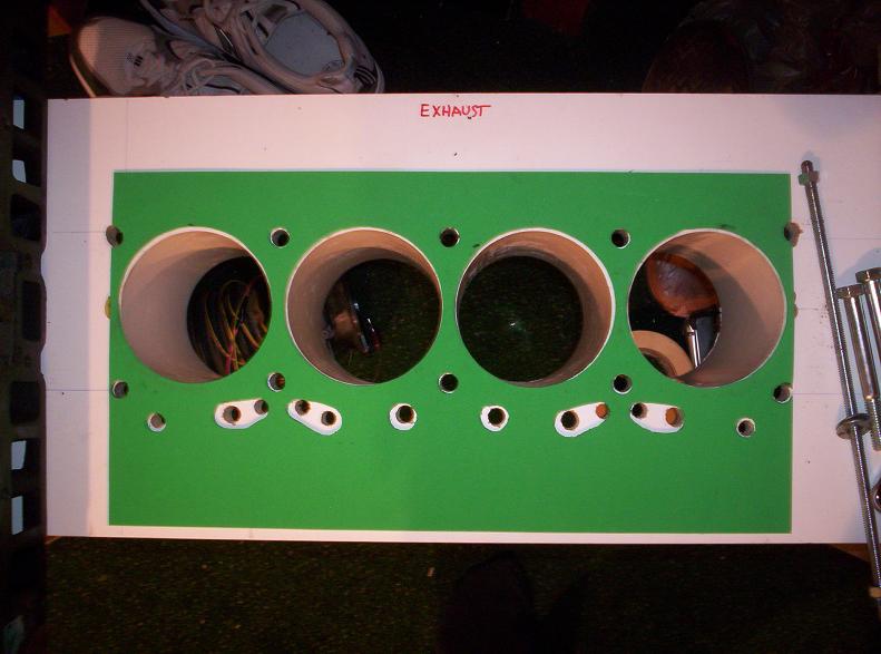
First I made a plate from a piece of cheap melamine that had bolt holes and bore centers in the correct places. While I suppose this is possible using a set of transfer punches and a good guess at the location of the bores, I sketched out the bolt and bore layout from a Super Duty head machining print. Also, since I'm using PVC inserts to seal against the bottom of the head, I had to cut the holes bigger than 4".
Schedule 40 PVC has a nice 4" ID that is a good approximation of the 2.5 bore, but the OD is about 4.52" Since the bore centers are only 4.40" inches on a Duke, this meant that the holes in my plate overlapped.
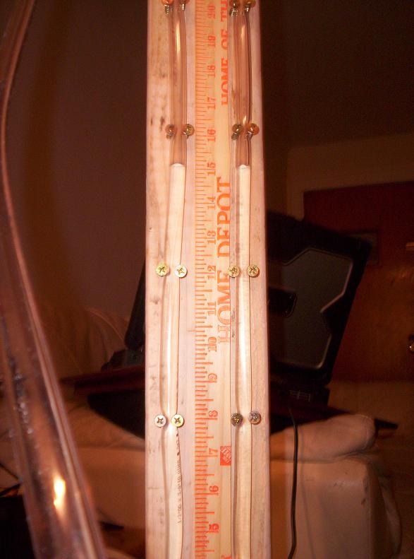
The next problem the bore center vs PVC thickness issue was related to making the PVC fit so close together. To do this, I had to machine about .050" off the OD of the pipe in two diametrically opposed places down the full length of the pipe- about 6 inches. Here's a crappy pic attempting to demonstrate that the pipe had "flats" down the sides when I was done.
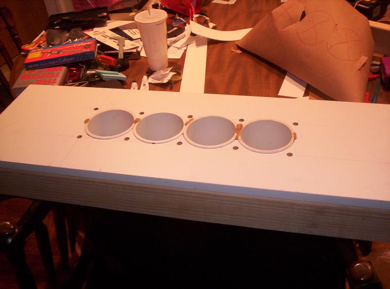
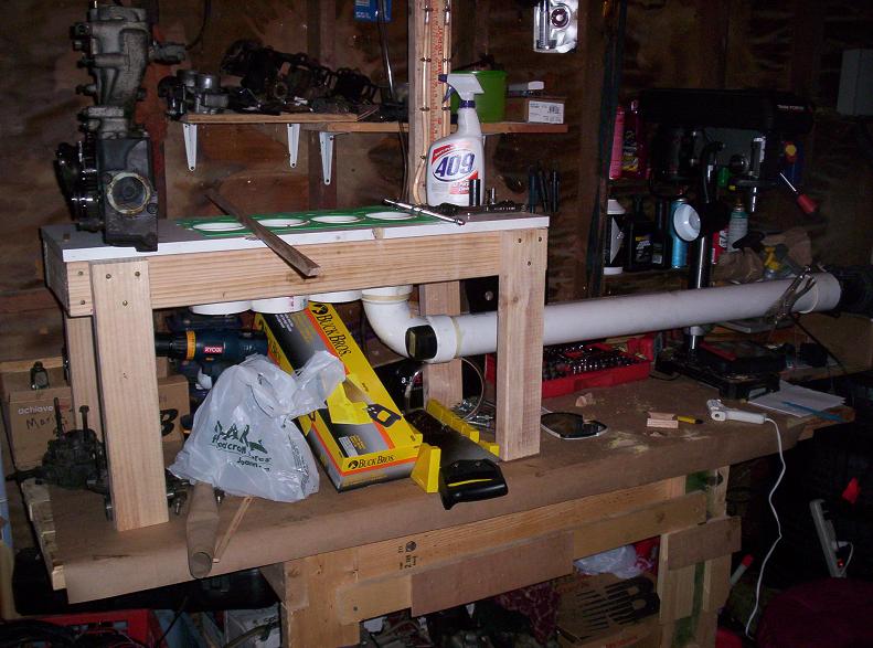
After getting the pipes to fit, I simply turned the whole thing upside down, put 2mm spacers around the perimeter of the melamine, and pushed the tubes through and epoxied them. The 2mm spacers ensure that the PVC pipes protrude from the head mounting face more so when I put the head on, clamp force is concentrated around the bores. Heres some pics of the nearly-final product:
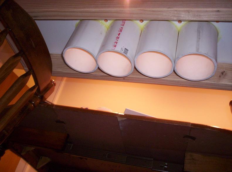
And a shot from underneath:
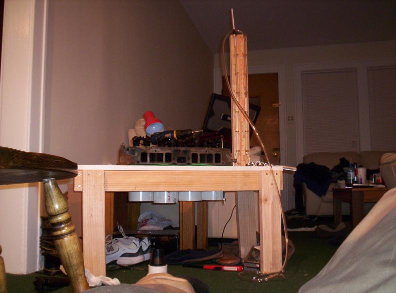
Here it is on legs:
Here's the gasket I hand-cut with an X-acto knife and about 15 minutes of concentration:
Manometer for measuring pressure drop **1/8th inch water precision is good enough for me, for now, improvements on the way...**
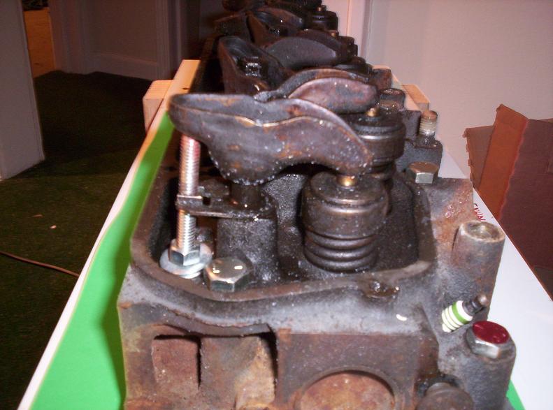
Valve actuation detail (ball tip ground onto 5/16-18 threaded rod) This pic is at .500" valve lift: Note the threaded rod passes all the way through the head, through the melamine board, and is double-nutted at the end so I have an easy way to turn it.
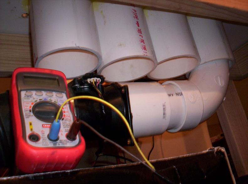
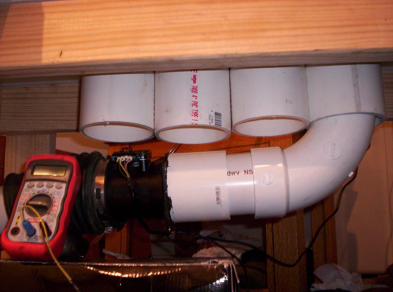
The whole deal almost ready to go:
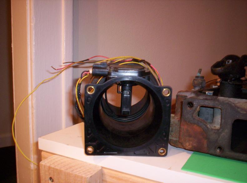
The ghetto 1990's Ford 0-5V MAF my friend gave me, that'll be going in line as soon as I can verify its calibration:
[This message has been edited by KurtAKX (edited 04-14-2009).]
check this site out they sell a flow bench thing that works with a vacume cleaner i think it is about $500 at least thats what it was about a year ago http://www.audietech.com/flow-quik/what-it-is.html
[This message has been edited by engine man (edited 04-15-2009).]
Add some plastic pistions and you almost have an engine.. Very Interesting, good job..!
Not quite single; engaged but we're stuck in jobs and homes 2.5 hours apart. This will probably make its way back out to the garage or basement before she shows up
IP: Logged
05:33 PM
darkhorizon Member
Posts: 12279 From: Flint Michigan Registered: Jan 2006
In reality its to measure how disappointing spending 3 years building a duke will be when it is actually done.
In reality, I guess it was just another thread for you to post more pointless derision in. If you had been paying any attention to what he was doing, you would know it has nothing to do with disappointment.
[This message has been edited by carbon (edited 04-15-2009).]
IP: Logged
08:47 PM
DPWood Member
Posts: 540 From: Aylmer, Ont. Canada Registered: May 2002
In reality, I guess it was just another thread for you to post more pointless derision in. If you had been paying any attention to what he was doing, you would know it has nothing to do with disappointment.
sorry, this time it is really an inside joke between Kurt and I.
I shoulda said "will it flow 4.9 heads?"... woulda been one of the more friendly inside jokes.
How does it work? I"m guessing something will mount to those tubes you have sticking down?
You'd be right. Here's what goes in the bottom. Its an ancient 90s Ford 0-5V MAF. I did some testing tonight; I need to add a laminar flow element to my down-pipe.
IP: Logged
12:25 AM
KurtAKX Member
Posts: 4008 From: West Bloomfield, MI Registered: Feb 2002
In reality, I guess it was just another thread for you to post more pointless derision in. If you had been paying any attention to what he was doing, you would know it has nothing to do with disappointment.
Its ok. I can't even hear him unless I'm looking for parts in his backyard. Besides, he's just jealous that he couldn't figure out how to get his iron duke to run right and ended up giving it to me.
We'll see the reaction when I match his hp/liter without the blower.
IP: Logged
12:38 AM
v8fiero400 Member
Posts: 963 From: Houston,TX,USA Registered: Jan 2004
Looking good.... will be interested to see what numbers you will get.
My thoughts are that you will actually find that the early heads flow as much or even more CFM than the newer heads.
The redesign on the newer heads and intake is based on more efficient (not larger) ports....improved intake velocity and swirl into the cylinder and better scavenging of the exhaust... The newer engines have longer and more equal length intake runners which gives them more torque and horsepower in the rpm range that they are designed to operate in. GM did not design the newer heads to flow better at high rpm. In fact the ports in the newest duke engines (90-93) are actually the smallest of all the years on the exhaust side........yet they make more power all the way to the red line!!!... because the efficient D shaped exhaust ports scavenge better with less reversion when the valve starts to close. The early dukes have relatively big ports despite the very conservative cam timing and poor flowing early TBI's .... all this does is kill torque.
[This message has been edited by v8fiero400 (edited 04-16-2009).]
IP: Logged
01:40 AM
KurtAKX Member
Posts: 4008 From: West Bloomfield, MI Registered: Feb 2002
Looking good.... will be interested to see what numbers you will get.
My thoughts are that you will actually find that the early heads flow as much or even more CFM than the newer heads.
The redesign on the newer heads and intake is based on more efficient (not larger) ports....improved intake velocity and swirl into the cylinder and better scavenging of the exhaust... The newer engines have longer and more equal length intake runners which gives them more torque and horsepower in the rpm range that they are designed to operate in. GM did not design the newer heads to flow better at high rpm. In fact the ports in the newest duke engines (90-93) are actually the smallest of all the years on the exhaust side........yet they make more power all the way to the red line!!!... because the efficient D shaped exhaust ports scavenge better with less reversion when the valve starts to close. The early dukes have relatively big ports despite the very conservative cam timing and poor flowing early TBI's .... all this does is kill torque.
I'd be willing to bet that the newer heads do in fact flow more. In fact, I'd be willing to bet a 12 pack that the newer heads flow more (especially on the intake)
Two things: 1) You're saying the early heads have relatively big ports. Relative to a SBC or SBF of the same displacement, the intake ports are actually pretty small. The last 2.5 inches of the port (relative to the centerline of the intake valve) is smaller in cross-section than even the wimpiest 'peanut port' smog or TBI 305 heads. You can't even see most of the intake valve. The exhaust side of 2.5 heads has always been relatively healthy, and especially so considering that the amount of exhaust flow needed is proportional to the effectiveness of the intake side (not very good intake in this case)
2) The thing about the newer heads having smaller ports isn't entirely true. While the intake ports are not as tall in 87+ heads, they are both wider, and come in from higher up, adapting a small piece of the 801 SuperDuty head mentality. High ports increase the efficiency of the port, by making the 90 degree turn air must make into a more gradual bend. Late exhaust ports are smaller, but the areas that are 'closed in' relative to the earlier heads (bottom edges of the port) don't contribute much (if anything) to the port flow. The idea is to eliminate areas where there is 'lazy air', both on the intake and exhaust. Slow moving air isn't using its inertia to ram itself into the cylinder, nor is it using its inertia to scavenge the cylinder.
At any rate, I agree with you about the cam specs being pretty conservative.
[This message has been edited by KurtAKX (edited 04-16-2009).]
IP: Logged
11:58 PM
Apr 17th, 2009
KurtAKX Member
Posts: 4008 From: West Bloomfield, MI Registered: Feb 2002
I'd be willing to bet that the newer heads do in fact flow more. In fact, I'd be willing to bet a 12 pack that the newer heads flow more (especially on the intake)
Two things: 1) You're saying the early heads have relatively big ports. Relative to a SBC or SBF of the same displacement, the intake ports are actually pretty small. The last 2.5 inches of the port (relative to the centerline of the intake valve) is smaller in cross-section than even the wimpiest 'peanut port' smog or TBI 305 heads. You can't even see most of the intake valve. The exhaust side of 2.5 heads has always been relatively healthy, and especially so considering that the amount of exhaust flow needed is proportional to the effectiveness of the intake side (not very good intake in this case)
2) The thing about the newer heads having smaller ports isn't entirely true. While the intake ports are not as tall in 87+ heads, they are both wider, and come in from higher up, adapting a small piece of the 801 SuperDuty head mentality. High ports increase the efficiency of the port, by making the 90 degree turn air must make into a more gradual bend. Late exhaust ports are smaller, but the areas that are 'closed in' relative to the earlier heads (bottom edges of the port) don't contribute much (if anything) to the port flow. The idea is to eliminate areas where there is 'lazy air', both on the intake and exhaust. Slow moving air isn't using its inertia to ram itself into the cylinder, nor is it using its inertia to scavenge the cylinder.
At any rate, I agree with you about the cam specs being pretty conservative.
Maybe you are right about 87-88 outflowing 84-86 heads. The runners are raised in the newer heads... and that alone may make them flow better. However I think the newest heads 1990+ .... if you end up testing these on the flow bench.... will probably flow less at least on the intake side.... If you remove the intake valve you will see that intake port is far pushed over to one side of the stem and there is sort of a ramp that will create a swirl when the intake valve opens and air enters the cylinder.... it is hard to explain the shape... and I can't find a picture of this newer duke head with the valves removed. These type of heads produce better mid range torque... but will not flow any better after 4500 rpm.... which is OK with a duke since you can't rev them much higher that this anyway.
Anyhow keep up the good work and keep us informed
IP: Logged
12:51 AM
v8fiero400 Member
Posts: 963 From: Houston,TX,USA Registered: Jan 2004
Ok.... I found an example of "swirl port heads".... not a duke head but the port on this chevy TBI head is very similar to the 1990 and newer duke heads....
IP: Logged
12:55 AM
PFF
System Bot
v8fiero400 Member
Posts: 963 From: Houston,TX,USA Registered: Jan 2004
I have not been on this forum for sometime now, my Fiero has been parked for more than a few years due to lack of $$$'s and motivation. Instead I've been playing with flowbenches. Good to see some discussion on an old "love" of mine, maybe this will get me motivated again . . . .
IP: Logged
04:33 PM
Apr 28th, 2009
KurtAKX Member
Posts: 4008 From: West Bloomfield, MI Registered: Feb 2002
OK, so I finally did some proper testing of old style heads to new-style heads. This time I ran some radiused inlets instead of an intake manifold.
I'm not quite sure why the late head graph has the dip at .400; I guess it could be either a reading error or some weird unstable transition from a swirl-type flow to tumble flow. I suspect this because the late head doesn't have the same kind of severe ramp in the intake bowl.
[This message has been edited by KurtAKX (edited 04-28-2009).]
IP: Logged
12:31 AM
KurtAKX Member
Posts: 4008 From: West Bloomfield, MI Registered: Feb 2002
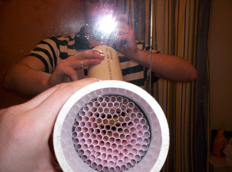
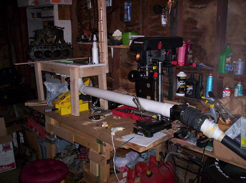
Here's a cluttered-a$$ shot of the corner of my shop dedicated to the flow bench I have the laminar flow element and MAF more than 10 diameters downstream of the elbow; my reasons for doing that involve the added stability of a fully-developed velocity profile- A topic better for Will to explain than me.
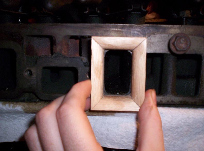
So about those radiused inlets: I have found the following to be common practice: 1) Clay is commonly used to make a smooth inlet radius, especially for uncommon engines 2) A common standard Inlet radius to the port is .500"
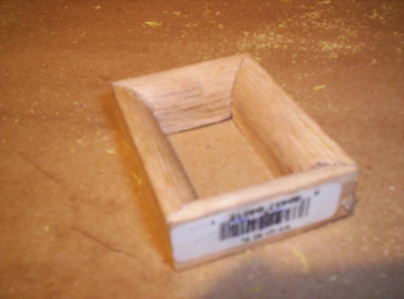
Knowing those two things I set out to make a proper inlet to the port so I wouldn't have to bolt on an intake manifold every time (though I will sometimes) and so my numbers are comparable to "industry standard" I wanted something more consistent than a clay shape which could change day-to-day. After thinking about how to make a consistent radius, I went to Home Depot $2.60 worth of 1/2" quarter round trim and a $7.99 miter box and saw set, I had the following:
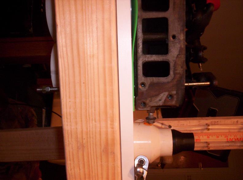
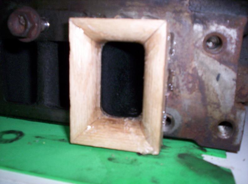
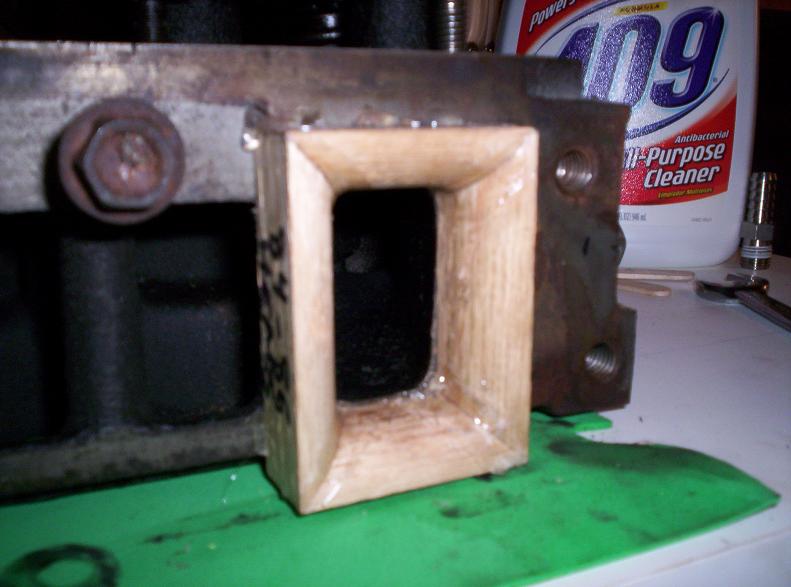
Here's the fit to the head; I later blended any edges with hot glue.
They hot-glue to the head, which holds fast during testing, but pops loose afterward.
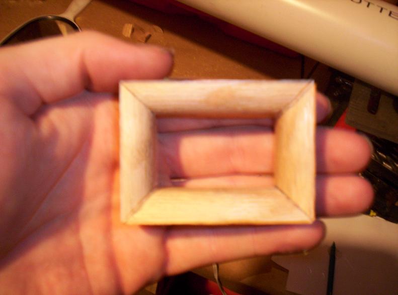
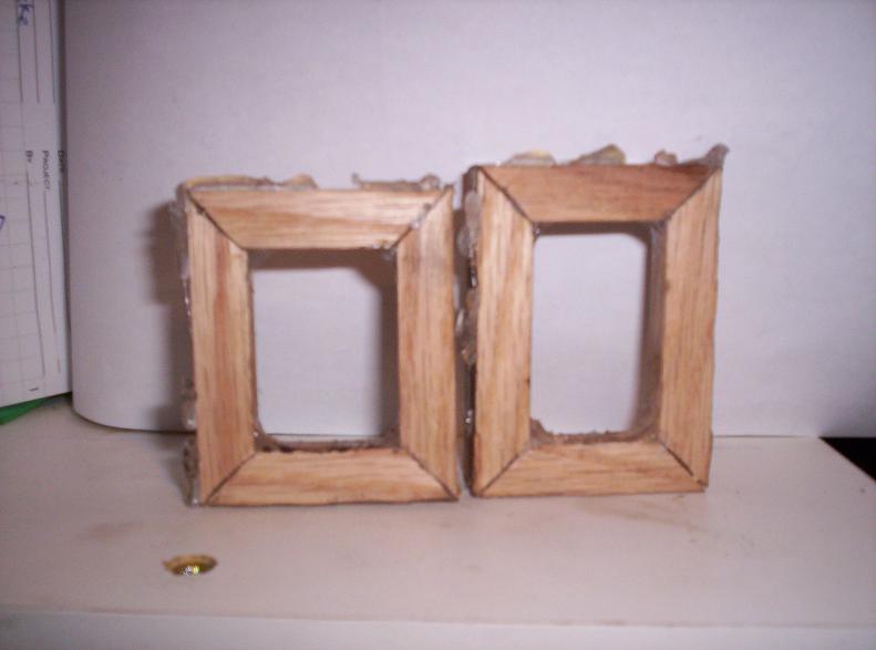
Here's a comparison of the early to late head pieces: Late ports are not as tall, and are slightly wider.
[This message has been edited by KurtAKX (edited 04-28-2009).]
IP: Logged
01:28 AM
MJ Member
Posts: 214 From: Punxsutawney Registered: Jun 2008
Nice work. We build kart racing engines here and have a pretty dedicated shop for doing so. We have a homemade flowbench that will flow carburators and carb/block together. It works very well and is somewhat similar to your set-up but more refined. I'll have to post you a pic when I get a chance.
IP: Logged
03:01 AM
PerKr Member
Posts: 641 From: Mariestad, Sweden Registered: Nov 2006
I'm curious as to how you calibrated your MAF on your bench?
There has been alot of discussion on my flowbench forum about using a MAF in a flowbench application and it was not recommended. I personally have never messed around with one other than to play with it on my small engine dyno as a way of testing the inlet airflow on a tested engine. If you have the laminar element right in front of your MAF you are going to be directing a stream of airflow directly at your pickup which "could" induce higher reading. Your laminar flow element should be upstream of your sensor. I found in pitot bench design that the laminar element had little if any effect on an averaging pitot. Would be interesting to see what it does on a MAF? I have since converted all my thinking over to orifice plate style flowbench design which is not effected by temp and baro if the motors are after the plate.
The sharp edge outside of your inlet radius box is going to effect how the port "sees" your airflow. I would break that edge, Ideally I would extend the edge out from the radius so you have a flat surface leading up to the radius. The air comes in from the sides of the port and needs a flat surface around the inlet. Most shops I know cut a hole for the port and then use a router to make their radius on a flat piece of plastic or wood. Clay as you stated is not a good way of doing this as you can't get the same shape from test to test. Testing with the intake installed would be the preferred way as the intake will have an effect on total flow.
Don't take my questions wrong . . . I'm all for DIY and applaud anyone who builds their own flowbench!
I have an 84 with a 2.5 sitting out back that is pretty much toast and haven't gotten motivated to work on it in many years. Might just spark me to play with it again . . .
[This message has been edited by Brucepts (edited 04-28-2009).]
IP: Logged
05:05 PM
PFF
System Bot
Apr 29th, 2009
KurtAKX Member
Posts: 4008 From: West Bloomfield, MI Registered: Feb 2002
I'm curious as to how you calibrated your MAF on your bench?
There has been alot of discussion on my flowbench forum about using a MAF in a flowbench application and it was not recommended. I personally have never messed around with one other than to play with it on my small engine dyno as a way of testing the inlet airflow on a tested engine. If you have the laminar element right in front of your MAF you are going to be directing a stream of airflow directly at your pickup which "could" induce higher reading. Your laminar flow element should be upstream of your sensor. I found in pitot bench design that the laminar element had little if any effect on an averaging pitot. Would be interesting to see what it does on a MAF? I have since converted all my thinking over to orifice plate style flowbench design which is not effected by temp and baro if the motors are after the plate.
The sharp edge outside of your inlet radius box is going to effect how the port "sees" your airflow. I would break that edge, Ideally I would extend the edge out from the radius so you have a flat surface leading up to the radius. The air comes in from the sides of the port and needs a flat surface around the inlet. Most shops I know cut a hole for the port and then use a router to make their radius on a flat piece of plastic or wood. Clay as you stated is not a good way of doing this as you can't get the same shape from test to test. Testing with the intake installed would be the preferred way as the intake will have an effect on total flow.
Don't take my questions wrong . . . I'm all for DIY and applaud anyone who builds their own flowbench!
I have an 84 with a 2.5 sitting out back that is pretty much toast and haven't gotten motivated to work on it in many years. Might just spark me to play with it again . . .
Well, I started from a set of sharp-edged orifices from .375" to 2" and a known air density (a function of altitude and termperature).
I ran the delta P across the orifice at the same time I was drawing through the MAF. What this gave me was a set of points (volumetric flow vs. voltage for those environmental conditions).
I put those points into a spreadsheet, fit a function (a 3rd order polynomial in this case, R value of .999) and pulled out a MAF calibration curve.
I put this function in the spreadsheet. When I flow a port instead of an orifice, I get a voltage from the MAF and a delta P in inches of water. I input voltage to the spreadsheet and it spits out a CFM (for the given pressure drop).
I then use the Bernoulli-derived equation: Flow (@ new rate) = orig flow rate x sqrt (new delta P/ old delta P)
Using a MAF is tricky though, for two reasons: 1) you have to be careful how you bring air to the inlet of the MAF. If there is a turbulence inducing element such as an elbow or valve upstream of it, you have to have at least 10 times the diameter and/or a laminar flow element in place to return the flow's radial velocity gradient to "normal" so you get consistent readings. 2) MAFs measure mass, not volume. This means that when there is a significant temperature change, you have to apply an air density correction factor. I have created a table of air densities for given temperatures between 50 and 100F. Alternatively, you could run a quick recalibration with an orifice plate and create a new volts-to-cfm function.
[This message has been edited by KurtAKX (edited 04-29-2009).]
Update: I left a stock '655 head at work. I didn't memorize flow at all the lifts, but I do remember that @.500" lift, result was: my flow bench: 139 cfm work's flow bench 140 cfm
I think I'm closing in on the accuracy...
IP: Logged
11:10 PM
May 6th, 2009
PerKr Member
Posts: 641 From: Mariestad, Sweden Registered: Nov 2006
Must get progress my 88 Duke needs a Rebuild and i Wanna know if the new heads are the way to go from the balzer or should i stick with the head its got
IP: Logged
04:40 AM
May 7th, 2009
KurtAKX Member
Posts: 4008 From: West Bloomfield, MI Registered: Feb 2002
I've done some head porting, but like J. Callies and Vanderley engineering found out, there's no easy porting "magic bullet" to get major power out of the stock heads. I've not been able to get the ported version of the early head to outperform the stock 87+ head.
Still working on it.....
IP: Logged
12:55 AM
Jun 13th, 2009
PerKr Member
Posts: 641 From: Mariestad, Sweden Registered: Nov 2006