Referencing the Fiero AC control head unit, does anyone know the specs for the two (2) thermistors?
Mike, I did the original analysis of the climate control but I never determined the specific parameters for those PTC overcurrent protectors. Other than the max operating voltage (which is like 16V) I believe the only things you need to know are the "normal" and "abnormal" (stalled) currents to the actuators.
One you have measured those two parameters, just pick one with a trip current higher than the normal current but lower than the stalled current.
I don't know if these are the guys that made the original devices, but there's a good explanation on their site and some good charts as well. >> http://www.rtie.com/ptc/overcurrent.htm
I betcha Digi-Key has something that would work... You don't care about the form factor, right?
Bruce at FTF
IP: Logged
10:29 AM
Cajun Member
Posts: 1616 From: Youngsville, La., USA Registered: Dec 2003
I have given up hope of finding a suitable PTC. Instead, had my son pickup a control unit out of a crashed Fiero at a local salvage yard. The plan is to pull the PTC's from the control unit and use them. I have a higher level of confidence with those PTC's then trying to get the correct ones else where.
Again, thanks for the feedback.
Mike
IP: Logged
08:42 PM
Daniel Member
Posts: 282 From: Calgary, Alberta, Canada Registered: Jun 2003
Cajun I have no problem with you forwarding your wiring diagrams to me, I tried to respond with an attatchement. Sometimes spam filters just filter out all telus emails.
I ended up having a long day at work and will try to show what I did to the ac bracket for more clearance in the next couple days.
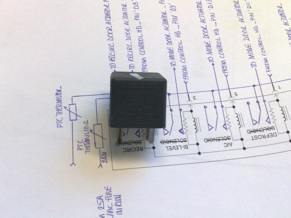
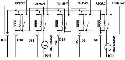
My relay logic is listed below, just missing the protection diodes to reduce the power spikes from the relays closing. I may have had to change the order, I used this method to ensure only 1 mode could be triggered at a time. I believe I made some changes in order, however I am unsure as to weather I made this diagram before or after thoser changes. For me it was relatively easy to change as I used built small jumpers that had enough movement to allow the changes
The mode button just scrolls through the different air curculation modes, except defrost (seperate button) and recirc(can use with all modes but I believe defrost) In auto mode you can use recirc, but the mode is decided by the conroller, and can change while driving, not as noticable in the grand prix.
Still havent done much with the a/c clutch controller
IP: Logged
08:53 PM
May 27th, 2009
Cajun Member
Posts: 1616 From: Youngsville, La., USA Registered: Dec 2003
Thanks for the feedback. Your relay logic is pretty much the same as mine. Including the installation of the thermistors. Also, thanks for the additional information concerning C16 & D4. I had noticed in your original post. That specific information is missing from the wiring information I had collected.
Hopefully, I have correctly sorted out the AC request signal and compressor signals.
When I get back to the plant tomorrow, where I have a better internet connection I will forward to you my work. For ease of sending I had my TA convert all the drawings and wiring diagrams to PDF format.
Yes, I'm very interested in your installation of the Blow Motor resistor module.
Again, thanks for your assistance.
Mike
IP: Logged
10:59 AM
May 28th, 2009
Daniel Member
Posts: 282 From: Calgary, Alberta, Canada Registered: Jun 2003
Cajun The wiring diagrams appear good, I have emailed you in more detail, if you havent gotten the reply please email me or post here, I believe the a/c trigger for the relay puts out a voltage, not a ground so it's wiring may need some work, I am still in the process of figuring it out. (currently have a seperate switch for the a/c and rad fan)
I will try to get better info of the mod for the heater blower controller over the weekend, have been busy at work, if not here is the jist of it:
- mount the controller as low as possible, leaving the lower oem bolt hole from the resistor pack - - if mounting with a metal backer use the lower oem bolt hole from resistor pack and mount it under the a/c bracket, using the a/c brackets bolts as support. - mount as close to passangers side - you should see a seam / bend, get close to this - adjust the a/c bracket to fit overtop of the motor controller, trim and bend the bracket slightly - not sure if bracket is required, I trimmed, and bent it while trying to keep as much support as possible for the a/c component up front. I also installed a spacer to keep the bolt from sticking to far through the strap for extra clearance.
IP: Logged
09:16 PM
May 29th, 2009
FTF Engineering Member
Posts: 710 From: Near Philadelphia PA Registered: Sep 2001
Glad to help. Sorry I couldn't do more for you on those PTCs. On the bright side, however, you can be sure that the ones you'll harvest from that donor are suitable for use.
About the signal for the A/C... The original Fiero system used positive logic for the A/C control. Looking back, I didn't specify in my original list, but here's a more specific description.
Change: G - A/C on signal to ECM To:G - A/C request signal to ECM. Hot to request A/C.
And while I'm there, one more
Change: K - Engine cooling fan relay enable To:K - Engine cooling fan relay enable. Ground to turn engine cooling fan on.
Other thoughts?
1) You never want to run the A/C compressor without the interior fan running because it can damage the compressor if you do that. The original Fiero system never had to worry about that because the interior fan always ran except when the OFF button was pressed. I don't know if you're new controls have an "OFF" setting for the interior fan speed, but if it does, you need to insure that it interlocks with the A/C compressor so it cuts off the compressor if you shut off the interior fan.
2) I don't know if the Fiero compressor can handle rapid on-off cycling. Some compressors are more accepting of that and others don't like it at all and can be damaged if you do that. Again, I don't know if your new controls have the ability to jackhammer the A/C compressor "on-off-on-off", but you don't want to do that. The original Fiero controls didn't have any specific provisions to prevent this, but the nature of the push-buttons made if unlikely. If you're using rotary controls, you need to think about what the connections are going to do BETWEEN positions. If you're running the A/C an then move the knob to a different position, even another A/C position, do all the signals go no-connect between positions? You don't want that.
3) A small detail, but...
quote
My relay logic is listed below, just missing the protection diodes to reduce the power spikes from the relays closing.
The spikes are from the relays opening, not closing. "De-energizing" to me more accurate. You'll get a spike when you de-energize the relay coil. I'm pretty sure you already knew this, but just in case...
Anything else I might be able to do to help, please let me know.
Bruce
IP: Logged
09:48 PM
May 30th, 2009
Daniel Member
Posts: 282 From: Calgary, Alberta, Canada Registered: Jun 2003
I was tired and had a few long days of work this week, and didn't want to research what the diodes were protecting against, However I did do lots of research at the time to get them mounted correctly. Yes the diodes reduce the spike of de-enerdgizing the relays.
For the rad fan wiring, however in you'r diagram it shows: H - GND for engine cooling fan relay K - Engine cooling fan relay enable This was fairly clear to me, touch these wires together for rad fan, therefore rad fan requires a ground to operate
I have found out that K - Engine cooling fan relay enable requires a 12v input. I will need to do some test to see how the system operates from the grand prix, probabaly set up some sort of test light just to see it's operation. In the grand prix the A/C control signal goes to the ecm as I am unsure as to if the ecm would be doing the short cycling, or if it is the controller, I will need to look into this further.
Bruce your wiring schematic was very helpful in the setup as most wiring diagrams that I found were missing one or two wires, and were not oriented in the proper line, So thanks for the assistance.
This system still uses buttons, the rotary controlls are just for temperature controll. the a/c light will stay on above 3 degrees celcius in all modes but defrost if a/c is requested (still get a/c in defrost to reduce humidity, just no rad fan) the main problem is adjusting the mode manually you have to push the mode button until the selected air distribution lights up, however in auto mode it will adjust this for you, max heat or max cold in auto mode will give you max cabin blower speed only. When cold and auto mode is selected the blower will start off slow for a while until it has let the coolant heat up some, then go to a higher speed to warm up the cabin.
IP: Logged
10:09 AM
Cajun Member
Posts: 1616 From: Youngsville, La., USA Registered: Dec 2003
Thanks for your help and input. I'm pretty confident that my wiring diagrams will work. I did catch the one error concerning the "K" terminal. All that remains now if for me to begin the acutal build once I return to the states.
Not to worry, I will photograph the build and will post alone with any other notes of the build to assist others if they wish to attempt the build .
One additional question Daniel, where did you install your relay pack? I cannot recall if you ever indicated where it relay pack was installed.
Again, thanks guys.
Mike
IP: Logged
08:00 PM
May 31st, 2009
Daniel Member
Posts: 282 From: Calgary, Alberta, Canada Registered: Jun 2003
I installed the relay pack loosely behind the radio, on the drivers side above the center column accessible from the drivers passanger compartment. I will get a pic by the end of the day. I had not posted where it was yet as I wanted to test it for a while as it is just sitting there loosley, but seems to hold in place fine. I mounted it here for access although it may fit under the passanger speaker ( wiring issues ) or on top of the gas tank in the centre column (very difficult to access).
The spikes are from the relays opening, not closing. "De-energizing" to me more accurate. You'll get a spike when you de-energize the relay coil. I'm pretty sure you already knew this, but just in case...
Anything else I might be able to do to help, please let me know.
Bruce
You get a VOLTAGE spike when you de-energize the coil. but you get a CURRENT spike when you energize the coil. so you do get spikes on both open and close. if the circuit is not designed for the inrush current when you activate the relay you can cause problems. I lost a lot of time troubleshooting systems where the logic was not designed to take the current spikes. Basically if the controller was controlling relays to begin with, it's fine. if it was turning on and off logic you need to make sure that you are not running really close to the current capacity or the current spikes will kill the control circuitry.
IP: Logged
03:32 PM
Daniel Member
Posts: 282 From: Calgary, Alberta, Canada Registered: Jun 2003
I believe it is built to operate solenoids, not relays, but a similar circuit, as the oem unit triggered solenoids to open and close vacume lines, so I believe the relays that I am using should operate fine.
I'm back in the states so I can begin work on the build. I also visited the local Pull-A-Part. Hopefully I have gathered all the parts I will need for the build. I was successful in securing a Fiero AC control unit. The intent is to salvage the thermistors and the connector.
Cajun
IP: Logged
06:43 AM
Daniel Member
Posts: 282 From: Calgary, Alberta, Canada Registered: Jun 2003
I pulled the thermistors from my ac unit, but decided to build a connector myself as I wanted to be able to go back to stock, having an oem connector is definatley the way to go.
IP: Logged
08:12 AM
Riceburner98 Member
Posts: 2179 From: Natick, Ma, USA Registered: Apr 2002
Originally posted by Daniel: I pulled the thermistors from my ac unit, but decided to build a connector myself as I wanted to be able to go back to stock, having an oem connector is definatley the way to go.
If anyone ever needs a stock-sized connector, let me know.. I've got a bunch of extra circuit boards with the connector (and solder-holes for attaching your wires) left from my HVAC adventures.. $5 to cover the board and shipping; you can cut off the rest of the board to make it smaller if needed.. r i c e b u r n e r 9 8 (at) g m a i l (dot) c o m - I forget to check my PM's most of the time..
You can see the board edge sticking out of a box...
And what the boards look like assembled... (they would be bare, no parts on them...)
Found a better pic of the bare boards: (got a little carried away when I ordered them.. LOL)
[This message has been edited by Riceburner98 (edited 06-13-2009).]
IP: Logged
11:31 AM
Jun 14th, 2009
FTF Engineering Member
Posts: 710 From: Near Philadelphia PA Registered: Sep 2001
Originally posted by Riceburner98: I've got a bunch of extra circuit boards with the connector (and solder-holes for attaching your wires) left from my HVAC adventures.
Man... That's hardcore. I just used a hacksaw and cut off the connector end of an original circuit board. I scraped the solder resist off and soldered wires to the bare spots. Wished I had known you had these at the time!
You must have had some $$ burning a hole in your pocket!!
Seriously though... Nice work. Did you sell enough to get your NRE back?
FTF E
IP: Logged
09:40 PM
Jun 15th, 2009
Cajun Member
Posts: 1616 From: Youngsville, La., USA Registered: Dec 2003
That is my requirement when I do any modification or build to my Fiero, have the ability to return to stock without much effort. Pretty much build in any design a "Plug & Play" methodology. It is unfortunate but I ended up destroying a Fiero AC control unit for the thermistors and connector.
I have been testing the 2000 Grand Prix Auto Digital control unit. I want to make sure that I fully understand the functionality of the unit before installing. I did notice that the "AC Request" signal is a 12vdc signal as oppose to a ground signal. I had originaly thought the signal was as the others, providing a ground.
The only issue I have now is the temperature door motor from the donor car is not working. Suppose this means yet another trip to the local Pull-A-Part.
Mike
IP: Logged
09:08 PM
Riceburner98 Member
Posts: 2179 From: Natick, Ma, USA Registered: Apr 2002
Originally posted by FTF Engineering: Man... That's hardcore. I just used a hacksaw and cut off the connector end of an original circuit board. I scraped the solder resist off and soldered wires to the bare spots. Wished I had known you had these at the time!
You must have had some $$ burning a hole in your pocket!!
Seriously though... Nice work. Did you sell enough to get your NRE back?
FTF E
LOL Thanks... Haven't quite recovered everything yet... Less because of other people / demand, more because I get myself into too many projects and don't have time to finish all of them properly. I should have ordered 50, but instead got 200 'cause I thought they were going to be the best selling thing since sliced bread. hehe..
IP: Logged
09:19 PM
Jun 18th, 2009
Cajun Member
Posts: 1616 From: Youngsville, La., USA Registered: Dec 2003
Have you gotten your unit to be fully operational yet? I'm still having issues with my install. Specifically, with the B/L selection. It appears that you do not get the signal when you scroll through the different settings for what I would consider a B/L setting.
Thanks, Mike
IP: Logged
07:14 AM
Daniel Member
Posts: 282 From: Calgary, Alberta, Canada Registered: Jun 2003
Dont have the a/c button working yet, but I will have to check the bi-level mode, I believe I have it working. I had to play with the order of the relays to get some of the modes operating correctly, if you have the power jumping through the relays, switch the order untill they all work properly. Have to go to work, will try to check modes tonight.
IP: Logged
08:27 AM
PFF
System Bot
mswenson289 Member
Posts: 195 From: Cleveland, MO. USA Registered: Dec 2007
I found that the bi-level on my controller was actually controlled by the activation of two of the coils at the same time. Again that was for a Bonne but I bet they are very similar. Back to the relay logic, if I remember right I was able to get all modes with the exception of bi-level and defrost at the same time so I defaulted it to bi-level. Mike .
IP: Logged
01:43 PM
Daniel Member
Posts: 282 From: Calgary, Alberta, Canada Registered: Jun 2003
As stated above by: mswenson289 There are two modes being called for at once, set the bi-level to be first in line for the relay switches similar to below:
The order is probabaly wrong, but that was easy enough to fidget with, the diagram was not fixed after the order was fixed. Playing with the order allows all modes to function correctly, except front defog and defrost are the same (dont have the seperation in the fiero). If Irecall corectly I was having issues with the defrost mode overriding others, so it may have been switched to the last in the sequence.
Cajun i would suggest using a voltmeter to confirm weather you are getting a ground for the b/l mode.
IP: Logged
07:51 PM
Jun 19th, 2009
mswenson289 Member
Posts: 195 From: Cleveland, MO. USA Registered: Dec 2007
Guys: I would also be intrested in how you mounted the motor to control the temp door. Did you leave the orginal Fiero cable in place and remote mount it all(motor) or did you mount it down on the "blue thingy" mount? From the Bonne it had a short maybe 8" bar that was used. Also mounting of the tube for monitoring cabin air temp, I have not fully dove into this but thought I would get an idea or two. Mike
IP: Logged
07:45 AM
Jun 20th, 2009
Daniel Member
Posts: 282 From: Calgary, Alberta, Canada Registered: Jun 2003
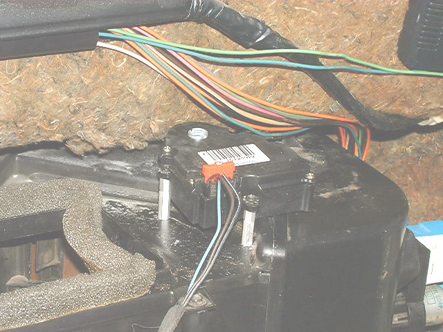
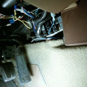
I mounted the temperature motor on top of the air ducts loosley, attached to the stock fiero cable and a custom made arm. I dont have alot of room by the blue dingy thing as I have the performance sound option.
For the cabin air temp sensor I was unable to find its location in the donor car, I used an intake air temp sensor mounted above the passangers footwell, under the map pocket which seems to work well.
IP: Logged
10:14 AM
Jun 21st, 2009
Cajun Member
Posts: 1616 From: Youngsville, La., USA Registered: Dec 2003
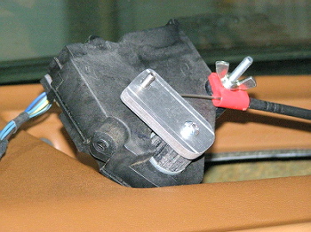
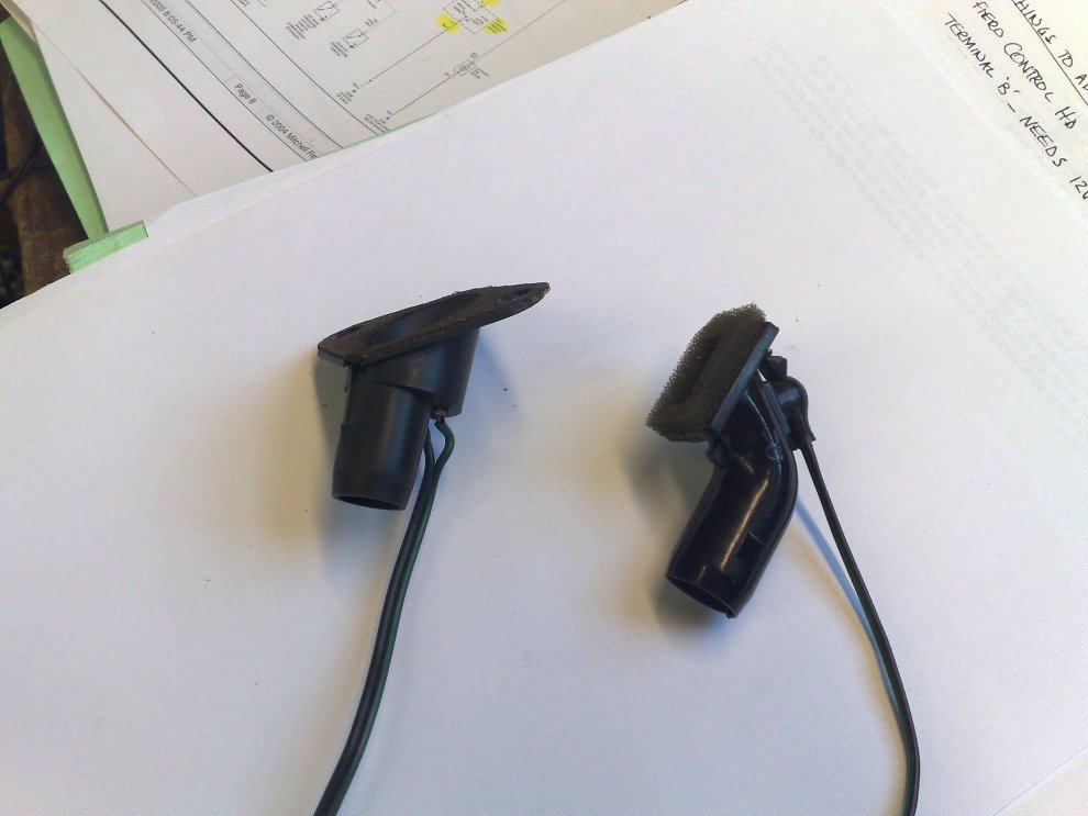
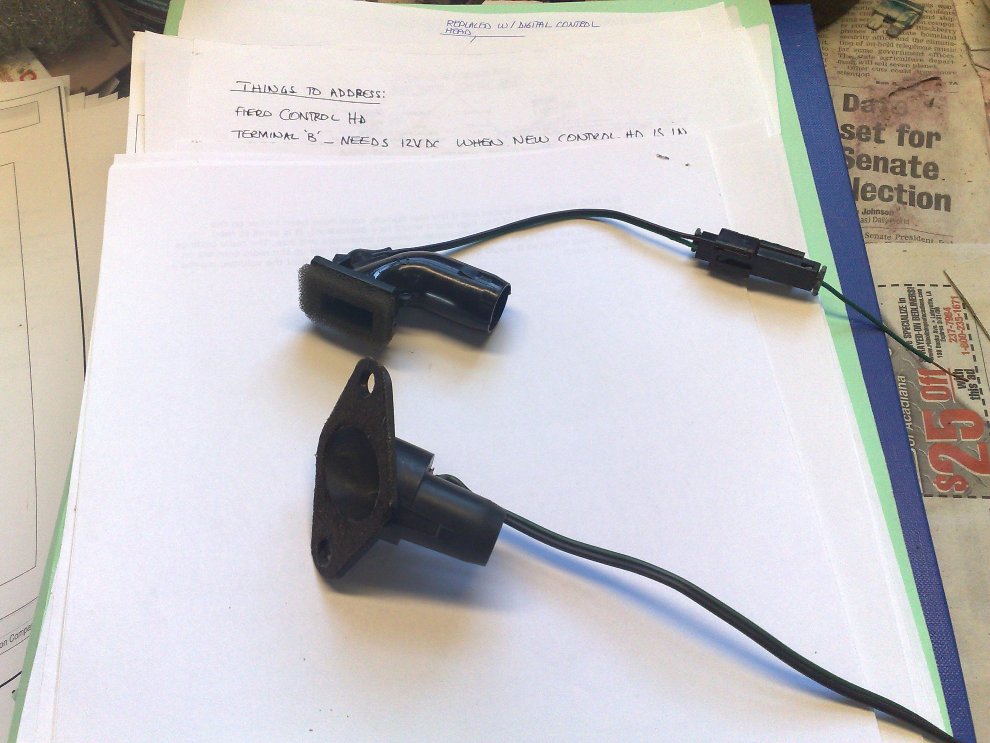
Here are some photos of what I did to install the thermistors for the new system. I have installed the thermistors within a relay case. Pretty much as Daniel did.
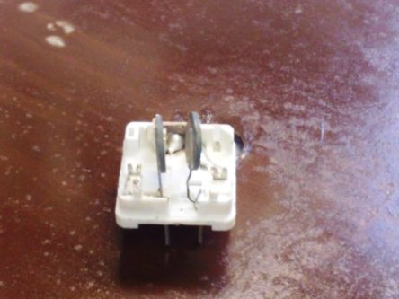
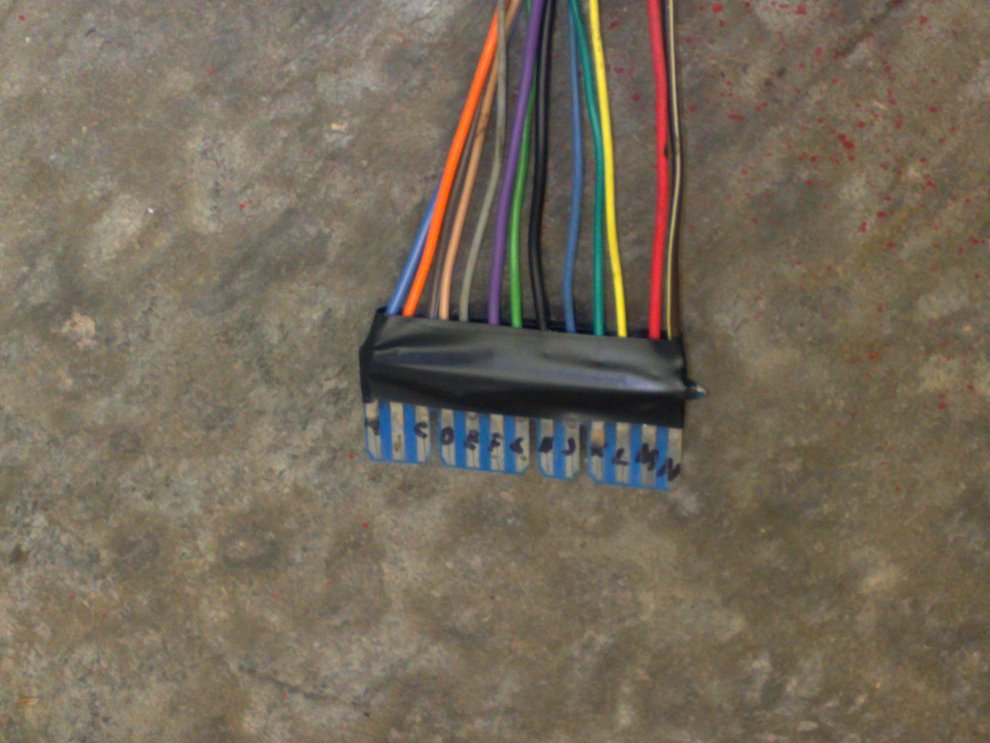
This what the connector looks like. I used the original connector from a Fiero AC control unit, cut off the unneeded section and soldered wires for each connector.
Later today I will take some photos of the relay block that I'm currently rewiring. As Daniel noted concerning relay control I will more than likely have to make another trip to the local Pull-A-Part for another relay block. Not that I need another but I need the connectors for the relay. I have fashioned a tool that allows me to remove the connectors. The relay block that I am rewiring has space for three or four additional relays but lacks the connectors.
Mike
IP: Logged
04:26 PM
Jun 23rd, 2009
Cajun Member
Posts: 1616 From: Youngsville, La., USA Registered: Dec 2003
Mating the adjuster to control the temperature to the the slider on the heater door was not difficult at all, I built the tab so it was near the end of the limits for hot and cold, tested it and built a stop for when the cable went one way (angle was wrong so it was binding without stopping). The motor calibrates itself for full hot and full cold so the arm does not have to be built perfect. The most difficult part I would say was cutting the car to allow for the parts to fit, as well as the wiring.
What meet is on Saturday?
IP: Logged
07:18 PM
Jun 26th, 2009
Cajun Member
Posts: 1616 From: Youngsville, La., USA Registered: Dec 2003
Referencing the temperature motor... what or how did you fabricate a shaft? I see the details of the control arm but have no clue to what you did for the shaft.
Thanks,
Mike
IP: Logged
09:46 PM
Jun 28th, 2009
Daniel Member
Posts: 282 From: Calgary, Alberta, Canada Registered: Jun 2003
The main shaft was made out of a semi soft plastic, UHMW plastic, turned on a mini lathe, and sanded to fit inside the shaft, then the bolt threaded through to tighten it up, The main arm is 3 pieces of 1/16" aluminum, two cut to the d shape of the shaft, the third with just a hole for the bolt to go through, and stuck together with double face tape. This should work without the plastic core, and just a bolt and nut to hold it in. I also added a stop after testing and determining in one of the directions of travel it needed to stop sooner than it did, relatively easy to do for me, it may have been easier for most to leave more room on the cam to allow different positions to be tested, as in one direction it will easily auto-stop is built within it's range of play.
My source for the wiring diagram must have been wrong D9 must be HTR and D10 must be B/L, That must have been why it took me some tinkering to fix my wiring, I thought I had screwed up when it was the wiring diagram that caused me grief.
IP: Logged
12:15 AM
RCR Member
Posts: 4454 From: Shelby Twp Mi Registered: Sep 2002
From RCR in:https://www.fiero.nl/forum/Forum2/HTML/043545-6.html
quote
Originally posted by RCR:
Bob
This would be the best mount method in my opinion, however I was unsure if I had the space, to do so with the dash in place and did not want to hit the heater core with a screw.
IP: Logged
10:05 AM
Jun 29th, 2009
Cajun Member
Posts: 1616 From: Youngsville, La., USA Registered: Dec 2003
I also prefer this mounting method for the temperature controller. As mentioned by Daniel, not sure if the installation can be accomplished with the dash in place and what are the hazards of damaging the heater core in the process.
Mike
IP: Logged
03:25 AM
mswenson289 Member
Posts: 195 From: Cleveland, MO. USA Registered: Dec 2007
Heater core cover comes off that end with little effort. Might take a look and verify clearance By mounting it there on top of the heater core does it effect linkage clearance? I thought with my testing it put the arm to high. Mike
IP: Logged
08:08 AM
Apr 22nd, 2010
1986GTV8 Member
Posts: 1259 From: Orlando,FL,USA Registered: Mar 2002


 I just used a hacksaw and cut off the connector end of an original circuit board. I scraped the solder resist off and soldered wires to the bare spots.
  Wished I had known you had these at the time!