| | | quote | Originally posted by spark1:
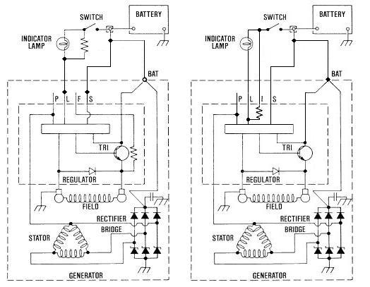
Here is a comparison of the two alternator types; the Fiero is on the right ...
|
|
Just a minute!!! That's not the correct alternator wiring schematic for the '88 Fieros. The CS-130 alternator does
not receive field excitation current through the "L" terminal.
* Most of what follows was originally posted in
this thread. The schematic below was copied directly from the '88 FSM.
The three wires in the harness connector to the alternator (per the 1988 FSM) are used as follows:
S terminal (3mm red wire) -- Voltage sense (based on the wire size, it may also be a backup path for field excitation current)
F/I terminal (0.8mm brown/white wire) -- Ignition switch position sense (hot in run only)
L terminal (0.8mm brown wire) -- "Charge" indicator drive (this is NOT used for field excitation current on the CS-130)
P terminal (no connection) -- "Pulse/phase" output (12 volt square wave, indicates alternator rpm)
.gif)
This still leaves open the question why
Silentassassin185 is seeing voltage present on the "L" terminal of the connector when the ignition switch is off. The only terminal that should have +12 volts on it when the ignition switch is off is the "S" terminal. Is it possible that the sense (red) wire is somehow shorted to the indicator (brown) wire either at the connector or back up in the wiring harness?
* From the '88 FSM:
"When the Ignition Switch is placed in RUN, voltage is supplied to terminals L and F, turning on the Regulator ... The digital regulator controls the Charge Indicator light with a solid state driver. The driver turns on the light whenever undervoltage, overvoltage or a stopped generator is detected."[This message has been edited by Marvin McInnis (edited 09-08-2009).]


 .
. 
