I don't have access to my 86 SE & i am working on an automatic climate control system for it. Can anyone tell me which direction the blend door moves going from hot to cold, CW or CCW, as viewed from above? Also approximately how many degrees does the door move from full hot to full cold? Thanks, Gary
IP: Logged
01:53 PM
PFF
System Bot
Riceburner98 Member
Posts: 2179 From: Natick, Ma, USA Registered: Apr 2002
Since this is pretty much burned into my brain now......... Looking down at the lever, Clockwise is cold, counter clockwise is hot. Cable end that attaches to HVAC controller moves about 1.2" out -> in from full hot to full cold. Lever on top of HVAC box moves almost exactly 60* from full hot to full cold.
Any other questions, feel free to ask. I have an HVAC box sitting behind me... When I mounted a servo directly to the top of my 'box I used a GM P/N 16124922 servo motor, which used to be like $40 new, now they re-manufactured them with all plastic parts (used to be a metal shaft) and surface mount components, and the price went to $320... If I remember right it went full hot -> full cold in 60*. At least I think it did..
If you by any chance want to use an LCD screen, let me know... I had to order 500 of them as a minimum.... I'll be happy if I sell 100 over the next couple years, so I've got some spares. LOL
IP: Logged
06:01 PM
Mar 25th, 2009
AARTD1 Member
Posts: 35 From: St Charles,IL USA Registered: Oct 2005
Thanks a lot for the info, its exactly what I need. I think I'm going to use the blue LED display that I have, but, out of curiosity, what would a LCD display cost? Gary
I think they're a bit big for a "stock" Fiero console.. The panel is about 7 1/4" x 2 1/2". I can't find my console panel at the moment to compare it to..
The entire control system is $500 (tons of labor..), but as for the LCD screens alone, I'd say $5 if you want one. I'll have about 400 spare ones. Thing is you'd need to connect it to an LCD driver chip, then program your microcontroller / microprocessor to drive it.. Then of course backlight it. It's just the "bare" LCD glass with 22 pins. It depends on how deep you're getting into the HVAC controller, if you want to go through all the trouble of getting it working.
I'd tried to use some dot matrix LCD panels when I first started out making these panels, but just couldn't get the graphics to look right. (well, to match the exact graphics of the Diablo anyway) The pixel size was just too big on all that I could find, so I had these made. Each graphic / character is a separate LCD segment, which you control with the driver chip. The screen itself is about 6" x 1". I have some old-revision circuit boards that I probably won't use (slightly different button layout, etc..) but that have the driver chip and LEDs on them for the backlight. They use an "SPI" serial bus that most microcontrollers (even the BASIC Stamp) can write to, you basically just map out all the segments and write to registers in the LCD chip to turn them on and off. You could probably trim off all the excess circuit board and just leave the 6" x 1" area with the LEDs and controller chip, then wire it with a few wires to your processor....
IP: Logged
06:56 PM
Mar 30th, 2009
AARTD1 Member
Posts: 35 From: St Charles,IL USA Registered: Oct 2005
Hey Riceburner or anyone else, can you supply me the pin connector schmatic for the Fiero HVAC circuit board which has the push buttons on it and gets a 13 pin connector attached to it? Also do you have any suggestions on how to interface a 97 Lincoln ETAC control to the Fiero airbox? Thanks, Gary
Since this is pretty much burned into my brain now......... Looking down at the lever, Clockwise is cold, counter clockwise is hot. Cable end that attaches to HVAC controller moves about 1.2" out -> in from full hot to full cold. Lever on top of HVAC box moves almost exactly 60* from full hot to full cold.
Any other questions, feel free to ask. I have an HVAC box sitting behind me... When I mounted a servo directly to the top of my 'box I used a GM P/N 16124922 servo motor, which used to be like $40 new, now they re-manufactured them with all plastic parts (used to be a metal shaft) and surface mount components, and the price went to $320... If I remember right it went full hot -> full cold in 60*. At least I think it did..
If you by any chance want to use an LCD screen, let me know... I had to order 500 of them as a minimum.... I'll be happy if I sell 100 over the next couple years, so I've got some spares. LOL
= Revin you are not smart enough to do this....
ok Ricey, will $150 be enough for you to make me one that works with the Fiero? come on... I am tring to get rid of 1 more for ya then...only 499 lcd on the wall !!
I have the pinout at home, I'm at work right now.. I'd try from the "top of my head" but I might mess it up.. I'd have to see the diagram for the Lincoln unit to even attempt to figure that one out though. The Fiero HVAC basically takes a 12v signal on each pin to enter that "mode". The motor turns until a little rotor (with a dead / blank spot) inside the motor lines up with the pin that has power, then it stops. ('cause it's not getting power any more) Give 12v to another pin input, and the motor turns 'till it hits a dead spot again. Give power to 2 pins, and it just keeps turning and turning and turning.. So as long as the Lincoln controller puts out a separate 12v signal for each mode, you should be able to get it going, if not... Then custom circuitry would be needed.
IP: Logged
01:03 PM
Riceburner98 Member
Posts: 2179 From: Natick, Ma, USA Registered: Apr 2002
LOL... (was posting while you were posting Revin..) The LCD screen itself is cheap enough, but the labor on the rest of it is killer. The entire panel as shown goes for $500, it plugs into the Fiero or KitCar HVAC's. At this point I'm hoping to break even within a year or two.. The LCD's were $5k alone, I'll probably be into the project for about $10k after I have 200 sets of rubber buttons made. I make them by hand now, and it's killing me. The LCD screen part would easily fit into the Fiero HVAC area, if I could just figure out some different buttons.... Too many projects!
Thanks Riceburner, that info answers some questions I had. I hope you'll have time to post the pinouts tonite. With that info I should be able to get the interface board I need made. Gary
IP: Logged
02:51 PM
Daniel Member
Posts: 282 From: Calgary, Alberta, Canada Registered: Jun 2003
I've done quite a bit of work on the Fiero climate controls... Here's some info that should help with your project.
The connector to the climate control PC board has thirteen connections:
A - Illumination lamp supply B - Fan power (hot if OFF not pressed) C - Illumination lamp ground D - Hot to get DEFROST outlet E - Hot to get FRESH inlet F - Hot to get BILEV outlet G - A/C on signal to ECM H - GND for engine cooling fan relay J - Hot to get VENT outlet K - Engine cooling fan relay enable L - Hot for RECIRC inlet M - Hot for FLOOR outlet N - 12V power to the control unit (hot in run)
Note that there is no "I".
Also note that "A" is on the passenger side of the car with the unit installed in the dash.
The PTC's that Ogre mentioned are there to protect the motor and the control switches in the event that the motor gets jammed and tries to draw lots of current as a result of being stalled.
The system will function just fine without them but do realize that you are increasing risk of burning something out in the off chance that you stall a motor.
There are no transistors involved. There are no active components in the Fiero control head. The PTC's resistance is very non-linear with temperature and when they get too hot, the resistance shoots way up and cuts off the current. Shut the system off (read "turn off the key") and let the PTC cool off and it will "reset".
My recommendation would be to throw the vacuum controls as far as you can and either keep looking for an electrical donor or use a rotary switch from Radio Shack.
Hope the above is some help!!
-Bruce at FTF Engineering
I used this when getting the digital hvac out of the grand prix into my car, hope this helps. My install is in progress in the following thread: Topic: Digital Automatic HVAC install https://www.fiero.nl/forum/Forum2/HTML/099304.html
IP: Logged
07:11 PM
Riceburner98 Member
Posts: 2179 From: Natick, Ma, USA Registered: Apr 2002
^^ What he said. LOL You beat me to it. I Googled "Bruce FTF Engineering" and he seems to have some interesting tools.. I wonder what he's done with Fieros...
AARTD1 - do you have ExpressPCB? (it's free) I can send part of my circuit board file for my controller if it helps any with the layout of the pins... (I designed it to plug into the stock Fiero connector)
IP: Logged
07:30 PM
AARTD1 Member
Posts: 35 From: St Charles,IL USA Registered: Oct 2005
Thanks Daniel, thats what I've been looking for. Riceburner, I don't have ExpressPCB, but with the info from you two & some help from a local electronics hobbyist I think I can get this job done. If we run into a snag I'll ask my friend about the ExpressPCB & get back to you. Many thanks for the offer & all the help. If I actually get this to work I'll have you guys to thank. Gary
IP: Logged
08:17 PM
Mar 31st, 2009
fieroluke Member
Posts: 357 From: Erlangen, Germany Registered: Mar 2001
it's been some time... (Remember HUD's?) Very interesting project. I had been thinking of the same thing a long time ago, but I quit for two reasons:
1) How to control the temperature unit 2) The temperature control algorithm
As for #1, can you or anyone else tell me which vehicles one can get these controllers out of and what to expect to pay for them? I'll be in the US in April, and if I have the time, I might drop by a U pull it.
Does your display have a segment for *C instead of *F? Controlling the fan is no issue for me, I had been thinking of getting rid of the resistors too, but what's the point if you keep the stock switch... and once you change the switch, why not change the entire panel... and then #1 and #2 got in the way.
If your unit has a *C symbol, I'd be interested in one or two (I always build one proto and one unit to put in the car).
Best regards,
Oliver
IP: Logged
05:41 AM
fieroluke Member
Posts: 357 From: Erlangen, Germany Registered: Mar 2001
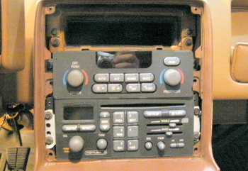
Topic: Digital Automatic HVAC install from 97-2003 grand prix gtp https://www.fiero.nl/forum/Forum2/HTML/099304.html 97-98 have a green display, 99-2003 have a red display This panel has a ground in the back that switches between Fahrenheit and Celsius, and only displays the setting when being adjusted as it normally displays outside temperature
install in progress
I do not have the new prices, but this is what I paid at the pick n pull: The only way I would buy the fan speed controller is at the junkyard; if at all possible, the price list is below from pick-n-pull. (Need to keep an eye out for spares as my winter beater is a 98 gtp with this same controller, only with a green display) Radio- cd player ---------------$10 should have been 15 for cd, charged for a cassette version, half of wiring adapter included Digital hvac controller --------$20 needs backlight switch bulbs replaced, will get to eventually digital fan speed controller --$ 5 they called it a large relay- I was not going to correct them ----------- I would probably be willing to spend 15-20 for a spare locally Temperature door actuator --$ 5 they called it a large relay- I was not going to correct them on this either miscellaneous sensors -------$10 temp and sun load plus wiring cut out to use ----------- I am currently going to try out using intake air temperature sensor for inside cabin.
--Digital hvac controller easily removed after pulling off the surround, remember to take the wiring pigtail --Digital fan speed controller difficult to remove located under dash on passengers side in front to the radiator fan. I removed this by removing the rear bolt, and wiggling the unit out of position, easier if you loosen the front 2 bolts. --Temperature door actuator I went with the passenger side as the driver side appeared difficult to access, Remove the glove box and it will be easily accessed to the centre of the car. --Miscellaneous sensors outside temp in front of radiator, sun load in centre of dash, grab the set I believe the dome version is for the auto climate I am planning on using a intake air sensor for now as the inside air temp sensor, from any car.
IP: Logged
08:32 AM
fieroluke Member
Posts: 357 From: Erlangen, Germany Registered: Mar 2001
I have to ask a few more questions, please forgive me everyone if this is common knowledge in the US...
Is that vehicle common to find or rare? And what kind of tools do I need to remove the glove box? Anything special? I'm asking because I have to bring my tools across the pond, and I obviously don't want to bring the entire tool chest as handluggage
Thanks,
-Oliver
IP: Logged
09:52 AM
Daniel Member
Posts: 282 From: Calgary, Alberta, Canada Registered: Jun 2003
You should only need a normal set of socket wrenches, the socket required is close to 1/4" not exactly sure, and normal screwdrivers: I X and maybe t-15 torks*, Not very common in the junkyard, but this control may be in any grand prix, which is a very common car, more likley in the gtp as it is the higer end model (3.8 supercharged).
------------------ 1988 Fiero GT
IP: Logged
05:48 PM
Riceburner98 Member
Posts: 2179 From: Natick, Ma, USA Registered: Apr 2002
it's been some time... (Remember HUD's?) Very interesting project. I had been thinking of the same thing a long time ago, but I quit for two reasons:
1) How to control the temperature unit 2) The temperature control algorithm
As for #1, can you or anyone else tell me which vehicles one can get these controllers out of and what to expect to pay for them? I'll be in the US in April, and if I have the time, I might drop by a U pull it.
Does your display have a segment for *C instead of *F? Controlling the fan is no issue for me, I had been thinking of getting rid of the resistors too, but what's the point if you keep the stock switch... and once you change the switch, why not change the entire panel... and then #1 and #2 got in the way.
If your unit has a *C symbol, I'd be interested in one or two (I always build one proto and one unit to put in the car).
**************************
One more question regarding your LCD: did you get a data sheet for the panels (voltage, capacitance, etc.)?
I definitely remember HUD's, I still have a ton of parts for them. Lots of Atmel chips and tons of LED displays. My "updates" to try and brighten the LED's didn't work out so great design-wise, and I think they were still a bit dim for the masses, plus the double-reflection thing I think turned some people off.. I probably sold 10 - 12 of them? In the end the trouble -> profit margin wasn't so hot. LOL It's definitely better on these HVAC units, but still it's a large pain in the backside to make lots of them, not to mention the $$ invested. I can see why many devices just aren't viable in this limited "DIY" environment. Learning experiences, but I don't seem to learn from them... Anyway.. I was happy to see your name pop up again in a few threads. Looks like you've been working on some really cool stuff!
I think your question has been answered about where to get the above GM panels.. By "Temperature unit" do you mean the temperature door in the system? I used one of the GM servo motors to move the cable, using a digital potentiometer to output a 0-12v signal to move the servo. The servo motors can be found in many GM cars such as the Grand Prix's mentioned for the auto control headunit, as well as 94+ Chevy Corsicas and similar cars which is where I get mine. (easy to get to, they break right off the driver's side of the HVAC box in 2 seconds)
As for question 2, the temperature control algorithm, I don't have one. The "AUTO" mode and button are fake, and only control a switched output if someone wants to use it for something else. I didn't want to invest the time in the auto controls. I figured I could upgrade them later if I really got that into it by just plugging in more addressable temperature sensors..
I have a spec sheet for the LCD's, no capacitance listed but it has the other important specs. (2.8-3.2v, 1/2 duty, 1/2 bias, 32-128hz framerate, -30*C-80*C operating temp, 100Mohm DC resistance, and of course the pinout.) I use a Phillips PCF8566 generic LCD driver with Atmel Mega's to drive them. Oddly enough, they look best at 2v, but that may be bumped by internal circuitry to the 3v..? I'd be more than happy to send you a few for free if you want them along with the specs. I'll never use all 500. (would be nice though!) You inspired me to get into creating stuff like this with the HUD's. The following picture is the OEM Diablo LCD with all segments on, mine is basically the same except without the company logo in the top left, the "ECON" vertical text, and the "purimax" text inside the recirculate arrows. I think I left off the lower half of the % symbol as well, as I only needed the top circle for degrees. I think the Diablo used that for debugging the solar sensor, to display % sunlight, or perhaps % humidity. I have the ext. temp working on the panels, as well as *C / *F modes, rounded to the nearest degree anyway. Ok, now I'm just getting long winded. LOL If you have any more questions about any of the stuff I have, let me know! Happy to help in any way I can. r i c e b u r n e r 9 8 @ g m a i l (dot) c o m
(Where in the US are you headed?)
[This message has been edited by Riceburner98 (edited 03-31-2009).]
IP: Logged
07:41 PM
PFF
System Bot
Apr 1st, 2009
fieroluke Member
Posts: 357 From: Erlangen, Germany Registered: Mar 2001
you are absolutely right about "mass producing" anything. Lots of $$$ for investment if you don't want to etch and drill all circuit boards (if you do: lots of work nobody will pay for), stacks of parts, and you have to buy many things in odd multiples, so there is always a heap left over that you don't need but that still needs to be paid for. I guess our sense of prices has been spoiled by $50 DVD players and $5 memory sticks. One must remember those things are made by slave labor in the far east to be that cheap. It's hard for people to understand a little Fiero specific device is the price of a Playstation, only because it's made in a quantity of 10 or 50 but not 10,000,000. And that doesn't take into account the countless hours spent writing the code. That's why I design and build my stuff only for myself now (and maybe my Dad ;-), I usually get 1 or 2 samples for free, and I don't have to worry about component cost.
@LCD: Anyway, I'd love to get my hands on a few LCD panels, thanks for the offer (I'll send you a PM with my address)! Maybe I can come up with some sort of regulation algorithm. I'd be happy to share it. Are you programming the Atmel in C? Do you know there is an Atmel Mega with built-in LCD display driver? You could scrap the Philips chip then. I'll be using a freescale CPU with built-in LCD driver - depends on the number of front planes and back planes though. Do you have one backplane and every segment as a separate front plane? I have counted over 40 segments, is that correct?
@other projects: I'm very excited about the OLED trip computer thing, it's making great progress considering I get to spend about an hour on the project twice a week ;-)
@visiting the US: I'm going for the Detroit area. But it doesn't look like I'll have lots of time to visit junkyards...
-Oliver
IP: Logged
08:50 AM
Riceburner98 Member
Posts: 2179 From: Natick, Ma, USA Registered: Apr 2002
Originally posted by fieroluke: @LCD: Anyway, I'd love to get my hands on a few LCD panels, thanks for the offer (I'll send you a PM with my address)! Maybe I can come up with some sort of regulation algorithm. I'd be happy to share it. Are you programming the Atmel in C? Do you know there is an Atmel Mega with built-in LCD display driver? You could scrap the Philips chip then. I'll be using a freescale CPU with built-in LCD driver - depends on the number of front planes and back planes though. Do you have one backplane and every segment as a separate front plane? I have counted over 40 segments, is that correct?
Unfortunately I've been so busy with projects I haven't had time to (re)learn C.. I have the compiler around here somewhere.. I've just been plugging along with assembly language. It works, and the code is fairly compact, but with processor speeds these days that really doesn't matter much. Learning C for programming controllers is the way to go, if not just for the time savings. I need to learn it for work soon, in the past our test equipment has run BASIC Stamps which are OK and all, but too expensive and lacking in features. We use Cypress PSOC chips in a lot of our projects, so I'm going to start using them in the test fixtures. (I'm now a test engineer) I *will* need to get down to it and brush up on my C soon.
There are a few reasons I used the Phillips chip over the Atmel LCD chip... Mainly, I started off using the F355 controller board that I'd made, which already had the Mega8 chip on it, and I had 100 boards made. So I tapped into the serial line and ran the LCD off that at first on a separate board with the Diablo buttons.. Then since that system was already designed and I'd sorted out the registers and lookup tables and such to run the Phillips, I just kept with it on the latest Diablo panels.. If I ever do a redesign I'll likely switch to the Atmel with LCD. Less packages to deal with. The LCD has 2 planes, with I think 21 or 22 segments each. It's an FSTN display I believe, which cost more but I thought it would be better for automotive use.. It's not as "black" as I'd like, the LC has a bit of a blue tinge to it. Guess that's either the liquid or the polarizer film for the FSTN... Still looks great though..
I wouldn't mind working with the Freescale stuff one of these days if I ever get free time. We've been using various DSP chips in our products lately, just so many different choices these days. Some days I like just going home and working with my simple processors. lol
Looking forward to following your progress on your projects, OLED is cool. I had one of the early Pioneer decks with an OLED screen and it was really nice. The demo units in the stores that are on 24/7 had a fair amount of "burn-in" on the screens, but mine was OK after a few years of typical use. I'll keep plugging away at these projects, the only way I stay sane is to just treat it as an expensive hobby, and any $ I make back is "extra". Otherwise it's scary to think how much $ I've got into it. The mini CNC machine had to be the best thing I've ever bought though. If I ever get my Fiero back on the road there's going to be many many machined upgrades.
IP: Logged
01:16 PM
fieroluke Member
Posts: 357 From: Erlangen, Germany Registered: Mar 2001
Yes, development in C is naturally a lot faster than in Assembly, but Assembly is a lot more code efficient of course, even though the compiler is very good.
The OLED is very nice, but expensive. We'll see how bad burn-in is going to be (yet another reason not to sell it to anyone), but this is for my project car which I rarely drive at all. As you wrote it's all hobby (yes, expensive, I'll second that without hesitating)...
Your mini CNC sounds interesting. Did you make any parts for the temperature controller on the CNC? Also, did you measure the current for the Fiero vent control motors?
Best regards.
Oliver
IP: Logged
06:03 PM
Riceburner98 Member
Posts: 2179 From: Natick, Ma, USA Registered: Apr 2002
I made all the parts for the controller on the mini CNC. Even the buttons. .015" cutter for the prototypes, then silicone mold and cast with urethane resin. After a few panels though, I hired out the bodies of the panels to the machine shop we use at work. Even at $100 a set, it's worth it not to have to breathe plastics all day.
Running @ 13v, the mode door draws from .2A - .25A. I tried stalling a non-mounted one with my hand but thought it was going to rip my thumb off, it drew a maximum of .8A. I used 2A Darlington transistors in my F355 board, and 2.6A high-side drivers for the Diablo panels, haven't blown one yet that I know of.
I bought the mini-CNC for about $2,000 US, but it can be had cheaper now that I know where to look, or home-built for even cheaper.
IP: Logged
07:05 PM
Apr 2nd, 2009
fieroluke Member
Posts: 357 From: Erlangen, Germany Registered: Mar 2001
Very interesting! I want to make my own buttons as well, we have a machine shop here at work... ;-)
Did you make a metal mold and then heat up plastic grains into the mold, or did you machine the buttons from one piece? How do you get the symbols on the buttons? Painted on, or using one mold for the symbol, then a second mold to fill in the surrounding material? Are you using rubber "springs" with carbon contact on gold plated board, or micro switches? Do you have any pictures to share? I want to make "stock Fiero grey" buttons, I wonder if I'd get away with recasting the material from recycled GM switches, or if it'd be better to paint the cast buttons grey. Of course I can also part out GM radios if I can find ones with buttons sized the way I want them...
Regarding the HVAC door motors, <1A sounds fine - I like to use integrated smart FETs for high side switches. They're rugged for automotive use, have computer compatible inputs and are virtually indestructible, short circuit protected and have a status output as well. I have bought a couple on eBay in various current models. I have used the one capable of over 15A of current in my power window controller. The current mirror output allowed me to detect motor stall, and they have very little voltage drop. Unlike for HVAC motors, every 0.1V of voltage drop hurts in your power windows i.e. slowing them down.


 I have an HVAC box sitting behind me... When I mounted a servo directly to the top of my 'box I used a GM P/N 16124922 servo motor, which used to be like $40 new, now they re-manufactured them with all plastic parts (used to be a metal shaft) and surface mount components, and the price went to $320... If I remember right it went full hot -> full cold in 60*. At least I think it did..


 = Revin you are not smart enough to do this....
 then...only 499 lcd on the wall !!