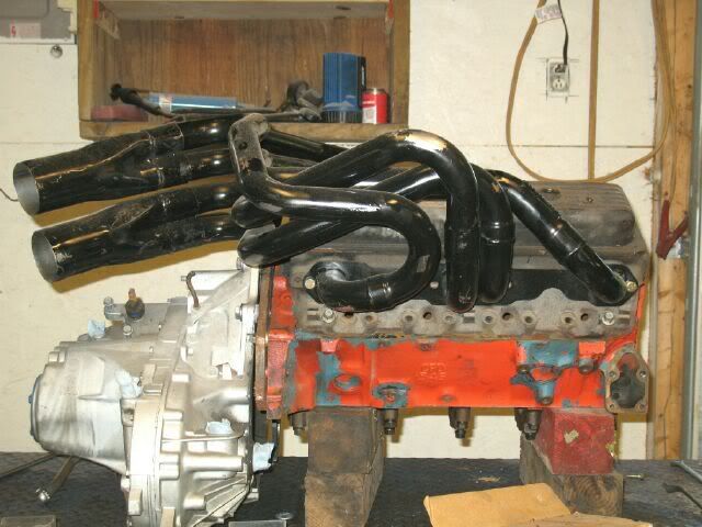
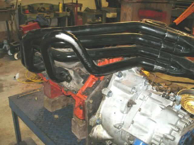
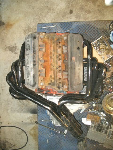
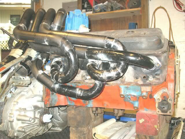
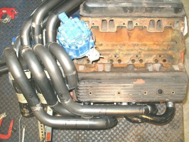
I have been planning to build a set of long tube headers for my SBC car for about a year. After a great deal of searching and some luck, inspiration was found. Most certainly these are not a direct fit, but this is the general style I am after.
Right now, the tubes come out too far from the engine/valve cover to fit within the fiero engine bay and the collectors need to be shorter/angled further down to allow space for a merge collector and clear the strut tower, frame rail, cradle crossmember and sway bar.
The plan is to hack this set up and make the needed tweaks to reroute the tubes for clearance in the fiero engine bay while retaining the equal length and 180 degree design. Once the prototype is made and fits, then I will order a bunch of tubing and weld up the final set.
Honestly I think you are far better off starting from scratch. Those are way off in all areas even if the end up pointing more or less where you need them. I would better take a good look at the ones posted by Jake and try to copy those. I bet that at the end you will end up doing as much cuts and welds or more than starting from scratch. Then also think what gains do you expect based on your current engine mods versus cost of effort. Unless you just want the looks. At least myself I wouldn't get into such big project/investment unless I was going to gain well over 25-30hp. But then I'm not a proffesional welder so I would need to hire
IP: Logged
09:29 PM
fieroguru Member
Posts: 12640 From: Champaign, IL Registered: Aug 2003
Honestly I think you are far better off starting from scratch. Those are way off in all areas even if the end up pointing more or less where you need them. I would better take a good look at the ones posted by Jake and try to copy those. I bet that at the end you will end up doing as much cuts and welds or more than starting from scratch. Then also think what gains do you expect based on your current engine mods versus cost of effort. Unless you just want the looks. At least myself I wouldn't get into such big project/investment unless I was going to gain well over 25-30hp. But then I'm not a proffesional welder so I would need to hire
In the end, the headers will be scratch built for the final version, but the ones above will serve as a rough guide as they are reworked to allow the pipes to flow where I want them. I am not one just to copy what someone else has done, so while I appreciate the info on the other set of headers, that will not be the direction I take.
I already have a baseline of the engine as it is today, so their benefit will be measured once done.
My motivation for this project is: 1. to improve HP (no set target) and set the stage for the next round up upgrades (heads/cam) 2. have a truly unique setup 3. have another metal fabrication project to keep me busy - it is my hobby and I love doing it.
My motivation for this project is: 1. to improve HP (no set target) and set the stage for the next round up upgrades (heads/cam) 2. have a truly unique setup 3. have another metal fabrication project to keep me busy - it is my hobby and I love doing it.
I can appreciate that! To many have lost sight of "because I can"....
IP: Logged
12:16 PM
Jun 21st, 2008
fieroguru Member
Posts: 12640 From: Champaign, IL Registered: Aug 2003
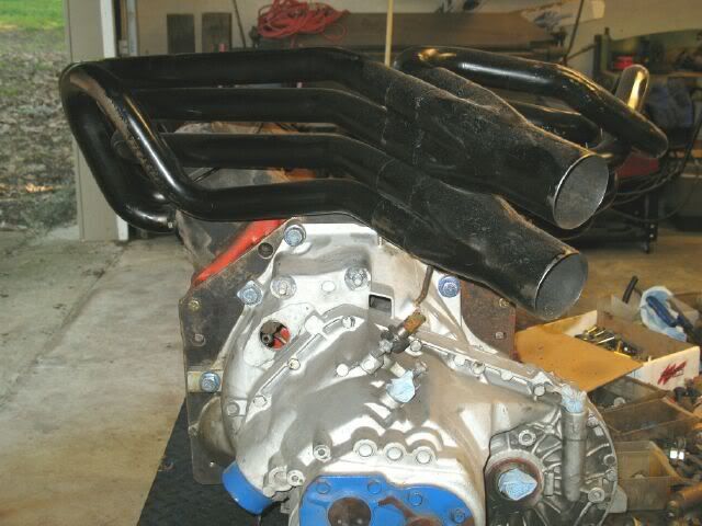
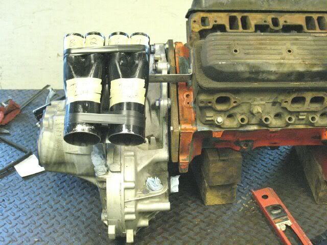
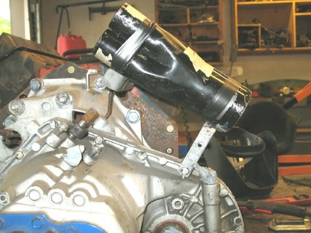
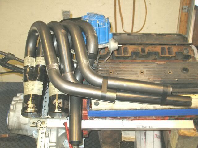
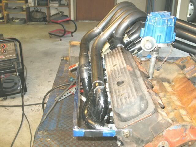
I had about an hour to work on the headers today. Phase 1 is to define the new collector location. I wanted the collectors to dump to the rear of the car and angle down enough for the exhaust to clear the shelf of the trunk.
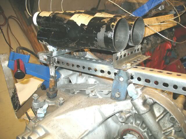
Here is the preliminary mocked up collector position:
Just checking clearances:
In this picture, I put blue tape on the tubes that will go in the lower portion of the right collector. The tubes on that side of the engine will need to come towards the collectors. As the tubes on that side of the engine are routed, I will ensure they clear the firewall.
Some other notes: Original tube locations on the collectors were marked to ensure they go back to their original locations. The tranny dip stick will still clear with the collectors in their current position.
[This message has been edited by fieroguru (edited 06-21-2008).]
IP: Logged
05:36 PM
fieroguru Member
Posts: 12640 From: Champaign, IL Registered: Aug 2003
I was able to get some more preliminary work completed today.
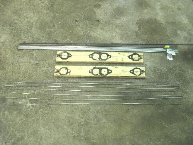
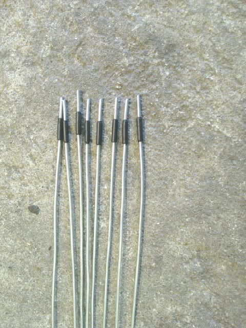
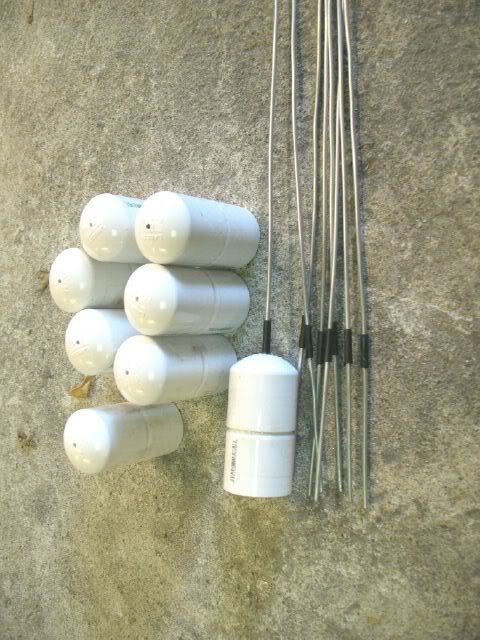
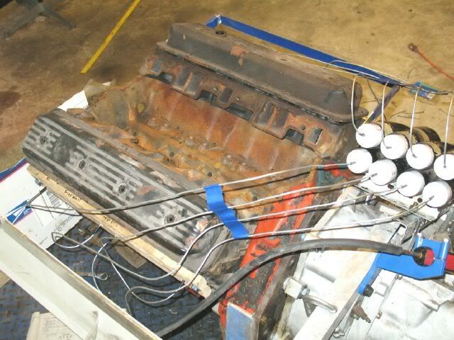
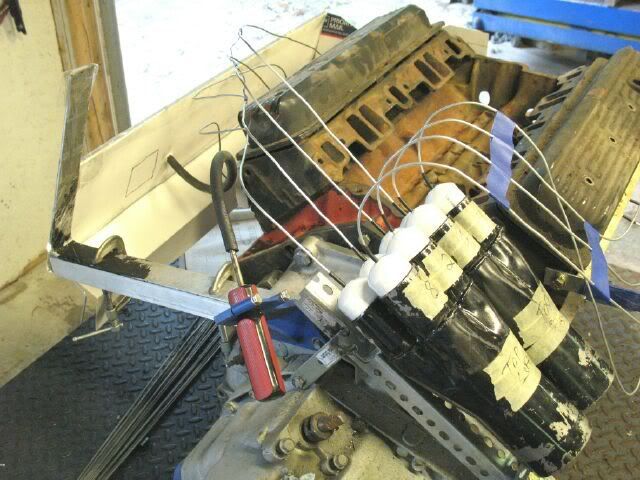
Here are the wire, rods and flanges I will use for the mock up. The wood flanges bolt to the head and have a small hole in the center of the exhaust port. The mockup will be started with the 10ga wire that has been cut to the same length. This stuff is relatively stiff, but still easy to bend. It will be used to route the paths for the tubes. Once I think the routing is done, then I will take the wire and transfer the shape to 3/16" steel rod and again mock up all the tube. The 3/16" is really stiff and should be able to confim the tube paths before I start cutting and welding the actual tubes.
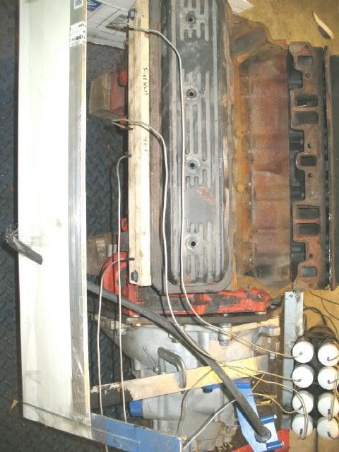
Before starting the wire mockup, I wanted to have a reference of the firewall contour as well as the location of the trunk wall. Having these will ensure proper clearance is left while determining the routing of the tubes.
The trunk wall was easy:
The firewall side took a bit more work. The top of the aluminum bar on the right is a reference point for the deck lid torsion bars. The only part missing is my coolant tube that runs along the firewall (and I might just relocate for the new headers).
I still need to get/make the wood inserts for the tubes at the collectors, then it will be time to bend some wire.
[This message has been edited by fieroguru (edited 06-21-2008).]
IP: Logged
09:02 PM
Jun 22nd, 2008
fieroguru Member
Posts: 12640 From: Champaign, IL Registered: Aug 2003
if possible and it does look like you can with that arrangement, line up your header primaries in the collector so that each one will fire next to the last one in a revolving pattern ..it scavenges the pulses more efficiently that way
IP: Logged
02:31 PM
PFF
System Bot
fieroguru Member
Posts: 12640 From: Champaign, IL Registered: Aug 2003
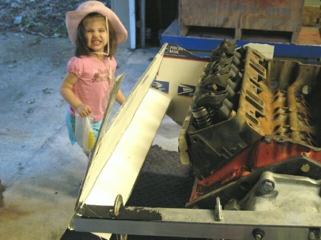
Cool build. Not sure if it's worth it, but it sure looks fun. Have you verified height?
Bob
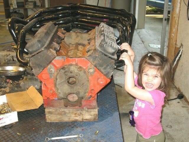
Nice helper..My daughter (4) loves to help, too.
The supplied height is 7 1/2" from the top of the engine block - about the same height as the dist so height was not an issue.
My little helper (Carrera) turned 2 in March and she loves to come out to "daddy's house" and get dirty pickup up loose stuff and placing it where she thinks it goes saying "I fix it"... Watching her grow and learn is simply amazing! Her favorite word today was "firewall".
quote
Originally posted by Erik: if possible and it does look like you can with that arrangement, line up your header primaries in the collector so that each one will fire next to the last one in a revolving pattern ..it scavenges the pulses more efficiently that way
Thanks for the tip. It was easy to get the right collector to pulse counter clock-wise (swapped 1 and 7) and not too much work for the left to pulse clock-wise. I plan to merge the two collectors before the muffler, so I figured having the two rotating into each other would be best... probably doesn't matter and if it is completely wrong, then please speak up.
IP: Logged
05:20 PM
fieroguru Member
Posts: 12640 From: Champaign, IL Registered: Aug 2003
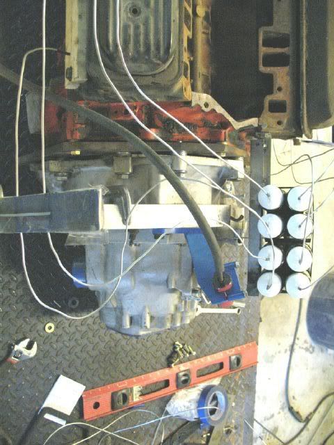
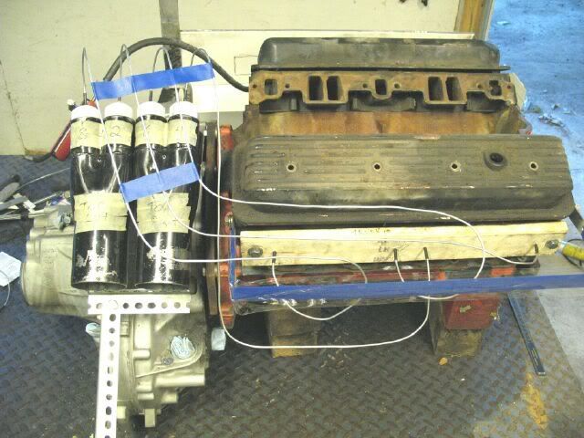
Before starting, I used electrical tape on the ends of the wire to limit depth. Also picked up a bunch of PVC pipe caps, drilled a small hole in the center of each, taped them together in pairs of 2 (made them longer and the wire is supported in 2 spots), and added electrical tape so the wire is flush with the bottom of the caps.
I spent the rest of the day just trial and error working on the tube routing making sure I left room for the shifter bracket and cable. These pics are what I have done so far, but most likely not the final placements. This is a very iterative process and will probably spend most of the week just tweaking and fine tuning the tube placements.
With the current tube placements, the firewall mounted coolant tube needs to be relocated and the down tube for the rear tranny mount (coming off the original starter pad) will need to be reworked some.
Originally posted by Jefrysuko: Ok, yeah... your crazy
That I am... just ask my wife!
quote
Originally posted by Arns85GT: When I was designing my long tube headers I looked at that format and just couldn't figure it out. Glad you have done it. Kind of F1 eh? Arn
I doubt it will sound like an F1, but maybe an old Can Am racer. It should sound different than most other SBC's. I haven't got it all fugured out yet, I am still pondering over the collector location (might come closer to the engine) and the tubing routes - currently they are just not pleasing enough to the eyes so expect to see some additional "what if" scenarios. The pictures will also help me get back to a certain style if 10 changes later I find that I liked #3 the best.
quote
Originally posted by Russ544: Can you build me a set for my Northstar?
That's not just outside the box... that's on another planet........................... I LIKE IT
can't wait to hear the sound clip, Russ
Russ, I am sure you are more than capable of making a set for yourself (probably more so than I am)! I think they would look AWESOME with a set of ITB's, but since you haven't made me a set, my Ramjet setup will just have to do. That reminds me, I need to take a couple of current sound clips so there can be a comparison of what a "simple" exhaust change can do to the exhaust note.
Back to my asylum.
IP: Logged
12:30 PM
fieroguru Member
Posts: 12640 From: Champaign, IL Registered: Aug 2003
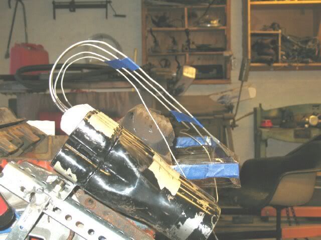
I reworked the collector mockup mounts to allow quickly relocating the collectors towards the engine and up/down on the original angle. It has the same overall distance from the tranny as well.
I moved the collector closer to the engine and up the incline and inch or so. I am kinda liking this routing with all 4 tubes coming out the top together, the inside one drops down below the other 3 tubes as the move towards the engine and travel in a group of 3 until they must diverge to their individual exhaust ports.
One of the main requirements to keep these wire mockups accurate is to make sure all bends are on the same radius the final tubing will be made from. This mockup is getting closer, but I still have quite a bit of slight tweaking to get the radii correct.
[This message has been edited by fieroguru (edited 06-23-2008).]
IP: Logged
08:25 PM
Jun 25th, 2008
fieroguru Member
Posts: 12640 From: Champaign, IL Registered: Aug 2003
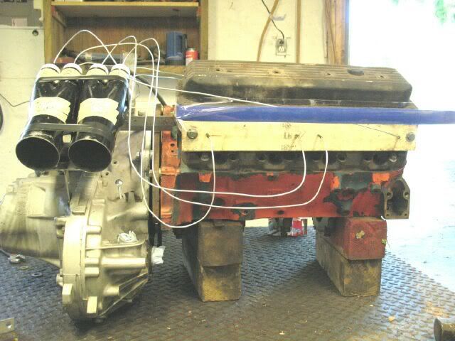
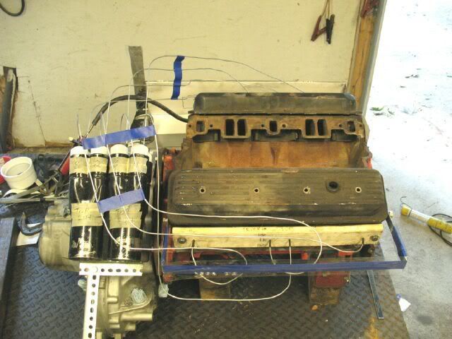
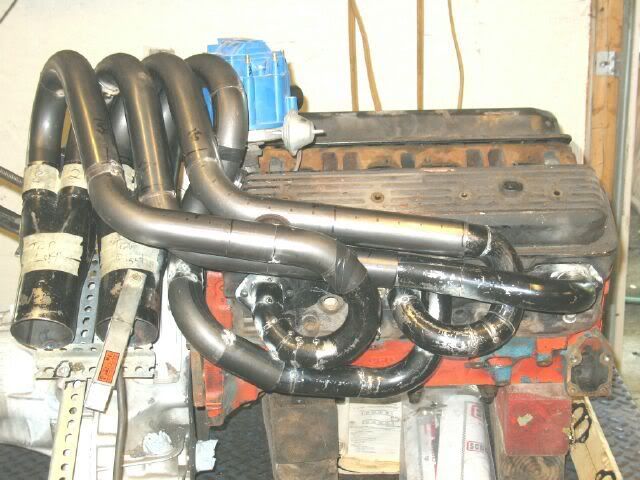
The firewall bank just wasn't doing it for me, so here is the latest version.
Here is what both sides currently look like:
I ordered some additional tubing that might be here by this weekend, if it shows up, I might start mocking up some of the tubing starting with the collectors.
IP: Logged
06:25 PM
Jun 29th, 2008
fieroguru Member
Posts: 12640 From: Champaign, IL Registered: Aug 2003
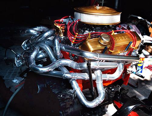
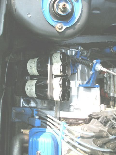
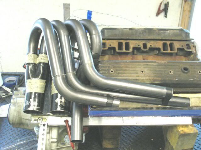
I was able to spend a few hours this morning mocking up the actual header tubes. They are relatively close now, but don't be suprized if I tweak them a 1/4 to 1/8" here and there to make them look their best. Once the collector end is mocked up, I will start on the flange tubes. These headers are a stepped design, where they will start at 1 5/8" at the head and after a certain distance go to 1 3/4" so all the tubes you see are 1 3/4"
Here is some eye candy!
[This message has been edited by fieroguru (edited 06-29-2008).]
IP: Logged
01:49 PM
Russ544 Member
Posts: 2136 From: S.W. Oregon Registered: Jun 2003
I think they would look AWESOME with a set of ITB's, but since you haven't made me a set, my Ramjet setup will just have to do. Back to my asylum.
leave room for them . the idea is still rattling around up there but I haven't run across a manifold that I really like for an afordable price. the tpi manifold that I origanally got for the mockup just hasn't turned me on, and I've been too busy since then to look into it more. I'm really enjoying watching your project. that's gona be cool, so keep plugging away at it.
Russ
IP: Logged
06:46 PM
PFF
System Bot
Jul 12th, 2008
fieroguru Member
Posts: 12640 From: Champaign, IL Registered: Aug 2003
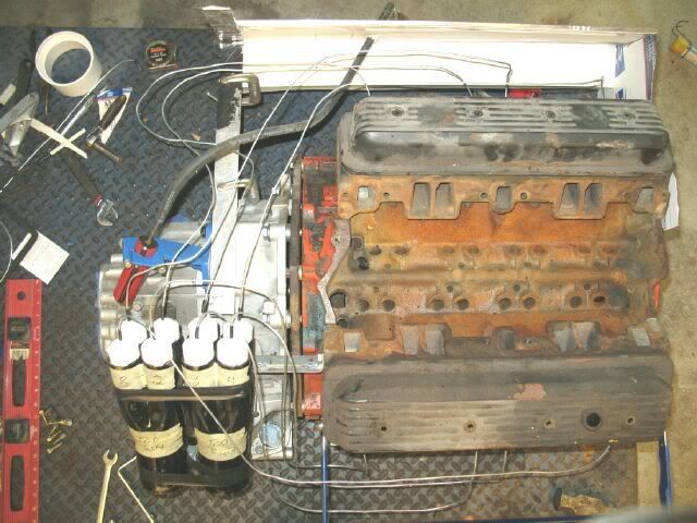
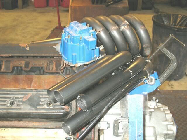
I was able to spend about 4 hrs today working on the headers some more. I tweaked one of the rear tubes slightly and started mocking up the front bank. The general shape is good, but they still need some bends added to get them pointed in the right direction. Then I will cut them all to the same length and then start building the 1 5/8 tubes from the exhaust ports to the ends of the 1 78" pipes and keep them all the same length.
There is a large HEI in the pic, but I run a small remote coil one, so there will be more clearance as well as a heat shield to keep the dist from baking.
I am really starting to like the look of these!
IP: Logged
05:47 PM
joshh44 Member
Posts: 2166 From: Nanaimo, B.C, Canada Registered: Aug 2007
i have a question. are the pipes going over the valve cover? wouldnt be difficult to remove the valve cover?
but i like the way it looks tho looks pretyt mean!
The rear valve cover is still removable, but the front one might not be without loosening the headers. The passenger side decklid hinge bracket also keeps the front valve cover from being removable unless you rock the cradle back to get it out from under the hinge. In 5 years, I have never had a need to remove the valve covers.
[This message has been edited by fieroguru (edited 07-12-2008).]
IP: Logged
07:21 PM
Jul 13th, 2008
fieroguru Member
Posts: 12640 From: Champaign, IL Registered: Aug 2003
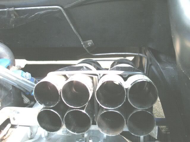
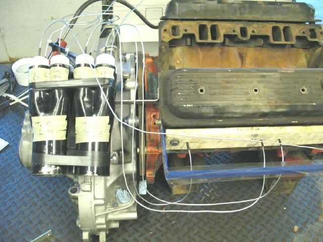
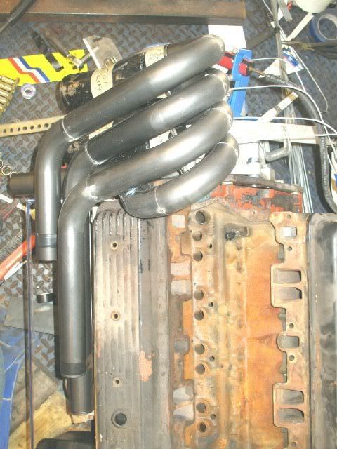
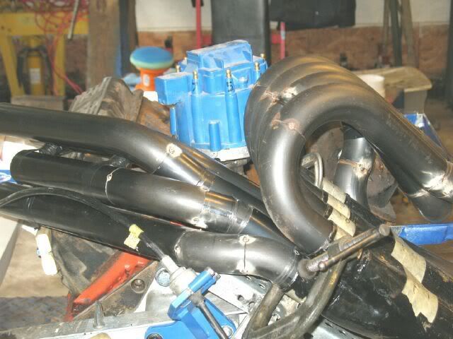
Here are a few pics for the skeptics... rear bundle of snakes and they are equal length in total, as well as the 1 5/8 and 1 3/4 portions.
I hacked up one side of the original 180 headers and used the 1 5/8" tube and flange to mock up the rear side. It is 18ga and the flange is only 1/4" thick, so I am going to buy some better flanges and some additional 1 5/8" 16ga tube to match the 16ga on the 1 3/4". So I will be redoing this part... but atleast now I have parts to copy.
[This message has been edited by fieroguru (edited 07-13-2008).]
IP: Logged
05:07 PM
Formula88 Member
Posts: 53788 From: Raleigh NC Registered: Jan 2001
That's going to be beautiful when you're done. It's almost worth doing for just how good it's going to look.
I agree. Part of my reason for doing this is to have a really impressive/one of a kind exhaust setup. Once they are fully welded, I am planning on smoothing the welds down before being coated so the pipes will be smooth. I have some future plans to make the engine/exhaust visible from the outside to show them off.
IP: Logged
08:07 PM
Russ544 Member
Posts: 2136 From: S.W. Oregon Registered: Jun 2003
That's absolutly NUTS. which is exactly why I like it so much. I'm looking forward to the sound clip for the final nod however I guess you've made provisions for shift cable routing and other similar "incedentals"?
Great job so far, Russ544
IP: Logged
08:12 PM
fieroguru Member
Posts: 12640 From: Champaign, IL Registered: Aug 2003
That's absolutly NUTS. which is exactly why I like it so much. I'm looking forward to the sound clip for the final nod however I guess you've made provisions for shift cable routing and other similar "incedentals"?
Great job so far, Russ544
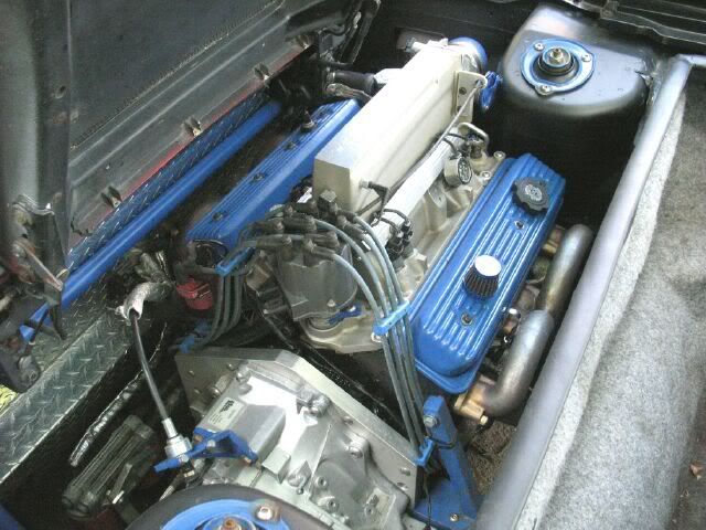
Thanks! The shifter cable will run along side the headers:
To install these, I will have to relocate my coolant crossover tube that is bolted to the firewall, redo the brace for my rear engine mount, relocate the coil, make new custom length spark plug wires, replace rubber fuel lines with steel, and I will most likely make a new engine wiring harness to further tidy things up.
Later this year I will take the car out of commission for the next wave of upgrades.
IP: Logged
09:03 PM
PFF
System Bot
Jul 14th, 2008
Russ544 Member
Posts: 2136 From: S.W. Oregon Registered: Jun 2003
A buddie of mine (Mick) owns a hot rod shop, as well as doing custom exhaust work. if you want a top chopped on a 49 Merc, or all metal flairs on a Chevell, this is the guy to see.... What was the old guys name on American Hot rod? the grumpy old metal worker?... anyway, that guy could be my buddie Mick. he doesn't give out compliments unless it's pretty dang unusual, and very well done. anyway, I was showing Mick the pictures of your project and his eyes opened up a bit as he says "that's pretty cool ! ". He does want to know why you'r using two different sizes of tubing however. why the step?
A buddie of mine (Mick) owns a hot rod shop, as well as doing custom exhaust work. if you want a top chopped on a 49 Merc, or all metal flairs on a Chevell, this is the guy to see.... What was the old guys name on American Hot rod? the grumpy old metal worker?... anyway, that guy could be my buddie Mick. he doesn't give out compliments unless it's pretty dang unusual, and very well done. anyway, I was showing Mick the pictures of your project and his eyes opened up a bit as he says "that's pretty cool ! ". He does want to know why you'r using two different sizes of tubing however. why the step?
Cheers, Russ
For the life of me I can not remember the name of the sheetmetal guy from American Hot rod... I am glad your buddy thinks these headers are cool and he has a very good idea of what it took to get them to this stage. Once I get them done, I suspect there will be more questions about the headers than anything else in the car...
The stepped tubes came about due to a couple of factors. 1 5/8" tubes at the heads helped from a packaging standpoint. With the collector location, these are longer than I would have liked and didn't want them to be a restriction.
http://headerdesign.com/index.asp has a nifty program that you enter your engine size, compression, planned HP and RPM of HP peak and it will spit out the primary diameter/length and collector diameter/length.
For a 350 +.060", 10.2:1, 350 hp @ 5200 rpm Performance factor = 1 - To maximize lowend torque - Primaries 1.39" ID @ 40.6" in length, 2.06" collector 13.4" long Performance factor = 6 - street/strip with manual and low gears - Primaries 1.46" ID @ 36" in length, 2.29" collector 14.7" long Performance factor = 10 - all out drag race - Primaries 1.51" ID @ 33.5" in length, 2.45" collector 15.5" long
With 1 5/8" 16ga tube, the ID is roughly 1.50, so ideally the headers needed to be 36" in length for a 350 hp engine as listed above. I needed mine to be longer and want some room to grow HP wise for future cam/head upgrades.
For a 350 +.060", 10.2:1, 450 hp @ 5600 rpm Performance factor = 1 - To maximize lowend torque - Primaries 1.50" ID @ 38.3" in length, 2.27" collector 13.0" long Performance factor = 6 - street/strip with manual and low gears - Primaries 1.58" ID @ 34.2" in length, 2.51" collector 14.2" long Performance factor = 10 - all out drag race - Primaries 1.63" ID @ 31.9" in length, 2.68" collector 15.0" long
At 450 hp, the 1 5/8" primaries (1.50" ID) would be maximizing lowend too much (and still be too long). The 1 3/4" 16 ga primaries (1.625 ID) would be at full race level at 32". So with 12" of 1 5/8 and 30" of 1 3/4 16ga they should be somewhere in the middle at the 450 hp level.
Until the cam/head change, they will be close to full race... and I am curious to what the pros and cons will be on the dyno and on the street.
IP: Logged
07:33 PM
fieroguru Member
Posts: 12640 From: Champaign, IL Registered: Aug 2003
He was actually pretty active on PFF 5 or 6 years ago.
I talked to him several months ago on the phone & he said all that pipe area did create a lot of heat in the engine compartment.
Archie
Dealing with the additional heat is a concern. They will be ceramic coated in the end, but that only does so much. Wrapping them would help, but would really take away from the apearance. There will be heat shields to protect the dist and shifter cable and the harness/fuel lines will be kept as far away as possible. They are up high so it should simply be a matter of getting the heat out the top side and I have a couple of ideas for that.
IP: Logged
07:46 PM
Jul 20th, 2008
linuxpowered88 Member
Posts: 1220 From: Johnson City , TN , USA Registered: Sep 2007
I think your progress is the eptimone of what a Fiero should be ..please keep it dual dependant on firing pulses, 180 degree ..not into a common muffler ..
[This message has been edited by Erik (edited 07-20-2008).]
IP: Logged
05:46 AM
Erik Member
Posts: 5628 From: Des Moines, Iowa Registered: Jul 2002
I think your progress is the eptimone of what a Fiero should be ..please keep it dual dependant on firing pulses, 180 degree ..not into a common muffler ..
Thanks!
I am still undecided on if I will keep them as true duals or merge them into a single exhaust.
If I merge them, the plan would be to 90 towards the passenger side out of the collectors and have the two sides merge into a common 3" pipe as they make the bend. Then they would go into a resonator and on the passenger side do a 180 bend and connect to the existing 3" in dual 2 1/2" out muffler. This setup should help keep the volume level close to what I have now (which is rather loud), and if there would come a time that I needed to pass tail pipe emissions (the headers would never pass the visual), then I could install a highflow cat in place of the resonator.
If I were to run them true duals, I would want them to be equal length as well, which will be a challange since they both will dump closer to the driver side and I like the balanced look of the dual megaphones in the stock location. I think the right collector could turn 90, go across the car, do a 180 on the passenger side and then come back across the car with a muffler mounted under the rear cross memeber and exit on the driver side. The Left/Driver side could turn right with a 90 to the right, into a mullfer in the general stock location and exit on the passenger side. There would need to be a few additional bends added to equalize the lengths... but I still have a lot more thinking for this. I haven't done much to the headers this week, been busy getting the SBC car ready for the 25th, cleaning/oganizing the garage to make room for another 88 fiero (4.9 install for a friend) and working on the honey do list in preperation for our 2nd child that should be joining us in mid august.