Engineering Investigation On The 2006/2007 ECM E67 Module - keywords controller part restriction #PIP4045A - (02/23/2007)
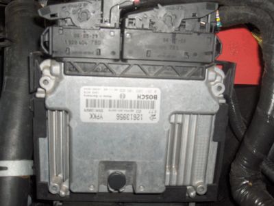
PQC-Restriction E67 ECM PART # 12605843
This is what happens when Tech replace GOOD PARTS.
The E-67 ECM is used on the following vehicles: The 2007 GMC Acadia and Saturn Outlook use the E67 with the 3.6L LY7 engine, as well as the Pontiac G6, Saturn Aura, with the 3.6L LY7 and 2.4L LE5, the 2007 Chevrolet Impala (GMX211) Monte Carlo (GMX231) and Pontiac Grand Prix only use the E67 with the 5.3L LS4 Gen IV smallblock. All 2.4L LE5 use the E67 controller, the 2006/2007 Chevrolet Cobalt, HHR, Pontiac Solstice, Pursuit, G5, Saturn Sky and ION. (2.2L L61 and 2.4L LE5) as well as the 2007 Chevrolet Trailblazer and GMC Envoy with the 5.3L LH6 and 6.0L LS2). All 2007 : Saturn Vue and Aura with the 2.4L LAT BAS Hybrid applications use the E67 controller. All 2007 Cadillac Premium V8 applications use the E67 controller (4.6L L37, LD8, LH2, and LC3) In 2006, only the Cadillac DTS (LD8 and L37) and Buick Lucerne (4.6L LD8) used the E67 controller. All 2006/2007 GMT201 minivans - Uplander , Relay, and Terraza with 3.9L (LZ9, (and 07 LGD) engine use the E67. The 2006 / 2007 Cadillac CTS with the 6.0L LS2 use E67 controllers.
IP: Logged
09:37 AM
Jul 1st, 2007
fierochild Member
Posts: 346 From: Woodstock, Ga. USA Registered: Mar 2001
Any updates? SCCA has changed the rules for 2008 allowing open ECMs. This would be great if it could be made to work with my 3.4 pushrod engine with distributor.
To add into the discussion, I'm venturing into programming a custom ECM for the duke engine using a pic16f877a which has a 35 instruction 5MHz core. Its definitely nowhere close to as powerful as the ECMs ryan is looking at, but its a helluvalot more powerful than the stock ECM core.
I hate the current ECM with a passion due to its primitive nature (high idle, anyone?!!), so boredom got the best of me. It will give me plenty of experience writing code for them, at least, even though its for a custom (and more than likely one-off) ECM board and nonstandard CPU.
I'm currently working on the kernel which uses a round-robin scheduler to select between sensor update, engine management parameter update, injector control, ignition control, IAC driver, error checking and logging, and ALDL linkup processes including process requeueing for processes that need an extra "timeslice". (Actually, the scheduler switches a task when the process either kills itself to respawn during the requeueing event, or it terminates. The context switch is not based on a timer interrupt.)
[This message has been edited by AP2k (edited 08-06-2007).]
Ryan, I don't know if you know already (you probably do.) but you can tune this new ECM with HPtuners. The Cobalt SS Supercharged and SS 2.4 guys use this software, and you can pretty much modify anything. I don't know if you've looked into it or not, but www.hptuners.com is the site!
Have fun, and keep us posted.
Sean
IP: Logged
05:55 PM
Aug 25th, 2007
AJxtcman Member
Posts: 1098 From: Rock Hill SC Registered: Nov 2006
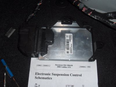
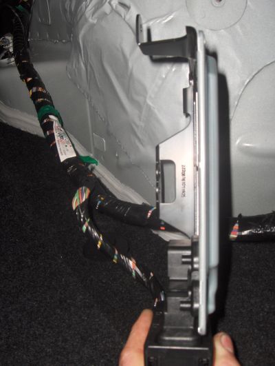
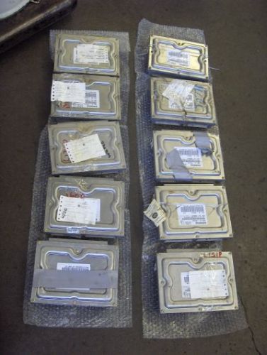
Hi Ryan. I have some more pictures. . First this is a E77 ECM use in 07+ 3.6L Caddy's . . Next is a GM high speed LAN Suspension ECM. The height sensors are Modules on this car and they are also GM high speed LAN. This is neat and almost like a wireless setup. On this car it has small modules that had been sensors in the past. All they need is a Power, Ground, and LAN connections. No more 5v ref, low ref, signal. This really cuts down on the amount of wires in the car. . . . This is my newest lot of 00 to 03 PCM's
Does the 16-bit CPU have connections to anything outside the box? If so, I theorize that it may be used to log driving habit data and save it to memory instead of using a separate process on a single core along with the rest of the program. What are your thoughts on its purpose? It bothers me that there are two cores on it with completely different functionality.
So, I suppose I'm the only other person seriously interested in programming? Not that it matters to me how many there are. This would beg the question as to what compilers are available and which would be used. Wind River and Green Hills are two commercial products that support Freescale C, but they dont list prices. Freescale itself has a compiler toolkit for $6k, though... You can also get the free compiler, but its limited to a 16K bin. (I suppose 16k would be sufficient to run an older engine)
So.... how goes it, Ryan?
IP: Logged
03:15 PM
rockcrawl Member
Posts: 2528 From: Lehigh Valley, PA Registered: Jul 2000
I'm interested in putting some time into this. Deciphering GM's high speed LAN protocol will be a very important part of this. I believe it is based on CAN 2.0. It will take some specialized equipment to log the nearly 2000 messages per second that are flying around the LAN. Each message has an 11 or 29 bit identifier followed by data. Each computer (node) on the bus receives all messages and chooses to either process or ignore them. There is no way of knowing which node sent the message or which node the message is intended for. Figuring out the meaning of each identifier will be the difficult part. Does anyone here have access to the SAE papers? I believe some of the protocol is mandated and available from SAE. Surely the big tuner companies already have it figured out, but they are not going to share the info.
quote
I am doubting it has much along the lines of a video output controller
It doesn't need one. The LAN bus is full of all sorts of data available to any node that wants to make use of it. It would be simple to build a video interface to capture and display data from the LAN, but the first step is figuring out the identifiers on each packet of data. The aftermarket audio companies are already doing this, a good example is the Scoshe GM LAN interface. Another example is the new line of gauges that plug into the data port. Imagine installing a full set of aftermarket gauges with just three wires to hook up. It's already being done.
IP: Logged
05:25 PM
PFF
System Bot
AJxtcman Member
Posts: 1098 From: Rock Hill SC Registered: Nov 2006
Did I read this correctly? Please tell me I didn't. An inexpensive ECM and an inexpensive "E" trans controller? I assume this would be OBDII only? I am really trying to find something that can be used for my future complete 3400 swap (N/A and then turbo later) that can also control a 4T60E trans.
IP: Logged
09:52 PM
ryan.hess Member
Posts: 20784 From: Orlando, FL Registered: Dec 2002
I'm interested in putting some time into this. Deciphering GM's high speed LAN protocol will be a very important part of this. I believe it is based on CAN 2.0. It will take some specialized equipment to log the nearly 2000 messages per second that are flying around the LAN. Each message has an 11 or 29 bit identifier followed by data. Each computer (node) on the bus receives all messages and chooses to either process or ignore them. There is no way of knowing which node sent the message or which node the message is intended for. Figuring out the meaning of each identifier will be the difficult part. Does anyone here have access to the SAE papers? I believe some of the protocol is mandated and available from SAE. Surely the big tuner companies already have it figured out, but they are not going to share the info.
It doesn't need one. The LAN bus is full of all sorts of data available to any node that wants to make use of it. It would be simple to build a video interface to capture and display data from the LAN, but the first step is figuring out the identifiers on each packet of data. The aftermarket audio companies are already doing this, a good example is the Scoshe GM LAN interface. Another example is the new line of gauges that plug into the data port. Imagine installing a full set of aftermarket gauges with just three wires to hook up. It's already being done.
Logging is not difficult. A PC and a serial port can take care of that.
Decyphering will be the difficult part, indeed.
However, I believe that a microcontroller, a few choice resistors, and a differential amplifier will suffice for figuring out which signal came from where. That will make our job MUCH simpler.
IP: Logged
02:21 AM
darkhorizon Member
Posts: 12279 From: Flint Michigan Registered: Jan 2006
Did I read this correctly? Please tell me I didn't. An inexpensive ECM and an inexpensive "E" trans controller? I assume this would be OBDII only? I am really trying to find something that can be used for my future complete 3400 swap (N/A and then turbo later) that can also control a 4T60E trans.
Powertuner/HPtuners/efilive and a obd2 pcm would do that flawlessly. You could even step up to running a performance minded 4t65e-hd, using a impalla pcm code. the stock 65e can sorta easily handle 300 whp out of a supercharged 3800 in a heavy wbody.
OBD1 would be slightly cheaper, but you might be stuck with not so great base code for your motor. OBD1 would be the best if if you want to stick with a 60e.
I want to point out now that for a FOSS project, SAE/GM/etc will be VERY displeased with us disclosing the CAN codes. It is very likely that they will subpoena research to ascertain whether or not we actually did our own research or just copied papers we shouldnt have access to. Copyright infringement is a bad thing.
For this same reason projects such as Nouveau have to use user participation to execute certain graphics commands with certain things in their registers and see how it changes. Its called "clean room" reverse engineering and its going to be the only way we can legally publish this stuff as a binary.
I seem to have some access to some SAE papers through my university. I'll be poking around to see what we need to be looking for.
I did find a cool abstract:
quote
Ultra-low NOx and smokeless operation at higher loads up to half of the rated torque is attempted with large rates of cold exhaust gas recirculation (EGR). NOx decreases below 6 ppm (0.05 g/kW h) and soot significantly increases when first decreasing the oxygen concentration to 16 per cent with cold EGR. However, after peaking at 12-14 per cent oxygen, soot then decreases sharply to essentially zero at 9-10 per cent oxygen while maintaining ultra-low NOx, regardless of fuel injection quantity and injection pressure. However, at higher loads, with the oxygen concentration below 9-10 per cent, the air-fuel ratio has to be over-rich to exceed half of the rated torque, and thermal efficiency, CO, and THC deteriorate significantly. As the EGR rate increases, exhaust gas emissions and thermal efficiency vary with the intake oxygen content rather than with the excess air ratio. Longer ignition delays due to either advancing or retarding the injection timing reduced the smoke emissions, but advancing the injection timing has the advantages of maintaining the thermal efficiency and preventing misfiring. A reduction in the compression ratio is effective to reduce the in-cylinder temperature and increase the ignition delay as well as to expand the smokeless combustion range in terms of EGR and i.m.e.p. (indicated mean effective pressure). [ABSTRACT FROM AUTHOR]
[This message has been edited by AP2k (edited 09-05-2007).]
Short answer: Everything. ABS/TCM modules, gauge clusters even some switches are set up sot that triggering them kicks out CAN signals instead of simply breaking a circuit.
The worst part of this is that gauge clusters look for info from the various stuff and will throw lights and so forth if they don't receive SOH (status of health) updates from various components. This goes in reverse for other modules, too. Some cars won't start period, without the gauge cluster in place. A lot of modules crosstalk even when they don't have anything relevant to say to each other. They frequently just talk to each other as a preventative maintenance measure. Sample conversation: Gauge Cluster: "Hey ABS, are you there?" ABS module: "Yeah, I'm here, are you there?" Gauge Cluster: "Of course I am, are you still there?" Gauge Cluster: "Hello?" "No?" (illuminates ABS light, even if ABS is 100% functional, just because communication is lost)
Kurt
[This message has been edited by KurtAKX (edited 09-06-2007).]
IP: Logged
05:44 PM
Sep 7th, 2007
AJxtcman Member
Posts: 1098 From: Rock Hill SC Registered: Nov 2006
Data Link Communications Description and Operation Circuit Description The data link connector (DLC) allows a scan tool to communicate with the class 2 serial data line. The serial data line is the means by which the microprocessor-controlled modules in the vehicle communicate with each other. Once the scan tool is connected to the class 2 serial data line through the DLC, the scan tool can be used to monitor each module for diagnostic purposes and to check for diagnostic trouble codes (DTCs). Class 2 serial data is transmitted on a single wire at an average of 10.4 kbps. This value is an average; class 2 uses a variable pulse width modulation to carry data and depending on the message it may operate faster or slower. The bus will float at a nominal 7 volts during normal operation. Each module can pull this lower during the transmission. The bus is not at battery positive voltage or ground potential during normal operation. When the ignition switch is in RUN, each module communicating on the class 2 serial data line sends a state of health (SOH) message every 2 seconds to ensure that the module is operating properly. When a module stops communicating on the class 2 serial data line, for example, if the module loses power or ground, the SOH message it normally sends on the data line every 2 seconds disappears. Other modules on the class 2 serial data line, which expect to receive that SOH message, detect its absence; those modules in turn set an internal DTC associated with the loss of SOH of the non-communicating module. The DTC is unique to the module which is not communicating; for example, when the inflatable restraint sensing and diagnostic module (SDM) SOH message disappears, several modules set DTC U1088. Note that a loss of serial data DTC does not normally represent a failure of the module that set it.
On some vehicles, if the powertrain control module (PCM) is unable to communicate with the vehicle theft deterrent (VTD) system after the vehicle has started, the PCM will consider the VTD system to be malfunctioning. The PCM will enter a fail enable state and will command the security indicator to illuminate. When the PCM is in a fail enable state, the vehicle will NOT stall or stop running. If the PCM is in a fail enable state when the ignition is switched OFF, the PCM will remain fail enable until communications with the VTD system has been restored. When the PCM is in a fail enable state, the VTD system is NOT active and the vehicle will start. This feature is NOT available on all GM vehicle lines.
Data Link Connector (DLC) The data link connector (DLC) is a standardized 16 cavity connector. Connector design and location is dictated by an industry wide standard, and is required to provide the following:
Scan tool power battery positive voltage at terminal 16. Scan tool power ground at terminal 4. Class 2 serial data at terminal 2. Common signal ground at terminal 5. Class 2 Serial Data Line A total list of the control modules on the class 2 serial data line can include the following:
The audio amplifier The cellular telephone module w/UV8 The dash integration module (DIM) The digital radio receiver The driver door module (DDM) The driver door switch assembly (DDSA) The electronic brake control module (EBCM) The electronic suspension control module (ESC) The front passenger door module (FPDM) The inflatable restraint sensing and diagnostic module (SDM) The instrument panel cluster (IPC) The instrument panel integration module (IPM) The HVAC control module - auxiliary The left middle door module (LMDM) w/V4U The left rear door module (LRDM) The memory seat module (MSM) w/A45 The powertrain control module (PCM) The radio The rear integration module (RIM) The remote control door lock receiver (RCDLR) The remote playback device CD changer The right middle door module (RMDM) w/V4U The right rear door module (RRDM) The steering column module The theft deterrent control module The vehicle communication interface module (VCIM) The window switch - front passenger w/armored car The class 2 serial data line is a ring/star configuration with discrete circuits entering and leaving each module. This allows communications to the modules on the ring portion of the class 2 serial data circuit if one of the 2 discrete circuits is open. The following modules are on the ring portion of the class 2 serial data circuit. Therefore if there is an open in the class 2 serial data circuit communication will still occur:
The dash integration module (DIM) The digital radio receiver The electronic brake control module (EBCM) The inflatable restraint sensing and diagnostic module (SDM) The instrument panel cluster (IPC) The instrument panel integration module (IPM) The powertrain control module (PCM) The radio The remote playback device CD changer The following modules are connected to the star portion of the class 2 serial data circuit by splice packs and have only one communication line connection to the class 2 serial data circuit. Therefore if the class 2 serial data line is open to any of these modules communication will not occur:
The audio amplifier The cellular telephone module w/UV8 The driver door module (DDM) The driver door switch assembly (DDSA) The electronic suspension control module The front passenger door module (FPDM) The HVAC control module - auxiliary The left middle door module (LMDM) w/V4U The left rear door module (LRDM) The memory seat module (MSM) w/A45 The rear integration module (RIM) The remote control door lock receiver (RCDLR) The right middle door module (RMDM) w/V4U The right rear door module (RRDM) The steering column module w/N37 The theft deterrent control module The vehicle communication interface module (VCIM) The window switch - front passenger w/armored car
IP: Logged
06:24 AM
AJxtcman Member
Posts: 1098 From: Rock Hill SC Registered: Nov 2006
Data Link Communications Description and Operation Circuit Description The communication among control modules is performed primarily through the GMLAN high speed serial data circuit and the GMLAN low speed serial data circuits. The modules that need real time communication are attached to the high speed GMLAN network. The body control module (BCM) is the serial data gateway between the networks. The purpose of the gateway is to translate serial data messages between the GMLAN high speed buss and the GMLAN low speed buss. The Local Interconnect Network (LIN) is another serial data communication network used on this vehicle which is dedicated to the door/power windows subsystem. Below are more detailed descriptions of the individual networks. The gateway will interact with each network according to that network's transmission protocol. Refer to Body Control System Description and Operation for more information about the gateway.
GMLAN High Speed Circuit Description The data link connector (DLC) allows a scan tool to communicate with the high speed GMLAN serial data circuit. The serial data is transmitted on two twisted wires that allow speed up to 500 Kb/s. The twisted pair is terminated with 120 ohms resistors. One of the resistors is located in the rear fuse block, and others are internal to the engine control module (ECM), distance sensing cruise control (DSCC) module , and the body control module (BCM). The resistors are used to reduce noise on the High Speed GMLAN bus during normal vehicle operation. The high speed GMLAN is a differential bus. The high speed GMLAN serial data bus (+) and high speed GMLAN serial data (-) are driven to opposite extremes from a rest or idle level. The idle level, which is approximately 2.5 volts, is considered recessive transmitted data and is interpreted as a logic 1. Driving the lines to their extremes, adds one volt to the high speed GMLAN serial data bus (+) and subtracts one volt from the high speed GMLAN serial data bus (-) wire. This dominant state is interpreted as a logic 0. GMLAN network management supports selective start up and is based on virtual networks. A virtual network is a collection of signals started in response to a vehicle event. The starting of a virtual network signifies that a particular aspect of the vehicles functionality has been requested. A virtual network is supported by virtual devices, which represents a collection of signals owned by a single physical device. So, any physical device can have one or more virtual devices. The signal supervision is the process of determining whether an expected signal is being received or not. Failsofting is the ability to substitute a signal with a default value or a default algorithm, in the absence of a valid signal. Some messages are also interpreted as a heartbeat of a virtual device. If such a signal is lost, the application will set a no communication code against the respective virtual device. This code is mapped on the Tech 2 screen as a code against the physical device. Note: a loss of serial data DTC does not represent a failure of the module that the code is set in.
GMLAN Low Speed Circuit Description The data link connector (DLC) allows a scan tool to communicate with the low speed GMLAN serial data circuit. The serial data is transmitted over a single wire to the appropriate control modules. The transmission speed for GMLAN low speed is up to 83.33 Kb/s. Under normal vehicle operating conditions, the speed of the buss is 33.33 Kb/s. This protocol produces a simple pulse train sent out over the GMLAN low speed serial data bus. When a module pulls the buss high, 5 volts, this creates a dominant logic state or 0 on the buss. When the buss is pulled low, 0 volts, it is translated as a recessive logic state or 1. To wake the control modules connected to the GMLAN low speed serial data buss, a high voltage wake up pulse is sent out over the buss, the voltage level of the pules is +10 volts. Modules connected to the GMLAN low speed buss can be part of a virtual network as described in the previous paragraph. The modules on the GMLAN low speed serial data buss are connected to the buss in a parallel configuration.
Local Interconnect Network (LIN) Description The driver door module (DDM) and the front passenger door module (FPDM) communicate with window motors on the local interconnect network bus 1 and the local interconnect network bus 2 circuits respectively. The DDM LIN buss is connected to all window motors on its side of the vehicle, while the FPDM LIN buss is connected to the other window motors. Communication on this network is only between the door modules and the window motors. The window motors are in effect modules. The window motor modules do not communicate on any other data buss; therefore the door modules, which also communicate on the low speed GMLAN serial data buss will perform all communication with each other, the motors, the body control module (BCM) (gateway) and the scan tool including setting LIN buss DTCs.
Keyword 2000 Circuit Description The keyword protocols utilize a single wire bi-directional data line between the module and the scan tool. The message structure is a request and response arrangement. The keyword serial data line is used for scan tool diagnostics of the climate control seat module (CCSM) only. Other modules on the vehicle do not exchange data on this circuit.
Data Link Connector (DLC) The data link connector (DLC) is a standardized 16-cavity connector. Connector design and location is dictated by an industry wide standard, and is required to provide the following:
• Pin 1 GMLAN low speed communications terminal
• Pin 4 Scan tool power ground terminal
• Pin 5 Common signal ground terminal
• Pin 6 High speed GMLAN serial data bus (+) terminal
• Pin 7 keyword 2000 serial data bus terminal
• Pin 14 High speed GMLAN serial data bus (-) terminal
• Pin 16 Scan tool power, battery positive voltage terminal
Serial Data Reference The scan tool communicates over the various busses on the vehicle. When a scan tool is installed on a vehicle, the scan tool will try to communicate with every module that could be optioned into the vehicle. If an option is not installed on the vehicle, the scan tool will display No Comm for that options control module. In order to avert misdiagnoses of No Communication with a specific module, refer to Data Link References for a list of modules, the busses they communicate with, and the RPO codes for a specific module.
Body Control System Description and Operation The body control system consists of the body control module (BCM), communications, and various input and outputs. Some inputs, outputs and messages require other modules to interact with the BCM. The BCM also has discrete input and output terminals to control the vehicle's body functions. The BCM is wired to the GMLAN High speed serial data buss and the GMLAN Low speed serial data buss and acts as a gateway between them. If the BCM does not communicate the vehicle will not start due to the inability of the Engine/Powertrain Control Module (ECM/PCM) and Vehicle Theft Deterrent (VTD) Control Module to communicate without the BCM providing the gateway function.
Power Mode Master This vehicles BCM functions as the power mode master (PMM). The ignition switch is a low current switch with multiple discrete ignition switch signals to the PMM for determination the power mode that will be sent over the serial data circuits to the other modules that need this information, and so the PMM will activate relays and other direct outputs of the PMM as needed. Refer to Power Mode Description and Operation for a complete description of power mode functions.
Serial Data Gateway The BCM in this vehicle functions as a gateway or translator. The purpose of the gateway is to translate serial data messages between the GMLAN high speed buss and the GMLAN low speed buss for communication between the various modules. The gateway will interact with each network according to that network's transmission protocol.
One example of this necessary communication is the communication between the Engine/Powertrain Control Module (ECM/PCM) which is high speed serial data and Vehicle Theft Deterrent (VTD) Control Module which is low speed serial data. If these modules can not exchange information, the vehicle will not start.
Communication between the BCM and a scan tool can be on the high speed GMLAN network or low speed GMLAN network. If one network is lost, the BCM can still communicate with the scan tool. A lost communication DTC typically is set in modules other than the module with a communication failure.
Body Control Module The various body control module (BCM) input and output circuits are described in the corresponding functional areas indicated on the BCM electrical schematics. Some BCM functions with the subsystems may be as a gateway only or as an enable for the system. The BCM related systems/subsystems include, but are not limited to the following:
• Antilock brake system (ABS)--Refer to ABS Description and Operation .
• Automatic day-night mirror--Refer to Automatic Day-Night Mirror Description and Operation .
• Cruise control system--Refer to Cruise Control Description and Operation .
• Electrical power management (EPM)--Refer to Electrical Power Management Description and Operation .
• Exterior lighting--Refer to Exterior Lighting Systems Description and Operation .
• Horn system --Refer to Horns System Description and Operation .
• HVAC--Refer to Air Delivery Description and Operation and Air Temperature Description and Operation .
• Instrument cluster indicator control--Refer to Instrument Panel Cluster (IPC) Description and Operation .
• Interior lighting--Refer to Interior Lighting Systems Description and Operation .
• Power door lock system --Refer to Power Door Locks Description and Operation .
• Rear window defogger system --Refer to Rear Window Defogger Description and Operation .
• Redundant steering wheel controls --Refer to Steering Wheel Controls Description and Operation .
• Remote function actuation (RFA) control--Refer to Keyless Entry System Description and Operation .
• Retained accessory power (RAP)--Refer to Retained Accessory Power (RAP) Description and Operation .
• Shift lock control system --Refer to Automatic Transmission Shift Lock Control Description and Operation .
• Starting system--Refer to Starting System Description and Operation .
• Supplemental inflatable restraint (SIR) system --Refer to SIR System Description and Operation .
• Suspension system--Refer to Electronic Suspension Control Description and Operation , and Air Suspension Description and Operation .
• Tire pressure monitor (TPM) system --Refer to Tire Pressure Monitor Description and Operation .
• Vehicle theft deterrent--Refer to Vehicle Theft Deterrent (VTD) Description and Operation .
• Wiper/Washer system functions--Refer to Wiper/Washer System Description and Operation .
I want to point out now that for a FOSS project, SAE/GM/etc will be VERY displeased with us disclosing the CAN codes. It is very likely that they will subpoena research to ascertain whether or not we actually did our own research or just copied papers we shouldnt have access to. Copyright infringement is a bad thing.
The Codes being released on a server in Malaysia from some unknown person wont upset them much. and I dont care how powerful or expensive a lawyer is, they cans sue a anonymous person in Malaysia. I also know lots of stuff like this happens to appear on Russian servers as well as Brazillian servers. Lots of places to release info outside the reaches of the Cockroaches of society we call lawyers.
The Codes being released on a server in Malaysia from some unknown person wont upset them much. and I dont care how powerful or expensive a lawyer is, they cans sue a anonymous person in Malaysia. I also know lots of stuff like this happens to appear on Russian servers as well as Brazillian servers. Lots of places to release info outside the reaches of the Cockroaches of society we call lawyers.
You would need to talk to a lawyer about that. It is technically illegal for anyone to distribute binaries of mp3 decoding software on Linux, but it is not illegal for users to download and compile the source code for the software because the information about how mp3 is decoded and encoded is public record. You cant distribute binaries, however, because no one on the Linux platform paid royalties. The difference between distribution and "for personal use".
If the information is legally classified as "trade secret" or any other code word for "not for public use" I doubt that it would be legal to use. Thus, I say to err on the safe side and reverse engineer the legal way. Of course this is not to say that some mole cant drop hints along the way; he just cant have any active involvement with the reverse engineering effort.
[This message has been edited by AP2k (edited 09-07-2007).]
Doing a little research into CAN, at least half of our work is done via standardization. It seems that a REQUEST package and a DATA packet contain the same identifier, so if we stick the CAN bug on each sensor to figure out its identifier we can eliminate it from the pool of unknowns so we wont have a bunch of signals we have to take wild stabs at. So, at least we wont have to figure out a code for the sending and receiving packets.
Still looking for some good dcumentation of the physical layer of CAN....
A 16f877a (with which I am quite knowledgible of the firmware) will be the MCU I'll be working with. It will interface with a set of MPC2515's for both CAN busses.
Localization will be performed in the following way: METHOD 1: (sensors) --The CANTX line is disconnected from the module and the bug is placed on the output line of a sensor --The car is turned on, started, or whatever to try to get the module to send a signal. --The bug will catch the signal and send it to the PC or save it to memory
METHOD 2: (larger control objects like ECM/PCM) --A pool of unique identifiers and their relative frequency is collected by bugging for an extended period of time --A control object's CANTX line is disconnected and the system is bugged for identifiers that cease to come up and for failure codes for that module
These two methods are not quite as foolproof as the amplifier method, but its is far simpler to impliment because the CAN bus has so many variables concerning voltage levels and impedances. I'd need to stand over with an oscilloscope and a handful of resistors to get it right all the time...
The MCU will interface to the PC via USART/RS232 bridge.
The final piece is the PC software. This isnt going to be a program with a phuckton of eyecandy. In fact, I plan on it being console based. However, the question arises about which platform I should code it for. I would prefer coding for Linux as it gives more access to the PC firmware and because of the ncurses library, but I know not everyone uses it.
I'm open to suggestions.
IP: Logged
03:38 AM
AJxtcman Member
Posts: 1098 From: Rock Hill SC Registered: Nov 2006
I recall some members posting that their steer/drive-by-wire have crappy response times. Is the steering and throttle on the general high-speed bus with the rest of the system, or do they have dedicated lines?
Almost got the CAN I/O library programmed for my bug. Microchip's documentation on the 2515 isnt as great as for its microcontrollers.
I've done some snooping on the GMLAN with a Drew-Tech Mongoose, but the project was put on hold and I never got too far with the data. I can post some G6 and Cobalt log files if someone wants to try to decipher them.


 This would beg the question as to what compilers are available and which would be used. Wind River and Green Hills are two commercial products that support Freescale C, but they dont list prices. Freescale itself has a compiler toolkit for $6k, though... You can also get the free compiler, but its limited to a 16K bin. (I suppose 16k would be sufficient to run an older engine)


 Microchip's documentation on the 2515 isnt as great as for its microcontrollers.


