Part 1 Buying a meter...
https://www.fiero.nl/forum/Forum2/HTML/081542.htmlPart3
https://www.fiero.nl/forum/Forum2/HTML/082148.htmlUltimate Meter Part 2 (edits to continue)
Voltmeter hookup-
(NOTE: I'm writing this for any car since I own many different makes like may others do)
When measuring voltage, leave the circuit being measured connected. The meter test leads are most often connected across the circuit when measuring voltage.
If you measure voltage at the battery with the key and lights off, you read a no-load voltage or it's sometimes called rest voltage.
No load voltage (I'm connect to the primary stud under the C500 plug)
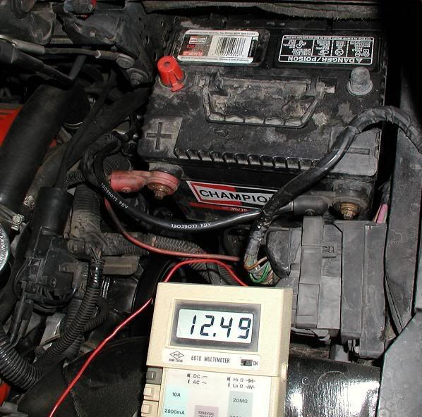
When you measure the voltage at the battery with the lights on, current is flowing. The voltage will drop slightly from 12.5 to around 12.3 volts, with the engine not running.
Now start the engine. A 12 volt car battery's idea charge voltage is 13.5 volts or greater. A reading near this shows that your regulator and alternator is working well. I like to see 14.7 volts myself. A good battery should be 13.5 or greater and quickly increase up to the 14's.

Polarity, meter hook-up: Correct voltmeter test lead hookup polarity is important. On some cars (not Fieros) a sensor calibration may occasionally shift from a positive reading to a negative reading. On 12-volt negative ground battery systems, always connect the voltmeter with the positive lead(red) to the voltage terminal being measured and the negative lead(black) to battery ground (-).
In most digital circuits, a positive signal voltage with no (+) sign will be displayed on the voltmeter for voltages above (0).
If you see a negative voltage (-) on the meter display, the component or sensor calibration may have changed or shifted to a negative reading.
Floating zero: Digital voltmeter display digits sometimes float around 0 from a small � to + voltage. This occurs when the meter is not connected to a circuit, (no signal) to the meter. Some meters stay right on zero without a signal.
Adding Some Power -
Hook up the voltmeter to a sensor signal wire. Then apply power to the circuit by turning on the ignition key. The display will show a steady voltage reading even if it is zero. A steady display indicates a definite voltage signal to the meter. For example, when measuring a computer ground circuit, the meter digits may float around zero. As you turn on the ignition key to flow a few milliamps in the sensor circuit, the meter floating will stop and stay steady indicating a signal is present.
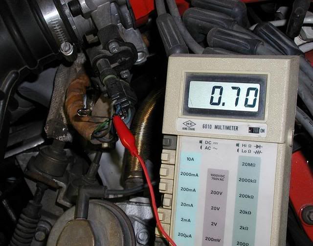
TPS ground connection. (bottom wire)

This tells you the backprobe is successful and the voltmeter connection has been made.
It is also a good way to check your ecm ground might be bad. If you get a few millivolts reading on the senser ground you might want to work on your grounds.
TPS output connection idle position. (middle wire)
TPS full throttle position. (middle wire, Reading 4.49volt)
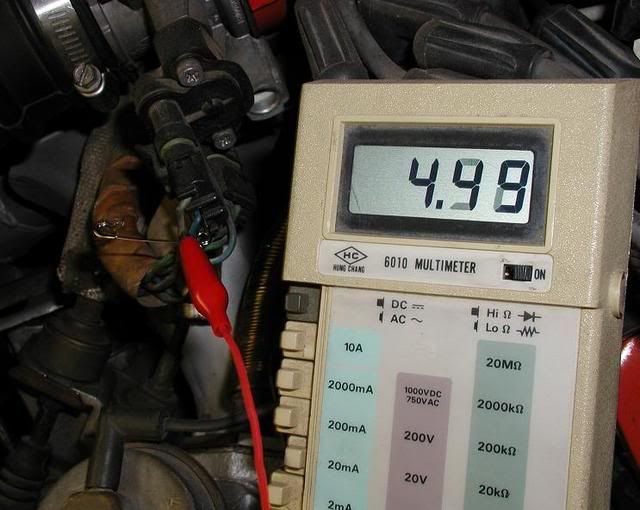
If you read the top wire that is the regulated reference voltage from the ecm used on all sensors. It should ALWAYS be 5 volts.
Key on: Note, after hooking up a voltmeter, it's OK to leave the key on with the engine off for testing computer systems.
Backprobing connectors: an easy way to backprobe, without damage, is to insert a heavy duty T-head pin into a connector parallel to the wire until it touches the connector terminal. (I'm using a safety pin since I dropped my T pin and can't find it) connect the voltmeter to the T pin with the red lead alligator clip. Connect the black lead to an engine or battery ground.
T Pins can be purchased at most sewing, fabric or hobby stores. Heavy duty T pins work better than small straight pins.
When backprobing, use only one T head pin at a time. If you use two T pins they may short to each other on two wire connectors. Watch out!
Piercing wires: Never (in my opinion) pierce wires with a pin. It looks bad, and it may provide an easy path into a computer circuit wire for corrosion. Corrosion can then creep up the wire to a computer or sensor connector. Eventually, the connection will fail (open up or build high resistance).
Resistance, hookup-
Isolate the circuit being measured by disconnecting the wire on both ends. Hookup the ohm meter. Select the highest scale, and measure resistance.
If the reading on the highest scale is zero, select the next lower scale to read resistance. Keep turning the function switch to lower range scales until the meter displays 1 or OL (out of range). Then, increase the function switch back up to the next higher scale to measure the resistance.
This method will provide the best accuracy. Reading to the nearest ohm is usually accurate enough for auto applications.
If you leave one end of the wire connected when measuring resistance, you may get feedback from the circuit resulting in an inaccurate ohm reading. Keep your fingers off the test lead connectors. If you touch the test lead connector, your body may become part of the circuit and change the resistance reading.
If the resistance reading is infinity (1 or OL) on the highest range (megohms) the circuit is open and no current will flow. On an auto-ranging digital ohmmeter, look for M ohms (megohms) on the right side of the meter display in an open circuit measurement.
Current, meter hookup:
Turn off all circuits in the vehicle. Move the test leads to the amp test lead jacks. Select the 10 or 15 amp scale at the function switch. When measuring current flow (amperes); disconnect the battery ground cable and install the ammeter in series. Re-connect the circuit by connection the red test lead to the battery cable end and the black lead to the battery negative post. Turn on the load (interior lights) and measure current flow
CAUTION, you must estimate how much current is flowing before hooking up the meter and selecting the correct current flow range. If you overload the ammeter the meter fuse may blow. (Yes they have a fuse inside) Never turn the key to the start position with the amp meter connected in the battery circuit.
A second caution: Most voltmeters state on the meter face the maximum fused current flow at the amp test jack.
If you blow the fuse on a fused meter, purchase only the specified replacement fuse. Most meters have a spare fuse(s) inside the case.
In the above example, a vehicle interior light circuit may flow around 1.5 amps.
Resistance Measurement
Resistance, what is it? Resistance is the opposition of current flow through a resistor such as a coolant temperature sensor. There is a small amount of resistance when current flows through the circuit wires, switches, grounds or connections.
If corrosion develops, fittings (bolts, connectors) become loose or wires fray, resistance increases abnormally increasing the resistance measurement. A switch, a connection, or the ground may build up resistance. Eventually, the circuit may open up at the point of high resistance. �Open circuit� means the circuit becomes disconnected. An analogy is a pipe flowing water. As the water pipe corrodes, the resistance to flow increases.
A Continuity Test
Let's conduct a continuity test on a brake stoplight switch. The term continuity usually means the circuit resistance is 0 (zero) when current is flowing. A continuity test is used to confirm the circuit is complete and will flow current when the switch is turned on. For example, when testing a stoplight circuit:
1 Disconnect the stoplight switch.
2 Switch the ohmmeter to continuity test or the lowest ohm scale.
3 Touch the test leads together to check the meter zero and the test leads.
4 A tone (if so equipped) should occur and/or ohms should read less than 0.3 (<three-tenths ohm).
5 Connect the test leads to the brake pedal switch terminals. The resistance will read OL or 1 (switch not on, pedal not depressed).
6 Press the brake. A tone will sound (if equipped), or the meter should read less than 0.3 ohm. If the display is 1 or OL with the pedal depressed, there is no continuity. The switch is off and not working. Check the terminals or see if the switch is sticking open.
Ignition Wire Resistance, Testing
This test checks for open circuits or high resistance in a carbon core secondary spark plug wire.
Disconnect the spark plug wire at both the distributor and spark plug ends. Twist the spark plug wire boots before removal.
1 Set the function switch to the highest resistance scale for this test. This scale is usually 20 megohms or more.
2 Connect the ohmmeter and check the meter zero.
3. Measure ohms. Twist and bend the spark plug wire and terminals while measuring the resistance to check for high resistance or an open circuit.
4. A good carbon core spark plug wire should read less than 20,000 ohms.
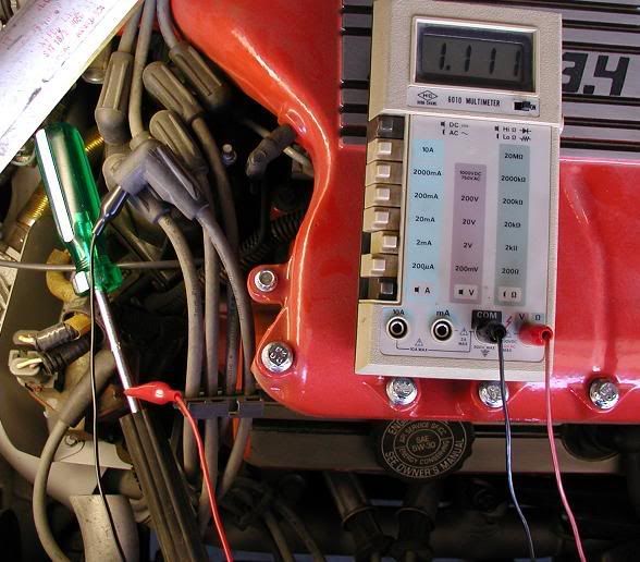
Old spark plug wires have higher resistance. It may have an open at the plug end. Open would read infinity on the highest resistance scale. If any carbon core spark plug wire up to three feet long is over 30,000 ohms replace it.
My #1 plug wire. (Reading 1.1K ohms, resistive wire?)
Distributor Cap and Rotor Resistance Test
This test checks for open circuits or high resistance in the distributor cap or rotor.
Remove the cap and rotor. Inspect for cracks and carbon tracks. Look for distributor cap center connector defects and electrode defects. Look for terminal corrosion.
If the cap is defective, replace it.
To test the cap electrodes' continuity, do the following:
1.Set the function switch to the lowest ohms scale.
2.Connect the test leads.
3.Test the meter and leads for zero.
4.Connect the test probes to opposite ends of the distributor cap terminal
5.Most rotor cap button resistance test are 0.1 of less.
6.Connect the test probes to opposite ends of the rotor contacts.
7.Rotor resistance should be 0.1 ohms or less.
Some rotors may have built-in resistance between the rotor center and the tip. Some have as much as 5000 ohms (5K). The Fiero rotor should not have any.
If there is an open or high resistance replace the rotor.
A Firebird rotor. (meter zero is .4 ohms)
Pick-up coil Resistance
This test confirms the pick-up coil resistance is within the manufacturer's specs.
1.Disconnect the pin-up coil.
2.Set the ohmmeter on the 2K restance scale.
3.Test the leads and meter for zero.
4.Connect the test lead probes to the pick-up coil leads. Wiggle the pick-up coil leads during testing to confirm the pick-up coil leads are not broken.
5.Record the resistance (ohms) (helpful to have the next time you check it for change)
Most electronic pick-up coils will measure between 500-1500 ohms.
If the ohm reading is outside the resistance range of the coil by more than +/- 10% replace the coil.
If suspect, measure the resistance in a hot engine and at room temperature. If the resistance chabnes by more than 10% replace it.
Check for short to ground by touching red test lead to distributor base. Leave the black lead connected to one coil terminal. The reading should be infinity (and beyond... sorry had to do that) on the highest scale.
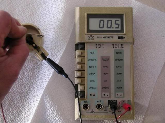
Coil Pack Resistance
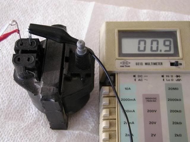
Disconnect and measure the coil primary resistance. It should be around 0.5 to 1.0 ohms. Account for the meter and test lead zero resistance. If meter zero is 0.4ohms (what mine zeros at) and the coil primary measurement is .9 ohms, the primary resistance is 0.5 ohms.
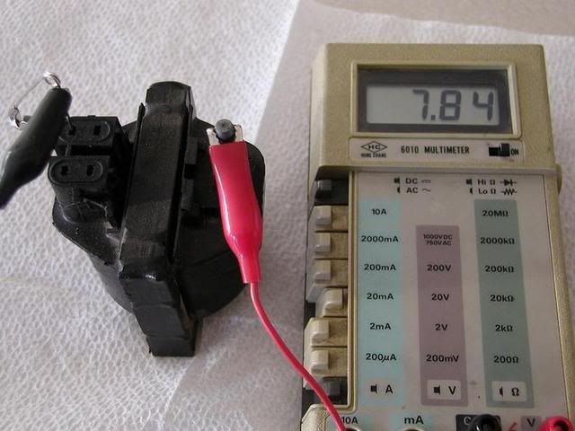
To measure the secondary resistance, disconnect the coil wire. Connect the test leads to the secondary coil tower and a primary connection. Read the secondary resistance starting on the highest range and working down to the most accurate reading.
Primary coil resistance.
Secondary winding. (Reading 7.84K ohms or 7840ohms)
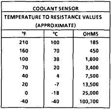
Coolant Sensor Resistance.
Coolant sensors are sensitive to coolant temperature changes. As the coolant temperature changes, the sensor's resistance value changes. Coolant sensors are usually called thermistors.
An NTC (negative temperature coefficient) thermistor resistance decreases as coolant temperature increases.
A PTC (positive temperature coefficient) thermistor increases as the coolant temperature increases.
(Just so happens NTC are easier to make and hence cheaper. Go figure that is what car manufacturers would use)
Most 1980 and later computer-controlled vehicles use NTC thermistors. (The 75-80 Cadillac port fuel injection systems actually use PTC thermistors for coolant and intake air sensor application.)
To measure the resistance of a coolant sensor:
1.Disconnect the coolant sensor.
2.Select the highest ohms range. Switch to lower resistance scale for accuracy.
3.Test the meter and leads for zero. (getting tired of hearing that yet).
4.Connect the test probes to the sensor terminals.
5.If the coolant is cold (around 70*F) compare the resistance to specifications ohms at 70*. Likewise, check the resistance at 180*F or 212*F.
6.If the sensor circuit is open replace the sensor.
7.Check for a short to ground by moving one test lead to the sensor body. The reading should be infinity on the highest scale.
What's next?....Part 3 More voltage measurements.
[This message has been edited by Dodgerunner (edited 04-22-2007).]


