So after alot of delays, we decided to start on the wiring this past weekend. Its really not as bad as we expected, but there are questions. we have a few plugs that were not sure about, and some wires that came out of the ECM that were not sure to keep or eliminate.
UNKOWN PLUGS:
do we need any of these, or any of the wires on them?
UNKOWN WIRES:
not really sure which of these we need to eliminate...
seems like these black wires are all connected and go everywhere?
and just some other pictures! if anything looks out of place or you can see something that needs to go, please let us know!
thats about it!
Blake
IP: Logged
02:30 PM
PFF
System Bot
darkhorizon Member
Posts: 12279 From: Flint Michigan Registered: Jan 2006
woo, now thats one lot of pictures. Its sorta tough to assume the identity of these, but I will try my best. Answers are below said picture.
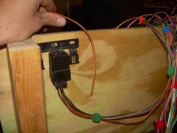
AC clutch turn on wire, needed if your using AC
Unknown body connector
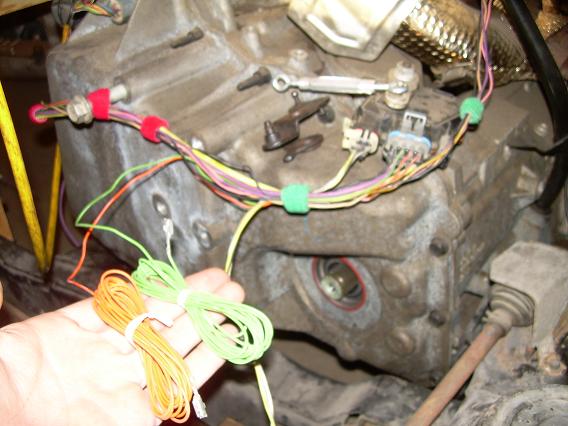
Trans connector or possibly ABS connector if there are twisted pair wires coming out of it. if it is the trans connector, most of those wires are for the pressure and shifting controls and go directly to the PCM. The range switch on the top of the gear selector controls starter enable, turns on backup lights, and tells the PCM what gear its in.
not going to eliminate much here, Most all of these are going to either the PCM, starter or backup lights as I said before.
Most all your blacks are grounds, with I dont think even one exception unless it has a white stripe (I think an injector line and a IAC line are black with a white stripe)
If you are low mounting the alternator, you dont need that big red wire running on top of the motor. And in no case will it ever need to be run inside the cab. It looks like your moving the c500 inside, which is fine, but I suggest leaving the "constant power" connection terminal in the stock location by the battery, it makes things a bit easier, and is not a huge eyesore.
dark - awesome, thanks! I left out some details i should probably include. its a 99 GTP motor going into an 86 2m4. we are not using a/c.
here we have a list of wires from the ECM that we dont know if we should remove:
Pressure Control Solenoid High Pressure Control Solenoid Low Transmission Fluid Pressure Switch B Transaxle Fluid Temp Sensor TCC PWM Solenoid Control Vehicle Speed Signal Output Class 2 Serial Data Transmission Fluid Pressure Switch C Normal/Performance Switch Input 5 Volt Reference B Serial Data (UART) Trans. Fluid Pressure Switch A Input
Sorry if some of this seem kind of basic, neither of us know much about wiring...
Blake
IP: Logged
07:50 PM
darkhorizon Member
Posts: 12279 From: Flint Michigan Registered: Jan 2006
dark - awesome, thanks! I left out some details i should probably include. its a 99 GTP motor going into an 86 2m4. we are not using a/c.
here we have a list of wires from the ECM that we dont know if we should remove:
Pressure Control Solenoid High Pressure Control Solenoid Low Transmission Fluid Pressure Switch B Transaxle Fluid Temp Sensor TCC PWM Solenoid Control Vehicle Speed Signal Output Class 2 Serial Data Transmission Fluid Pressure Switch C Normal/Performance Switch Input 5 Volt Reference B Serial Data (UART) Trans. Fluid Pressure Switch A Input
Sorry if some of this seem kind of basic, neither of us know much about wiring...
Blake
all of the trans related stuff goes to the gray round connector on top of the trans :
Pressure Control Solenoid High Pressure Control Solenoid Low Transmission Fluid Pressure Switch B Transaxle Fluid Temp Sensor TCC PWM Solenoid Control Transmission Fluid Pressure Switch C Trans. Fluid Pressure Switch A Input
the 5volt ref gets sent to most your sensors on the motor.
the performance goes to a "grounded switch" somewhere, or you can just ground it so its always performance shift.
serial is not used for anything.
VSS output gets the adapter circut put onto it. I think if you did your research you found that, if not I will dig it up.
This is just a spare CONSTANT power wire going somewhere, as long as the relay has constant power and you are not feeding anything else with that wire, you are fine
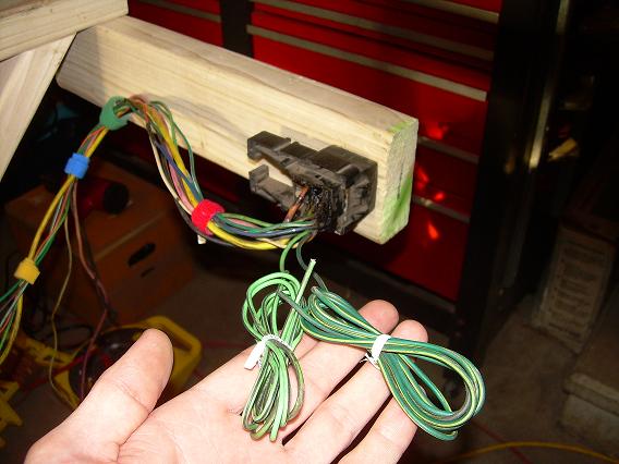
these two green wires from c500
Fan switch wires most likely or maybe a temp sensor wire, that goes to the green wire on the temp sensor.
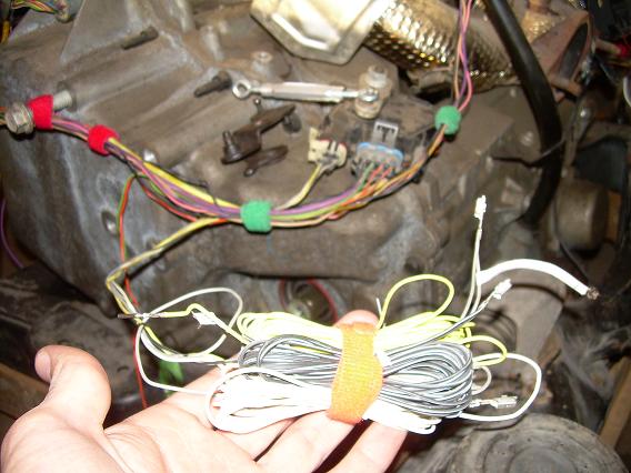
these all come from the tranny shift selector
some of which have ECM pins on it but some went to a junction block i believe
These do go to the pcm, they keep the same wire colors, but they are routed to the body on a stock harness. Just connect them to the right places on the PCM, and you should be ok there.
Blake[/QUOTE]
IP: Logged
02:42 PM
Khaos88GT Member
Posts: 329 From: Lake Charles, LA Registered: Sep 2007
interesting thread as im in the middle of my wiring. i like the wooden jig you designed, did yall measure the distance to the firewall from the engine with the engine mounted, like from the valve cover to the firewall because i would really like to know how far that is. it would help me out with my airing alot?
Dark- the wires comming off the tranny selector with ECM pins are no problem - just plug em back in. but what about the ones without ECM pins? i should be able to match them onto the ecm after i hunt them out on my diagrams?
i have seen alot of people quick to jump on you about stuff but your always the first person to help in my threads. thank you.
Khaos88GT - yes we did alot of measuring. the wooden jig should be very close to where the firewall will be. i dont have the measurements in front of me but i can get them to you, and if it would help i can take some more pictures of it.
IP: Logged
02:34 PM
Khaos88GT Member
Posts: 329 From: Lake Charles, LA Registered: Sep 2007
I'm good on pictures, thanks though, and by the looks of it you are too. LOL. Very Informative. Measurements are just fine if you can find them. Wiring looks great too!
Dark- the wires comming off the tranny selector with ECM pins are no problem - just plug em back in. but what about the ones without ECM pins? i should be able to match them onto the ecm after i hunt them out on my diagrams?
i have seen alot of people quick to jump on you about stuff but your always the first person to help in my threads. thank you.
Khaos88GT - yes we did alot of measuring. the wooden jig should be very close to where the firewall will be. i dont have the measurements in front of me but i can get them to you, and if it would help i can take some more pictures of it.
you should be able to find a friend for all of those wires on the pcm, otherwise dont worry about it. I think there is a pink power wire on one or 2 of those trans connectors... they get 12v switched.
Khaos88GT- from the top edge of the valve cover its about 7 1/2 inches, if your building the rails on the inside of the cradle, both of the side "extensions" are a foot.
-we have it all taken care of with just a few exceptions. we have a green wire coming from from the tranny that still doesnt have a home. -And the purple wire from the c203 - VSS low. the ecm slot for VSS low is already taken...
help is always appreciated, and thanks to those who have already helped.
blake
IP: Logged
12:23 PM
Khaos88GT Member
Posts: 329 From: Lake Charles, LA Registered: Sep 2007
pretty much you arent going to need any plugs that dont go onto the something on the motor except relay wires, a/c compressor wires, alternator wires and any wires that go to c500, c203, or data connector. i put my entire motor together compressor, alt, starter and all then plugged all connectors into one side, routed wires, then did the other side. pretty much just like fieroflyers thread. if you completely disassembled your harness then doing it this way will keep you train of though focused as far as knowing what to keep and what to throw away and also helps keep you from forgetting plugs. no this is not the only god-forsaken way to do it but im not going to bring other options into it as i understand what its like to be confused. just let me know if you have any more questions or refer to flyer's thread. im in no means a wiring guru like i said still in the middle of my own wiring but i have driven flyer and everyone else crazy with my research and asking a billions of questions that i can help you out on most stuff if you need it.
[This message has been edited by Khaos88GT (edited 05-12-2008).]
To keep anyone up to speed, the swap is about done but we are having problems with the fuel pump relay. Does anyone have a diagram that shows where all these wires go? Everything i have only shows 3 wires on the relay and i have 6 i believe. Would be much appreciated.
Blake
[This message has been edited by 85sliverGT (edited 07-19-2008).]
85SilverGt I wish I had an answer for you but here's a bump with my question attached.
So your running along wishing to remove all the pinouts on an 99 regal pcm and harness that you will get flashed to a 99 gtp. You look at the 99 gtp pinout and notice that clear 24 get's no use. However on your 99 regal harness clear 24 has a stinking pink wire in it. Do you A. Delete the stinking pink wire. (yank out and use for high end garage sound speaker system wiring) or B. apply 12 volts to the stinking pink wire. ??? Any clarification would be appreciated.
[This message has been edited by Bubbajuju (edited 07-20-2008).]
Bubbajuju- Im not sure i have your answer either. Do you have diagrams for the regal? What does it say the wire is? or just follow the wire, where does it go? I suppose it all depends on what the wire is supposed to be doing.
85sliverGT, I just got some wiring diagrams for the 99 regal- thanks to CowsPatoot. They have some informative info on the a/c workings. Maybe you already have them but here's a link. https://www.fiero.nl/forum/Forum2/HTML/093546.html As for my question I believe the answer will be "The PCM is now a 99 gtp, so wire it exactly like a 99gtp." So I think the pink clear 24 gets yanked. Have you read this one? https://www.fiero.nl/forum/Forum2/HTML/091320.html
Thanks, i have seen those. I checked this morning and ours is a 99 and we have no wire in pin 24.
Right now i have switched 12v jumping to the fuel pump so it will turn on with the key, but the car wont start. I tried plugging in a code reader and it errors out, so im pretty clueless right now what the problem could be.