Pennock's Fiero Forum
  Technical Discussion & Questions - Archive
  Stealth and 3000GT Dash install technical information (Page 2)

T H I S   I S   A N   A R C H I V E D   T O P I C
  

Email This Page to Someone! | Printable Version

This topic is 2 pages long:  1   2 
Previous Page | Next Page
Stealth and 3000GT Dash install technical information by ryan.hess
Started on: 08-29-2006 09:44 PM
Replies: 68
Last post by: ryan.hess on 05-17-2008 07:53 PM
ryan.hess
Member
Posts: 20784
From: Orlando, FL
Registered: Dec 2002


Feedback score: (1)
Leave feedback


Total ratings: 319
Rate this member

Report this Post09-10-2006 11:01 AM Click Here to See the Profile for ryan.hessSend a Private Message to ryan.hessDirect Link to This Post
Guess I gotta post pics for anybody to be interested anymore...


vrrrrroooooommmm

IP: Logged
Riceburner98
Member
Posts: 2179
From: Natick, Ma, USA
Registered: Apr 2002


Feedback score:    (10)
Leave feedback


Total ratings: 80
Rate this member

Report this Post09-10-2006 07:58 PM Click Here to See the Profile for Riceburner98Send a Private Message to Riceburner98Direct Link to This Post
LOL If my engine sees that RPM, it's BOOM, not Vrooom! Good work, that thing's pretty small! Did you etch the board or have it made? And when can I buy one? The tach signal from the 3800 ICM should be pretty clean, but how is the Fiero's? Would it be a problem with a bad tach filter? Just curious.. Good to see there's also still enough room for that row of LED displays that will replace the text at the bottom of the gauge...............

[This message has been edited by Riceburner98 (edited 09-10-2006).]

IP: Logged
ryan.hess
Member
Posts: 20784
From: Orlando, FL
Registered: Dec 2002


Feedback score: (1)
Leave feedback


Total ratings: 319
Rate this member

Report this Post09-10-2006 09:40 PM Click Here to See the Profile for ryan.hessSend a Private Message to ryan.hessDirect Link to This Post
Yeah, what are those square boxes on the bottom of the cluster?? Is that for some light indicators or something? Do any models have those working??

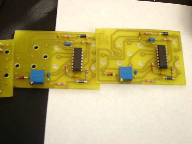
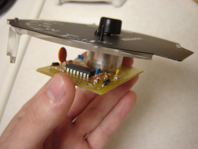
I etched the board myself. It would've cost 30x as much if I sent them out. The circuit I used mimicks the one the stock fiero tach uses. It will work just fine tapping into the primary of a coil, or a 5v square wave. There is some filtering for high frequency noise. I'm not sure exactly what the stock fiero filter does, but I imagine it is for the same reason. In otherwords, you shouldn't need a tach filter.

You can buy one now, but I won't have it assembled for about a week.

You'll need to swap out the threaded contacts from the old tach board, and the meter of course... I can make a post about what that involves, Denso made it real easy, the meter just pops off the board.

Oh, also just wanted to make the point that the components I chose will make this VERY temperature stable. You won't have to worry about drift unless you're on fire.

[This message has been edited by ryan.hess (edited 09-10-2006).]

IP: Logged
Sourmug
Member
Posts: 4538
From: Calgary, Alberta, Canada
Registered: Sep 2002


Feedback score:    (29)
Leave feedback


Total ratings: 144
Rate this member

Report this Post09-14-2006 08:44 PM Click Here to See the Profile for SourmugSend a Private Message to SourmugDirect Link to This Post
Ryan:

The board looks great! Are you planning on doing a "How To" for those of us who are technically disinclined in this area?

Thanks
Nolan
IP: Logged
ryan.hess
Member
Posts: 20784
From: Orlando, FL
Registered: Dec 2002


Feedback score: (1)
Leave feedback


Total ratings: 319
Rate this member

Report this Post09-14-2006 09:24 PM Click Here to See the Profile for ryan.hessSend a Private Message to ryan.hessDirect Link to This Post
"How to" from remove tachometer, to drive away?

I will. I redesigned the board to get rid of that evil jumper wire. It was close, but I did it. So I'll put together everything, and then show you what you need to do to transfer the parts from the mitsu tach to the "super cool fiero tach"

If you guys wanted to wash your hands of everything, I could even do the work for you... Send me your speedo, and $50, and I'll install the board and calibrate it for I4/V6/V8 and send it back. I can't guarantee that it will be 100% accurate once it goes into your car, but I can walk you through the process of adjusting it if it's off. It should be within 1-2% though.

Otherwise, I will have the assembled boards ready to ship in the next few days... $25 shipped, and you can follow the instructions here on how to install and calibrate it.

IP: Logged
Riceburner98
Member
Posts: 2179
From: Natick, Ma, USA
Registered: Apr 2002


Feedback score:    (10)
Leave feedback


Total ratings: 80
Rate this member

Report this Post09-14-2006 10:11 PM Click Here to See the Profile for Riceburner98Send a Private Message to Riceburner98Direct Link to This Post
 
quote
Originally posted by ryan.hess:

Yeah, what are those square boxes on the bottom of the cluster?? Is that for some light indicators or something? Do any models have those working??


Now that is a good question... I kind of thought they looked like a "digital" tachometer, since they're kind of "ramp-shaped" if I remember right, but why would they do that with light bulbs? That wouldn't react very fast.. My plan was to cut some remote mounted digital gauge displays into the analog faces, under the needles. That way you have the visual sweep of the analog gauge, combined with the accuracy of digital. I did it way back (lol) in college on my '94 Eagle Summit (Mitsu. something or other..) and it came out great, looked OEM. Wanted to do it ever since, but just haven't had the time. Now that I have the AeroForce digital computer scan tool / gauge, I want to cut that into the 3kGT cluster as well - possibly taking over the position of a couple of the center ovals of idiot lights.. I think it would look awesome there, just remote mount the screen and buttons... That and a working tach. Of course, the car has to actually *run* first, now doesn't it? But sign me up for one of the boards! It can join the stock-pile of parts that are waiting for the car to be done.
IP: Logged
Sourmug
Member
Posts: 4538
From: Calgary, Alberta, Canada
Registered: Sep 2002


Feedback score:    (29)
Leave feedback


Total ratings: 144
Rate this member

Report this Post09-20-2006 08:21 PM Click Here to See the Profile for SourmugSend a Private Message to SourmugDirect Link to This Post
Hi:

Any updates, progress?

Thanks
Nolan
IP: Logged
ryan.hess
Member
Posts: 20784
From: Orlando, FL
Registered: Dec 2002


Feedback score: (1)
Leave feedback


Total ratings: 319
Rate this member

Report this Post09-20-2006 10:17 PM Click Here to See the Profile for ryan.hessSend a Private Message to ryan.hessDirect Link to This Post
I'll have an update this weekend.
IP: Logged
ryan.hess
Member
Posts: 20784
From: Orlando, FL
Registered: Dec 2002


Feedback score: (1)
Leave feedback


Total ratings: 319
Rate this member

Report this Post09-23-2006 05:04 PM Click Here to See the Profile for ryan.hessSend a Private Message to ryan.hessDirect Link to This Post
Okay, I have 3 boards... If you're interested, let me know and I'll mail one to you on monday for $25.


Next I'm going to post the steps necessary to install/use it.
IP: Logged
ryan.hess
Member
Posts: 20784
From: Orlando, FL
Registered: Dec 2002


Feedback score: (1)
Leave feedback


Total ratings: 319
Rate this member

Report this Post09-23-2006 05:25 PM Click Here to See the Profile for ryan.hessSend a Private Message to ryan.hessDirect Link to This Post

ryan.hess

20784 posts
Member since Dec 2002
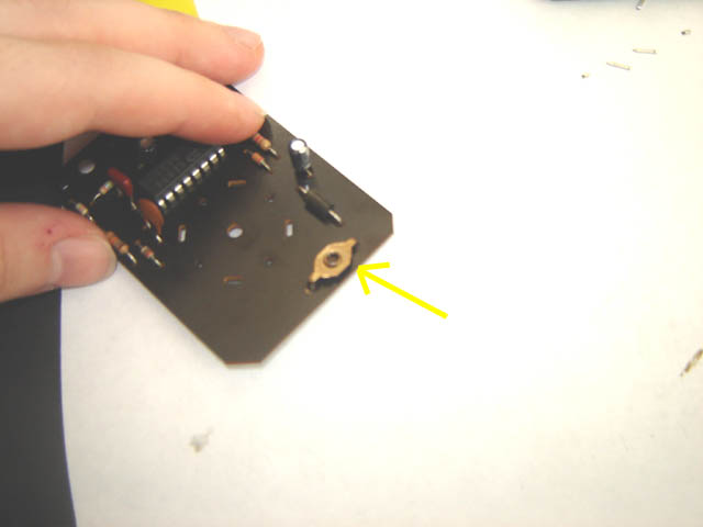
First, you need to take apart your stock board. The first step is to remove the meter assembly.

Bend the tangs holding the meter to the board back. (sorry for the blurryness of these next pics...)


Then the meter assembly will just pull right off. You will be left with 4 pins sticking out of the board. You will need to take some pliers, heat up the solder on the back, and slip them out.

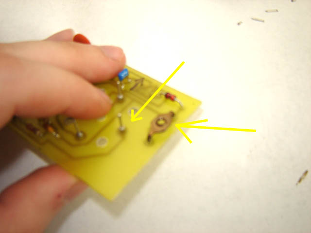
Next, you need to remove the 3 threaded inserts.


These are a bit trickier, since the pins are bent back a bit after they're on the board. Use a small flat tip screwdriver, and wedge it between the board and the insert, and heat one of the pins with a soldering iron. Carefully pry one side up, then the other. You'll have to bend the pins back so they'll fit back in the new board.

Next, install the inserts, and solder them in. Take the 4 pins you removed earlier, and install them back into the meter assembly. The long ends go into the meter, the short ends fit back into the PCB. Then, install the meter assembly onto the board. You might have to wiggle it a bit to get all the pins to line up. There will be an arrow indicating "up" to guide you. Then solder the pins, and bend the tangs back to secure it.

This here shows the pins and the inserts assembled, but no meter. Make sure you install the pins into the meter before you solder them. Otherwise you'll never get them to fit together.


So, now it's assembled, right?

Now you just have to install everything into your car, and figure out how to calibrate it. The pots I used have 25 or so turns from lock to lock. This gives you the full range for 4 cylinder and v8 adjustment. The trick is, how are you guys going to calibrate them? I guess you could install it, and check it at some rpm with a scantool or ALDL reader... That's not the best way to do it...

Do you guys have a volt meter that can measure frequency? If so, I could write you a program to calibrate your meters.......

[This message has been edited by ryan.hess (edited 09-23-2006).]

IP: Logged
Sourmug
Member
Posts: 4538
From: Calgary, Alberta, Canada
Registered: Sep 2002


Feedback score:    (29)
Leave feedback


Total ratings: 144
Rate this member

Report this Post09-23-2006 06:40 PM Click Here to See the Profile for SourmugSend a Private Message to SourmugDirect Link to This Post
Paypal?

Thanks
Nolan
IP: Logged
PFF
System Bot
ryan.hess
Member
Posts: 20784
From: Orlando, FL
Registered: Dec 2002


Feedback score: (1)
Leave feedback


Total ratings: 319
Rate this member

Report this Post09-23-2006 07:15 PM Click Here to See the Profile for ryan.hessSend a Private Message to ryan.hessDirect Link to This Post
I do... can ship monday..

Ryan.h (at) excite.com

Do you have a frequency counter on your meter? Or will you give the idle calibration a shot? If you can hold the rpm at 3000, it would be better, but you would need to block the throttle or something so it doesn't change.
IP: Logged
Fiero1Fan
Member
Posts: 4364
From: Brachttal, Germany
Registered: Sep 2005


Feedback score:    (19)
Leave feedback


Total ratings: 100
Rate this member

Report this Post09-23-2006 09:00 PM Click Here to See the Profile for Fiero1FanClick Here to visit Fiero1Fan's HomePageSend a Private Message to Fiero1FanDirect Link to This Post
 
quote
Originally posted by ryan.hess:

I do... can ship monday..

Ryan.h (at) excite.com

Do you have a frequency counter on your meter? Or will you give the idle calibration a shot? If you can hold the rpm at 3000, it would be better, but you would need to block the throttle or something so it doesn't change.


PM and PayPal sent.

Thanks for this and all your work is highly appreciated!!

IP: Logged
Sourmug
Member
Posts: 4538
From: Calgary, Alberta, Canada
Registered: Sep 2002


Feedback score:    (29)
Leave feedback


Total ratings: 144
Rate this member

Report this Post09-23-2006 09:15 PM Click Here to See the Profile for SourmugSend a Private Message to SourmugDirect Link to This Post
MY meter may have a frequency counter but if not a buddy of mine has one with it. If you could wriet a program that would be great, could you provide instructions on how to implement it too?

PayPal sent!

Thanks a ton for doing this!

Nolan
IP: Logged
ryan.hess
Member
Posts: 20784
From: Orlando, FL
Registered: Dec 2002


Feedback score: (1)
Leave feedback


Total ratings: 319
Rate this member

Report this Post09-23-2006 09:43 PM Click Here to See the Profile for ryan.hessSend a Private Message to ryan.hessDirect Link to This Post
Okay, will do.

Yours will go out monday as well.

IP: Logged
Fiero1Fan
Member
Posts: 4364
From: Brachttal, Germany
Registered: Sep 2005


Feedback score:    (19)
Leave feedback


Total ratings: 100
Rate this member

Report this Post09-23-2006 10:08 PM Click Here to See the Profile for Fiero1FanClick Here to visit Fiero1Fan's HomePageSend a Private Message to Fiero1FanDirect Link to This Post
Hah! Procured another part for my dash swap! Things are looking up!!

Now I just need to keep stealing ideas from Sourmug, 4.9 PFI, riceburner, ryan.h, etc!!

[This message has been edited by Fiero1Fan (edited 09-23-2006).]

IP: Logged
Sourmug
Member
Posts: 4538
From: Calgary, Alberta, Canada
Registered: Sep 2002


Feedback score:    (29)
Leave feedback


Total ratings: 144
Rate this member

Report this Post09-24-2006 12:52 AM Click Here to See the Profile for SourmugSend a Private Message to SourmugDirect Link to This Post
Copying something its the highest form of flattery

Nolan
IP: Logged
Fiero1Fan
Member
Posts: 4364
From: Brachttal, Germany
Registered: Sep 2005


Feedback score:    (19)
Leave feedback


Total ratings: 100
Rate this member

Report this Post09-26-2006 01:00 AM Click Here to See the Profile for Fiero1FanClick Here to visit Fiero1Fan's HomePageSend a Private Message to Fiero1FanDirect Link to This Post
Ryan, PM sent.
IP: Logged
Sourmug
Member
Posts: 4538
From: Calgary, Alberta, Canada
Registered: Sep 2002


Feedback score:    (29)
Leave feedback


Total ratings: 144
Rate this member

Report this Post10-06-2006 06:49 PM Click Here to See the Profile for SourmugSend a Private Message to SourmugDirect Link to This Post
Ryan:

I received the board today and it looks great. I hope you don't mind but I would like to pick your brain once I get to the point of doing the instrumentation and wiring.

Thanks
Nolan
IP: Logged
ryan.hess
Member
Posts: 20784
From: Orlando, FL
Registered: Dec 2002


Feedback score: (1)
Leave feedback


Total ratings: 319
Rate this member

Report this Post10-17-2006 04:05 PM Click Here to See the Profile for ryan.hessSend a Private Message to ryan.hessDirect Link to This Post
I promised you software... but I have something even better....

Now you DON'T need any frequency counter... just this:

http://www.daqarta.com/dgdown.htm

Download the software, and purchase a 1/8" mono plug (connector) from radioshack. (part # 274-287) You will need to solder 2 wires to it, one for the signal (to the "tip" connector) and one for ground (to the "base" connector) They have a cable with a 1/8" end and aligator clips on the other, but I haven't been able to find it online. Tie the signal to the tach input, and the ground to the tach ground. Apply 12V power to the tach board.

Then, turn on the generator, and select the frequency you need to represent redline on your engine (this is where you *need* accuracy). Next, adjust the potentiometer until the needle reading is your redline. Done. Easy huh?

***So how do you select the redline frequency?
Calculate it as follows:

Take your redline RPM (e.g. 6000rpm)
divide by 60... ( = 100)
divide by 2 ( = 50)
multiply by the number of cylinders (e.g. 8 = 400)

That's the frequency of that particular RPM. 400Hz. Just enter that number into the signal generator, and dial in the tach. Formula works for distributor and DIS systems.

*Disclaimer* I'm not responsible if you blow up your computer

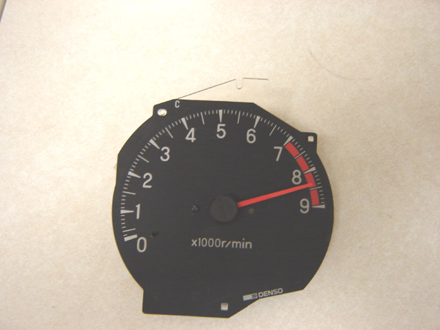
For reference, in this pic, you can see my sharpee marks:


On the left is ground (-). On the right top is positive (+). On the right bottom is tach signal in.

[This message has been edited by ryan.hess (edited 10-17-2006).]

IP: Logged
ryan.hess
Member
Posts: 20784
From: Orlando, FL
Registered: Dec 2002


Feedback score: (1)
Leave feedback


Total ratings: 319
Rate this member

Report this Post10-21-2006 10:29 AM Click Here to See the Profile for ryan.hessSend a Private Message to ryan.hessDirect Link to This Post
Bump!
IP: Logged
PFF
System Bot
Riceburner98
Member
Posts: 2179
From: Natick, Ma, USA
Registered: Apr 2002


Feedback score:    (10)
Leave feedback


Total ratings: 80
Rate this member

Report this Post10-21-2006 11:41 AM Click Here to See the Profile for Riceburner98Send a Private Message to Riceburner98Direct Link to This Post
How easily I forget about things... Still have some left? Looks like that program makes it nice and easy to set up too, awesome!

------------------
Bob Williams
Working on the next 3800 swap.. Missing the one that worked!

IP: Logged
Sourmug
Member
Posts: 4538
From: Calgary, Alberta, Canada
Registered: Sep 2002


Feedback score:    (29)
Leave feedback


Total ratings: 144
Rate this member

Report this Post10-21-2006 12:27 PM Click Here to See the Profile for SourmugSend a Private Message to SourmugDirect Link to This Post
Wow! that sure looks like it makes it a piece of cake! Thanks for the link.

Nolan
IP: Logged
ryan.hess
Member
Posts: 20784
From: Orlando, FL
Registered: Dec 2002


Feedback score: (1)
Leave feedback


Total ratings: 319
Rate this member

Report this Post10-21-2006 12:31 PM Click Here to See the Profile for ryan.hessSend a Private Message to ryan.hessDirect Link to This Post
 
quote
Originally posted by Riceburner98:
How easily I forget about things... Still have some left? Looks like that program makes it nice and easy to set up too, awesome!


Yep, I have one premade, and parts for more...
IP: Logged
Riceburner98
Member
Posts: 2179
From: Natick, Ma, USA
Registered: Apr 2002


Feedback score:    (10)
Leave feedback


Total ratings: 80
Rate this member

Report this Post10-21-2006 01:26 PM Click Here to See the Profile for Riceburner98Send a Private Message to Riceburner98Direct Link to This Post
Paypal sent!
IP: Logged
RCR
Member
Posts: 4397
From: Shelby Twp Mi
Registered: Sep 2002


Feedback score:    (7)
Leave feedback


Total ratings: 102
Rate this member

Report this Post02-05-2007 09:08 AM Click Here to See the Profile for RCRSend a Private Message to RCRDirect Link to This Post
Bump, because Ryan's stuff is cool.
IP: Logged
Sourmug
Member
Posts: 4538
From: Calgary, Alberta, Canada
Registered: Sep 2002


Feedback score:    (29)
Leave feedback


Total ratings: 144
Rate this member

Report this Post05-16-2007 11:48 PM Click Here to See the Profile for SourmugSend a Private Message to SourmugDirect Link to This Post
 
quote
Originally posted by ryan.hess:

Looking at the rear of the speedometer, there are 4 terminal screws. Left top is the signal input, left bottom is +12, right bottom is ground. I have no idea what the 4th one is for, which was throwing me off. Here is data on the signals used:


Tach:

RPM Frequency
1000 35.3Hz
2000 82.4Hz
3000 130.4Hz
4000 178.2Hz
5000 223.7Hz
6000 270Hz
7000 322Hz
8000 372Hz
9000 420Hz

99.99% correlation, RPM = 20.803(Hz)+298

For the Speedo:

MPH Frequency
40 39.5Hz
60 62.1Hz
80 84.0Hz
100 106Hz
120 129.4Hz
180 199Hz

99.99% correlation, MPH=0.878(Hz) + 5.92


I believe I have found the charge pump circuitry, so the tach can be recalibrated for I4 or "true" V6 or V8... The stock v6 must put out some wierd signal, like 2.5 pulses/rev or something.


Ryan:

How do I go about callibrating the speedo using your data above?

Thanks
Nolan
IP: Logged
fierogt455
Member
Posts: 282
From: Goldsboro, NC
Registered: Jun 2004


Feedback score:    (7)
Leave feedback

Rate this member

Report this Post10-19-2007 10:29 AM Click Here to See the Profile for fierogt455Send a Private Message to fierogt455Direct Link to This Post
Ryan,

Do you have any boards left?


Freeman
IP: Logged
ryan.hess
Member
Posts: 20784
From: Orlando, FL
Registered: Dec 2002


Feedback score: (1)
Leave feedback


Total ratings: 319
Rate this member

Report this Post05-17-2008 07:53 PM Click Here to See the Profile for ryan.hessSend a Private Message to ryan.hessDirect Link to This Post
Well, it's been a while, but people have been asking for it. So I am going to dig up what I have and post the information here.

IP: Logged
Previous Page | Next Page

This topic is 2 pages long:  1   2 


All times are ET (US)

T H I S   I S   A N   A R C H I V E D   T O P I C
  

Contact Us | Back To Main Page

Advertizing on PFF | Fiero Parts Vendors
PFF Merchandise | Fiero Gallery | Ogre's Cave
Real-Time Chat | Fiero Related Auctions on eBay


Copyright (c) 1999, C. Pennock