| | | quote | Originally posted by randye:
Not sure I'm following you Marvin.
...
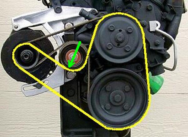
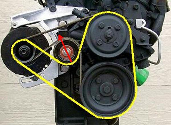
Movining the belt to the opposite side of the pulley, (shown in yellow), moves the load angle on the alternate routing as shown by the red arrow.
|
|
You are correct concerning the load angles on the idler pulley, but it's the load
magnitudes that are different. The bearing load on any pulley can be determined from
F = (Ta + Tb) * sin (alpha / 2)), where
F is the bearing load,
Ta and
Tb are the belt tensions (static + dynamic) on each side of the pulley, and
alpha is the total belt wrap angle around the pulley. It is important to note that
Ta =
Tb for an idler pulley, but they are unequal when a pulley is driving a load.
For the sake of simplicity, I'll use your picture and lets assume a "perfect" situation with low (~0) static belt tension, zero slippage on any pulley, and negligible belt stretch. When the engine is running, both the water pump and alternator present loads that require belt tension to turn them, and thus both present a dynamic tension load on the belt (i.e.
Ta !=
Tb). Let
T1 = the belt tension between the crankshaft pulley and the water pump pulley,
T2 = the belt tension between the water pump pulley and the alternator pulley, and
T3 = the belt tension between the alternator pulley and the crankshaft pulley.
T1 has to be high enough to turn
both the water pump and the alternator, while
T2 only has to be high enough to turn just the alternator, and
T3 will just equal static belt tension and doesn't have to carry any dynamic tension at all. Note that when the engine is stopped
T1 =
T2 =
T3, and that when it's running
T1 >
T2 >
T3.
With Rodney's belt path, all the idler sees is
T3, which is just the static belt tension. But with your path, the idler sees
T2, which the sum of the static belt tension
plus the tension required to turn the alternator, which is always going to be greater than
T3 alone. Q.E.D.
I hope this makes things a little clearer.
[This message has been edited by Marvin McInnis (edited 12-16-2007).]