Pennock's Fiero Forum
  Technical Discussion & Questions - Archive
  c2 connector location

T H I S   I S   A N   A R C H I V E D   T O P I C
  

Email This Page to Someone! | Printable Version


c2 connector location by ss85fiero
Started on: 10-03-2007 09:04 PM
Replies: 7
Last post by: Hudini on 10-06-2007 01:41 AM
ss85fiero
Member
Posts: 385
From: jacksonville florida usa
Registered: May 2006


Feedback score: (2)
Leave feedback

Rate this member

Report this Post10-03-2007 09:04 PM Click Here to See the Profile for ss85fieroSend a Private Message to ss85fieroDirect Link to This Post
I am trying to finish up my 4.9 project on my 87gt, and need to know where on the back of the instrument panel the c2 connector is, as there is three connectors on it, and also need to know which wires i need. What i am tryng to accomplish is to get the factory temp gauge to work. I temporarily have a mechanical temp gauge hooked up, but dont want any extra gauges inside car.

[This message has been edited by ss85fiero (edited 10-03-2007).]

IP: Logged
PFF
System Bot
IFLYR22
Member
Posts: 1775
From: Tucson, AZ.
Registered: May 2007


Feedback score: N/A
Leave feedback

Rate this member

Report this Post10-03-2007 09:39 PM Click Here to See the Profile for IFLYR22Send a Private Message to IFLYR22Direct Link to This Post
i believe your looking for the left hand side back of the instrument cluster, the black connector with 12 pins/connectors.
IP: Logged
Hudini
Member
Posts: 9030
From: Tennessee
Registered: Feb 2006


Feedback score: N/A
Leave feedback


Total ratings: 165
Rate this member

Report this Post10-04-2007 12:52 AM Click Here to See the Profile for HudiniSend a Private Message to HudiniDirect Link to This Post
Right about here:
IP: Logged
ss85fiero
Member
Posts: 385
From: jacksonville florida usa
Registered: May 2006


Feedback score: (2)
Leave feedback

Rate this member

Report this Post10-04-2007 06:39 PM Click Here to See the Profile for ss85fieroSend a Private Message to ss85fieroDirect Link to This Post
Thanks for the diagram Hudini, but i am now a bit puzzled as i see that there is a wire on the c2 and the c3 for the temp gauge\indicator. Which do i use?

[This message has been edited by ss85fiero (edited 10-04-2007).]

IP: Logged
ss85fiero
Member
Posts: 385
From: jacksonville florida usa
Registered: May 2006


Feedback score: (2)
Leave feedback

Rate this member

Report this Post10-04-2007 10:39 PM Click Here to See the Profile for ss85fieroSend a Private Message to ss85fieroDirect Link to This Post

ss85fiero

385 posts
Member since May 2006
anyone have an answer?

------------------
87 fiero gt 4.9
99 trans am ls1

IP: Logged
Hudini
Member
Posts: 9030
From: Tennessee
Registered: Feb 2006


Feedback score: N/A
Leave feedback


Total ratings: 165
Rate this member

Report this Post10-05-2007 01:39 AM Click Here to See the Profile for HudiniSend a Private Message to HudiniDirect Link to This Post
Coolant temp indicator = overheat light. Gauge = gauge. These are the 2 wires you switch around to fix the "pegging temp gauge" needle. I will look for the exact instructions on doing this if you are interested.
IP: Logged
ss85fiero
Member
Posts: 385
From: jacksonville florida usa
Registered: May 2006


Feedback score: (2)
Leave feedback

Rate this member

Report this Post10-05-2007 09:01 PM Click Here to See the Profile for ss85fieroSend a Private Message to ss85fieroDirect Link to This Post
Any info would be appreciated hudini. I am trying to figure out what two wires to hook up to the temp sensor that will make the gauge work. I no longer have an ecm in the vehicle due to the fact that the 4.9 i installed is carbureted, and the original wiring harness was a bit hacked up from a previous owner, so therefore, i am having to run wires from dash to the sensor.
IP: Logged
Hudini
Member
Posts: 9030
From: Tennessee
Registered: Feb 2006


Feedback score: N/A
Leave feedback


Total ratings: 165
Rate this member

Report this Post10-06-2007 01:41 AM Click Here to See the Profile for HudiniSend a Private Message to HudiniDirect Link to This Post
Ok, you are using a sensor specific to the 4.9 or is it the same Fiero sensor?

The Fiero actually only uses one wire to run the gauge and one wire to light the overheat light. The ground is through the sensor itself which is why you do not use sealant on the sensor threads.

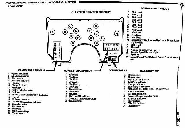
I would hook one wire to pin 13 on the C3 connector and run it out to the engine. Then another wire to pin 11 on the C2 connector and run it out to the engine. Then simply hook the wires to the 2 pins on the sensor. You have a 50/50 chance of getting the wires right the first time. If the gauge does not move when the engine is warm then swap the wires at the sensor.

To test the gauge you put a 1365 ohm resistor on the gauge wire and see if the gauge reads 100*F. Then put a 55 ohm resistor on the gauge wire and it should read 260*F. If it's off then pop off the needle and put it where it should be. A little pressure goes a long way.

If you need it the 1986 Factory Service Manual is available here: http://spad.sytes.net/fiero/manuals/
Page 972 shows the wiring diagram for the IP cluster. It also shows why the pegging temp gauge happens as the bulb test feature is wired through the gauge instead of the overheat light like it should.
IP: Logged


All times are ET (US)

T H I S   I S   A N   A R C H I V E D   T O P I C
  

Contact Us | Back To Main Page

Advertizing on PFF | Fiero Parts Vendors
PFF Merchandise | Fiero Gallery
Real-Time Chat | Fiero Related Auctions on eBay


Copyright (c) 1999, C. Pennock