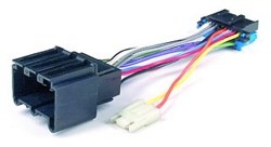
Table 1: Low Frequency Audio Amplifier
Table 3: Radio C1
Table 4: Radio C2
Table 5: Radio C3
Low Frequency Audio Amplifier
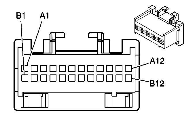
Connector Part Information
12110088
24 Way F Micro-Pack 100 Series (GRY)
Pin
Wire Color
Circuit No.
Function
A1
TAN
201
Speaker Feed-Left Front +
A2
LT GRN
200
Speaker Feed-Right Front +
A3
BRN
199
Speaker Feed-Left Rear +
A4
DK BLU
46
Speaker Feed-Right Rear +
A5-A8
--
--
Not Used
A9
BLK/ WHT
351
Ground
A10-A11
--
--
Not Used
A12
ORN
640
Fused Battery Feed
B1
GRY
118
Speaker Return-Left Front
B2
DK GRN
117
Speaker Return-Right Front -
B3
YEL
116
Speaker Return-Left Rear -
B4
LT BLU
115
Speaker Return-Right Rear
B5-B8
--
--
Not Used
B9
DK BLU/WHT
346
Subwoofer Speaker Feed-Left Rear +
B10
LT GRN/BLK
1794
Subwoofer Speaker Feed-Left Rear -
B11
DK GRN
1795
Subwoofer Speaker Feed-Right Rear +
B12
LT BLU/BLK
315
Subwoofer Speaker Return-Right -
Radio C1
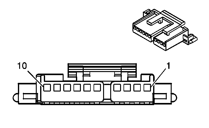
Connector Part Information
12047531
10 Way F Micro-Pack 100 Series (BLK)
Pin
Wire Color
Circuit No.
Function
1
GRY
118
Speaker Return-Left Front
2
TAN
201
Speaker Feed-Left Front +
3
DK GRN
117
Speaker Return-Right Front
4
LT GRN
200
Speaker Feed-Right Front +
5
BLK/ WHT
351
Ground-Clean
6
GRY/BLK
308
Park Lamp Switch Signal-Park-Lamps On
7
BRN/ WHT
230
Radio VF Dimmer Feed
8
DK GRN
145
Radio On Output
9
YEL
43
Fused Retained Accessory Power (RAP) Feed
10
ORN
640
Fused Battery Feed
Radio C2

Connector Part Information
12065785
10 Way F Micro-Pack 100 Series (GRY)
Pin
Wire Color
Circuit No.
Function
11-13
--
--
Not Used
14
DK BLU
1796
Steering Wheel Control Input
15
DK GRN
835
Entertainment and Comfort (E&C) Serial Data Communication
16
--
--
Not Used
17
LT BLU
115
Speaker Return-Right Rear -
18
DK BLU
46
Speaker Feed-Right Rear +
19
YEL
116
Speaker Return-Left Rear -
20
BRN
199
Speaker Feed-Left Rear +
Radio C3
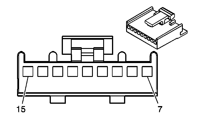
Connector Part Information
12064980
9 Way F Micro-Pack 100 Series (BLK)
Pin
Wire Color
Circuit No.
Function
7-9
--
--
Not Used
10
LT GRN
512
CD Right Signal
11
TAN
511
CD Left Signal
12
DK GRN
1947
CD Audio Common
13-15
--
--
Not Used
--------------------------------------------------------------------------------
Document ID# 303939
1998 Pontiac Grand Prix
.
.
.

AM-FM Stereo, Seek/Scan, Clock, Compact Disc, Equalizer (UP3)
Radio/Audio System Circuit Description
Radio
The radio receives battery voltage at all times on circuit 640 through the RADIO BATT fuse in order to keep the clock and preset memory alive when the ignition is in the OFF position. The radio is grounded through circuit 351. When the ignition is in the ACCY or RUN position:
Voltage is applied to circuit 43 through the RADIO fuse to enable the radio operation
The vacuum florescent (VF) display illuminates to display the time or radio frequency setting with the ignition switch
Compact Disc (CD) and Cassette Player
The CD or cassette player, if equipped is part of the radio unit. When operating, the same power required by the radio is necessary for the tape or CD player operation.
Low Frequency Audio Amplifier
The amplifier receives battery voltage at all times through circuit 640. The amplifier is grounded through circuit 351.
YOU NEED AN AMP TO HEAR SOUND OTHER THAN VERY LOW SOUND.
The AMP is list as under the I/P
This Radio has an Antenna module also. It is an AMP also. You may not get reception without it.
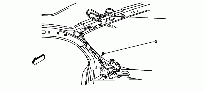
(1) Radio Antenna Module
(2) Rear Window Defogger Grid (C1) Connector


 But thank you for the link! I'm printing it off right now and will see how much damage I can do with that! I'll have to stop my Circuit City and pick up the adapter for the antenna...


