on searches in the archives I keep running into fancy shiny strut tower braces. Are these maily used for show or do they ad torsional stiffnes? Could the same effect not be acheaves by bracing the rear engine fire wall by welding a square ended bar towards the top?
Just looking at it....that part is the stiffest part of the chassis. It is torsional rigidity that makes a differance. That is....front twisting in one direction, and rear in the other. A floppy chassis makes independent syspension......less independent. It make fore-aft roll stiffness adjustments less meaningfull.
At some point, as syspentin becomes more and more acurate, tiny changes due to longitudinal twisting make minute adustments impossable. We just don't have a syspension that is that refined.
Of course....it you cut the top off........our crude syspention becomes WAY better the a fexable flyer it's attached to. The whole package becomes floppy and unfun.
You really don't need to worry...unless you cut the top off.
IP: Logged
02:06 PM
86_IRM_TURBO Member
Posts: 487 From: Commerce Township, MI, USA Registered: Dec 2006
If you look at many modern cars with the tops chopped you'll see Vee braces and X braces that attatch to the structure and help mostly with the torsional stiffness. The G-6, SLK, and BMW's all use these baces. Even the Z4 Coupe has them. The are fairly light weight and very effective. They can effect the torsion mode by 2-4 Hz. (top down) Good luck with your Targa project!
IP: Logged
11:15 PM
Dec 30th, 2006
fiero-iwan Member
Posts: 352 From: Eindhoven,Netherlands,Europe Registered: Mar 2003
I was not planning on taking of the roof or even making a targa, I just want to stiffen the chassis for better suspension performance and more predictable handling etc. I will be driving this fiero on the Ring in Germany, which as you may know is a high-speed track.
"2-4 Hz top down", excuse my ignorance but would you care to explain how that works and what it means ?
thanx Iwan
edit: just wanted to add that I have allready gone to the trouble of retrofitting the better 88 fiero front and rear cross member and cradle to my 86 GT. I was just wondering what else could be done (would be worthwhile) to make the my car handle more like a race car.
[This message has been edited by fiero-iwan (edited 12-30-2006).]
IP: Logged
07:07 PM
86_IRM_TURBO Member
Posts: 487 From: Commerce Township, MI, USA Registered: Dec 2006
There were references in the post that refer to a "static stiffness" number for vehicles. That nuber is basically measuring deflection with a known input force. Well........I happen to test vehicles bases on Frequency. The lighter and stiffer a structure is, the higher the bending and/or torsion frequency will be.
Most cars are designed as coupes or sedans and the first bending/torsion modes are in the mid to upper 20's. 23-29 Hz. generally.
When you cut the roof off they can drop into the low to mid teens. So the "X" and "Vee" braces are added to try to get the car stiff enough to have something for the suspension to react against. These braces can also add torsional stiffness to a non-chop top. Like the BMW Z4. They are less effecive in the bending or beaming direction.
If you can get a look at one of the cars I mentioned from underneath it would give you a good idea of how you might apply the same type of bracing to your car.
IP: Logged
10:51 PM
Steven Snyder Member
Posts: 3326 From: Los Angeles, CA Registered: Mar 2004
Never got around to doing the rear section before I wrecked the car, but I will probably do it again (the underbody tray, not the wrecking) with the new car once I get the drivetrain and whatnot finished.
IP: Logged
11:35 PM
Dec 31st, 2006
4-mulaGT Member
Posts: 1210 From: Somewhere beetween raisin' hell... and saving grace. oh... and MN Registered: Jan 2006
Never got around to doing the rear section before I wrecked the car, but I will probably do it again (the underbody tray, not the wrecking) with the new car once I get the drivetrain and whatnot finished.
Noticeable benefit? Did you pop-rivet like older Ferraris or use riv-nuts or what?
IP: Logged
10:12 AM
Jan 1st, 2007
fiero-iwan Member
Posts: 352 From: Eindhoven,Netherlands,Europe Registered: Mar 2003
Never got around to doing the rear section before I wrecked the car, but I will probably do it again (the underbody tray, not the wrecking) with the new car once I get the drivetrain and whatnot finished.
I like the look af this. I esp aspecially like the front part, nice work! Did you notice any handling improvents after the install?
quote
Originally posted by Yellow-88:
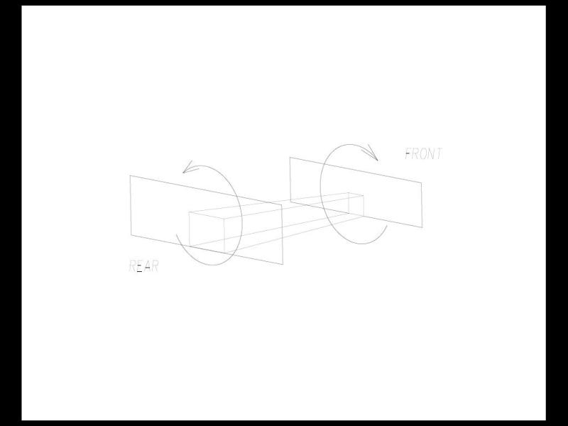
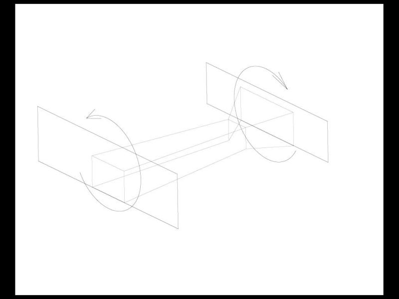
The most important thing is that the chassis does not twist along the longitutinal axis. Our roof does that for us. A 4 sided form is free to twist, but once you close the ends, making it a 6 sided box...it can not twist. Our central tunnel is not boxed, so can twist. By colesing it completly, it becomes a rigid torsion box. Doing that alone helps alot, but it still needs a wider front to tie into the front bulkhead. I did a drawing, but don't know how to attach a PDF file. (Help..??)
Thanks Yellow88 for emailing the pdfs. I converted them to JPG by viewing the PDF full screen, taking a screenshot (PrtScr) then opening MsPaint Paste (CTRL + V) then SAVEAS .JPG from Yellow 88's email: "Frame-1 is our tunnel". In the Fiero it is unboxed and free to twist. By closing the bottom completely, it becomes rigid, but It's front attachment is small so isn't as effective as "Frame-2".
I see what you mean by flairing out the front now. I do think that it requires a LOT of fabrication.... but not undoable. I see how it would increase the torsional stiffness.
quote
Originally posted by 86_IRM_TURBO:
There were references in the post that refer to a "static stiffness" number for vehicles. That nuber is basically measuring deflection with a known input force. Well........I happen to test vehicles bases on Frequency. The lighter and stiffer a structure is, the higher the bending and/or torsion frequency will be.
Most cars are designed as coupes or sedans and the first bending/torsion modes are in the mid to upper 20's. 23-29 Hz. generally.
When you cut the roof off they can drop into the low to mid teens. So the "X" and "Vee" braces are added to try to get the car stiff enough to have something for the suspension to react against. These braces can also add torsional stiffness to a non-chop top. Like the BMW Z4. They are less effecive in the bending or beaming direction.
If you can get a look at one of the cars I mentioned from underneath it would give you a good idea of how you might apply the same type of bracing to your car.
WOW! Thanks for you expert opinion, I could not have dreamt that anybody would respond to this thread who actually measures cars stiffness for a living. A real expert on this subject. I am currently searching the internet for pictures of the underside of the cars you mentioned. I'm very curious. I'll post pics if I can find any. Have you actually ever measured how many Hz a Fiero chassis has?? (care to make an educated guess)
Iwan
IP: Logged
07:06 PM
Jan 2nd, 2007
86_IRM_TURBO Member
Posts: 487 From: Commerce Township, MI, USA Registered: Dec 2006
I probably have some digital pics at work from some of the cars I've tested. I'll see if I can dig them up. I have not measured a Fiero because I started working in the Advanced Vehicle Development group back in 1995. I transferred from the Manufacturing Engineering side of the company back then. As for a guess on where the first bending & torsion modes...........I'm not really sure. Based on the shape of the structure I'd guess the torsion would be 2-4 Hz below bending. The greenhouse is short, and does not extend very far rearward. A shape like a Taurus would be better or even a fastback where the rear pillars and glass add to the structure.
I will ask some of the old timers at work if they know where the "P" car ended up.
I will be out working on my car again soon and when I do I'll lift it up and see if I can see good attachment points for adding some bracing.
IP: Logged
04:58 PM
fiero-iwan Member
Posts: 352 From: Eindhoven,Netherlands,Europe Registered: Mar 2003
I probably have some digital pics at work from some of the cars I've tested. I'll see if I can dig them up. I have not measured a Fiero because I started working in the Advanced Vehicle Development group back in 1995. I transferred from the Manufacturing Engineering side of the company back then. As for a guess on where the first bending & torsion modes...........I'm not really sure. Based on the shape of the structure I'd guess the torsion would be 2-4 Hz below bending. The greenhouse is short, and does not extend very far rearward. A shape like a Taurus would be better or even a fastback where the rear pillars and glass add to the structure.
I will ask some of the old timers at work if they know where the "P" car ended up.
I will be out working on my car again soon and when I do I'll lift it up and see if I can see good attachment points for adding some bracing.
Thanks for your response again! A few questions though, what is a greenhouse? So do you expect the fastback would actualy perform better than a notchy, does the plastic glass of the quarter windows add stiffness? I would not have thought of this...
Please keep us posted with any pics of the underbody of the cars you mentioned, I have had no luck searching the net for them (yet). and Yeah, maybe the older guys remember testing the fiero in its day (wonder if there is a stiffness difference in the 88 and earlier space-frames like a read somewhere..) Any ideas you have when you inspect the bottom of your own fiero (what year and model is it btw) are verry welcome inthis here thread.
quote
Originally posted by Mark A. Klein:
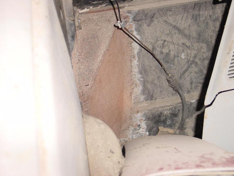
When I made my convertible, I installed a frame like the one pictured earlier. The frame drawing and pictures are from the convertible manual. I was not happy with the flexing of the body. To solve this problem I made a corner gusset behind the seats. This went from the B pillar (door) to the rear fire wall where the rear frame is spot welded in. Again this did not solve the problem until a put a cap on it. With it boxed in with a cap, I was amazed at how much stiffer the frame was. It is not very high, but the same height as a natural bend/seam in the B pillar. I think it was about 8 - 10 " in height. The only disadvantage was I lost the last 1" of so of travel in the most rearward position of the seat. I you do not set the seat all the way back, you would never notice. I also welded in the crush zone gap on the frame that sets upon the center tunnel on each end under the console. I always said I was going to do this to my 88 coupe just to stiffen the doors, ( I live on a gravel road) but have never gotten around to it. Good luck. I pressured enough I could take some pictures, If I can dig my way back to the car..... But I have never had luck with PIP. Mark
I would love to see some pics if possible Mark. Just email them to me and I'll post here. I have trouble picturing what you mean by boxing the gussetts behind the seats with a cap.... Sounds like it may be a really good idea! I would not notice the seats not going all the way back (my feet wouldn't be able to reach the peddels in rear position, LOL)
If at all possible could you explain or show where the crushzonegap is and how you strengthened that too?
There shouldn't be any appreciable difference between the notchback and fastback. The body panels on the Fiero are supposed to be unstressed, so the fastback's buttresses are non-structural.
Would it be possible for me to get a copy of that .pdf? You folks have piqued my interest.
EDIT: Forgot to add that greenhouse is another term for the cabin. More specifically, the part of the cabin from the roof down to the base of the windows.
[This message has been edited by Toaster_Man (edited 01-02-2007).]
IP: Logged
10:12 PM
Jan 3rd, 2007
86_IRM_TURBO Member
Posts: 487 From: Commerce Township, MI, USA Registered: Dec 2006
Hello again! Yes, sorry I didn't make that point very well. The Fiero fastback adds nothing to the structure. I'm off work ill today but I'm on the mend so maybe I'll have some pics of some underbacing for you guys tomorrow.
I would also like to see the pics of tying in the bulkhead as well. Always nice to see how others work on cars.
Oh, and thanks for the nice graphic of the tunnel. Very nice!
So far I have not figured out how to add pictures to the forum. Whats the trick?
Thanks!
IP: Logged
11:35 AM
86_IRM_TURBO Member
Posts: 487 From: Commerce Township, MI, USA Registered: Dec 2006
My car is.........well........an 86 SE Fastback. I'd pop up a pic for you but as I stated B4 I haven't figure out how yet. I tried pasting a pic in a word doc and putting it in. But that didn't seem to work either.
IRM built a few fastbacks to display at the SEMA show back in 85-86 I have one that actually has been extended in the rear trunk area. I can put my Coleman cooler in there. Sweet!
My car is.........well........an 86 SE Fastback. I'd pop up a pic for you but as I stated B4 I haven't figure out how yet. I tried pasting a pic in a word doc and putting it in. But that didn't seem to work either.
Bottom of this page, Pennock's Image Poster, little blue box with red corner.
IP: Logged
01:24 PM
86_IRM_TURBO Member
Posts: 487 From: Commerce Township, MI, USA Registered: Dec 2006
Just a few thoughts for strengthening. Tell me what you think.
Run a bar of whatever shape from top rear of B pillar to rear strut tower or frame rail. (don't remember how they tie together) Hide this in the notchback's rear sail panel edge.
Bolt-on panel -vs- an open cross-braced piece(a rectangle with x or triangulations in between the rectangle's edges).
What are possible ways to stiffen the front sub-frame to cabin connection. Would it be better to tie the front and rear sub-frames together thru the now boxed center tunnel, to the front and rear of the cabin, both or thru a separate torsion box tunnel placed inside the Fiero's tunnel bypassing the cabin.
(Funny... the spell checker on this forum does not recognize the word Fiero as a correctly spelled word.)
Just by looking at it (and I've spent quite a bit of time doing that) I would say that a t-top conversion is about the same as a regular Fiero as far as longitudinal (front to back) rigidity. Unfortunately, the t-top car really looses out when it comes to torsional rigidity. Remember that all Fieros are built with a sunroof cut out, so there are essentially 2 supports at the outboard edges tieing the tops of the A and B pillars together. These supports resist changes in the position of the A-pillar in relation to the B-pillar, and in effect make it harder for the chassis to twist about its longitudinal axis. The t-top car has these 2 outboard supports cut out and replaced with a single inboard support that is simply too flexible to offer that same torsional rigidity.
The t-top H-frame itself is a lot floppier than you would expect. It gets its strength from the fact that it is resistant to compression and tension as long as it doesn't bend. Since the frame is held into the car with 50 rivets (that's an awful lot of rivets if you think about it) there isn't really a lot of room for the chassis to move without putting the H-frame in either compression or tension.
If you can wait, I will get pictures of the box sections. Problem is, it is dark when I get home, and no lights where the car is stored. Saturday is going to be spent with my son interviewing the college he wants to attend. Sunday is church and preparing a rental tobe moved into.... But keep reminding me and I will get pictures to post....
IP: Logged
10:19 PM
PFF
System Bot
Jan 5th, 2007
86_IRM_TURBO Member
Posts: 487 From: Commerce Township, MI, USA Registered: Dec 2006
I now have some pics of some sample Vee braces. PIP locks up my PC so I still can't upload pics. I'll be happy to e-mail them to anyone who asks.
I spoke to our Structural expert this afternoon and he's going to try yo find out if there are any data in the archives about the structure modes of the Fiero.
I'm going to guess that based on the feel of my car that the torsion is around 17Hz and bending at around 22-23Hz. If I get a chance this spring/summer I'll try to get a quick measurement of my car in the work parking lot.
Roof structure is KING in the torsional direction. The (old) Chrysler Sebring dropped from 23 to 13.5Hz torsion cutting the roof from the coupe. We tested a mid-sized sedan once to find the difference between a standard sunroof opening and one of the very large glass segmented panel items. The missing shear panel dropped the torsion 3Hz and bending a mere .2Hz.
I'll dig some more out later but these give the general idea I think. The Vee braces are for the front and/or rear of the car to help control the "Wagging" or body in torsion motion, they would connect from an attatchment point as far rearward/foreward as you can get to the structure and back to a centerline point.
The X braces are used to criss-cross the main body structure attatching typically to the lower rocker area at the pinch weld flange. This is a good spot (for most cars but not Fieros) to get a good hold of the body structure. As you can see from the pics rectangular tubing works well for this and is not extremely heavy. The braces range from 25-45Lbs per package and are very efficient.
[This message has been edited by Toaster_Man (edited 01-06-2007).]
IP: Logged
07:01 PM
Jan 9th, 2007
Mark A. Klein Member
Posts: 608 From: Pleasantville IA Registered: Aug 2002
Just to add to your thinking. Solid aluminium will stiffen the frame. We use 1/4" in the front and rear of our rally cars. This is of course to primarily protect the engine and drive train but it has the added effect of stiffening the frame because we need as much stiffening as we can get. But as mentioned it does create lift when you are pushing above 200 kph. With the EVO or Talon we curve it to create lift because they are more front heavy than the Subes so need help keeping the front up on jumps. I find that my fiero is too light in the front end so I would discourage doing anything that would increase lift.
IP: Logged
11:54 PM
Jan 10th, 2007
datacop Member
Posts: 1426 From: Indianapolis, IN, USA Registered: Jan 2004
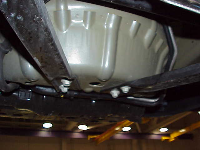
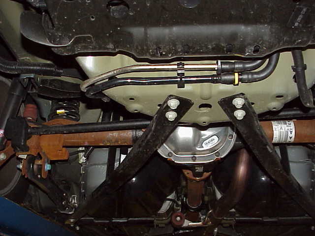
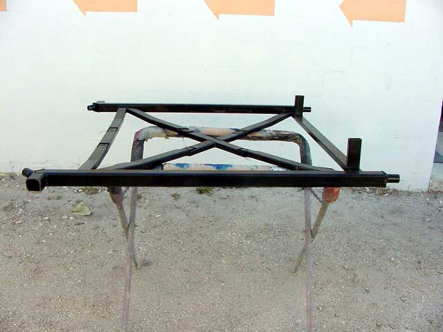
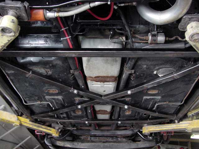
The X-Brace is the only thing that B&B did right.. but then again, B&B didn't make it, they just installed it.
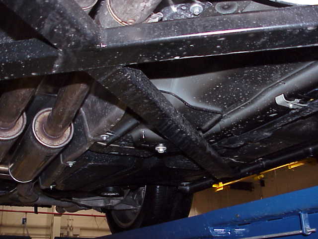
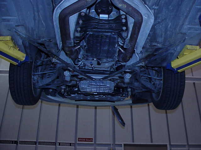
An interesting thing is.. Chester had them close off the ends of the underbody X-Brace and put nipples on the end for A/N fittings for the coolant system so that he could make double use of the frame to replace the coolant pipes...
Notice that the center part of the x-brace is bolt in so that the gas tank can be removed without having to remove the entire sub-frame.
IP: Logged
11:35 AM
Yellow-88 Member
Posts: 819 From: Coventry CT. Registered: Feb 2005
The X-Brace is the only thing that B&B did right.. but then again, B&B didn't make it, they just installed it.
An interesting thing is.. Chester had them close off the ends of the underbody X-Brace and put nipples on the end for A/N fittings for the coolant system so that he could make double use of the frame to replace the coolant pipes...
Notice that the center part of the x-brace is bolt in so that the gas tank can be removed without having to remove the entire sub-frame.
Those pics of this X-brace got my interest bigtime. Than... the cold engineer in me immediately went to the computer and did a model of it. Entering a rather large longitudinal twist of 5 deg., Mr. Computer indicated a defection of a mere .02�. Being that the thing most likely mild steel, and is bolted not just to the frame, but it bolted together, I would guess that it�s a useless ad-on.
Please�.don�t see me as throwing cold water on this�.but did any one actually measure this brace..??
IP: Logged
12:41 PM
PFF
System Bot
86_IRM_TURBO Member
Posts: 487 From: Commerce Township, MI, USA Registered: Dec 2006
The brace itself looks like a good structural member. It is not clear though that it is attatched to any stucture of the vehicle. If so, yes it should help. (especially a chop-top)
One thing I have learned by working on this kind of modification of a vehicle though is that "single point" attatchments to structural members is NOT a good idea. Even the bolts that allow the center section to be removed for the tank service would be well served to be double bolted. If there is enough over-lap this could be done to the brace shown very easily.
IP: Logged
01:06 PM
datacop Member
Posts: 1426 From: Indianapolis, IN, USA Registered: Jan 2004
The "X" brace shown is VERY similar to the one that Ford uses on the T-bird convertible except that the Tbird does not carry the tubing around the exterior of the rectangle. So even though the Thunderbird is not all that great torsionally, you'll find out how SCARY one is to drive if you drive it without one! (I know)
If it were mine though, I really would modify those joints.
Sorry I didn't get these up last night guys. It was the monthly Gateway Fiero Club meet so I didn't get a chance to get on the forum.
quote
email from Mark A. Klein:
To me that doesn't seem like the logical place to put a support. If the car was going to sag anywhere I kind of figured it was going to do it between the front and rear door frames. I know that when someone was doing T-Top installs (Ed Parks I think, but I can't swear to that) they were supporting the car by putting a jack under either side of the car at the jacking point in the frame rail. Then they jacked it up enough to stop the car from sagging (thus taking the pressure off the doors) and to spread the opening up to put the H-frame in. They did this in lieu of using the spreaders that C&C used to adjust the gap before riveting. Now that I think about it, they might have even needed help flexing the car to widen the opening. The weight of the car itself wasn't enough so they had a guy sit on the hood and another on the trunk.
IP: Logged
04:33 PM
Mark A. Klein Member
Posts: 608 From: Pleasantville IA Registered: Aug 2002
The gussets were not installed to support the car. It has a welded in X frame like shown in the previous page. When driving down the road the body flexed terribly. After the gussets were installed the flex was greatly reduced. I live on a gravel road..... The frame welded in goes from the front cross member to the rear B pillars. It is a rectangle from both A pillars to both B pillars. Then the extensions go to the front cross member, lastly the retangle was boxed. The frame still flexed considerably. The doors rattled on the gravel road. The gussets solved this.
edit spelling
[This message has been edited by Mark A. Klein (edited 01-10-2007).]
# Make a connection to the internet # Start PIP by choosing it from the Start Menu # Click the New button # In the Automatic Configuration Field, type: https://www.fiero.nl/fieroforum.pip # Click the Get button # Make a connection to the internet # Start PIP by choosing it from the Start Menu # Click the Browse button # Choose the image you want to include # Click the Post It! button # In your message, press Ctrl-V
IP: Logged
05:01 AM
Robert 2 Member
Posts: 2401 From: St Hubert Quebec Canada Registered: Jan 2006
# Unzip it and run SETUP.EXE # Make a connection to the internet # Start PIP by choosing it from the Start Menu # Click the New button # In the Automatic Configuration Field, type: https://www.fiero.nl/fieroforum.pip # Click the Get button # Make a connection to the internet # Start PIP by choosing it from the Start Menu # Click the Browse button # Choose the image you want to include # Click the Post It! button # In your message, press Ctrl-V
IP: Logged
05:06 AM
86_IRM_TURBO Member
Posts: 487 From: Commerce Township, MI, USA Registered: Dec 2006
I tried and TRIED.......and tried........to get the PIP to install. For some reason when it's loading the "config" info it just never finishes the setup. It eventually times out the connection, but to get the PIP setup windows to go away requires me re-booting the PC. Anyone have an idea what could cause this?


 Sweet!