I'm not going to be able to do this all at one sitting, but I've been studying this and thought I'd get started with what I've been able to figure out on the system as time permits.
I've been looking at a service manual and wiring diagrams for the MR2 ElectroHydraulic Power Steering system. First things first, the rack appears to be a conventional power steering rack. I don't see any particular difficulty beyond having custom lines made to use the MR2 system on the F body or Corvette racks. The system also appears to be simpler than I first thought it was.
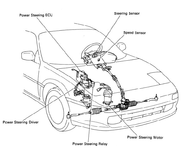
First, a layout of the components.
Six basic components not counting the rack itself.
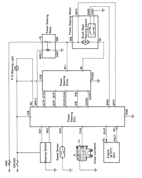
Next I'm going to go ahead and post the wiring diagram of the system itself, so we have that out of the way.
Taking the components one at a time, I decided to look at the things that GM doesn't use at all, and the first thing on the list is the steering position sensor. On the MR2 this is behind the wheel and it's fairly simple, the way I look at it. It basically sends a signal to the PS computer that tells it if the steering wheel is more than 36� off of center. I need to do some more reading on just exactly how this works or, better yet, it would take about 15 seconds with an ohmmeter if I had an actual MR2 to play with, but what happens (it appears) is when the wheel is centered, both leads go to ground through an approximately 100 ohm resistor. When you turn the wheel one way, one of the lines goes to infinity, and when you turn the wheel the other way, the other line goes to infinity. So basically it's an On/Off switch if the wheel is left or right 36� off center.
There are two really critical components in the sytem. The first is the PS ECU, the second is the motor controller.
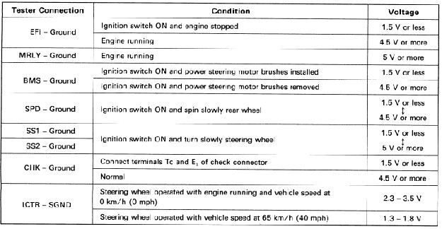
The motor controller gets voltages from the PS computer anywhere from 3.5V at 0 vehicle speed to 1.3 V at speeds above abot 40 mph. It appears that the curve is linear, but they don't really say so that's conjecture on my part. The controller then takes the battery voltage and based on the voltage it sees from the PS Computer, converts that to anywhere from 11V to 2V. The motor can draw up to 65 amps and has an 80 amp fusible link.
I'm still reading about this and I'm beginning to wonder if things might be more complicated than we need them to be. The MR2 already has the motor controller, so what we basically need is a circuit that would vary the input voltage from 3.5V to 1.3V based on how fast the car is going. If that's the case, I don't see a major hurdle in designing a circuit (for those that understand this stuff far better than I) to simply read the Fiero VSS and have a graduated curve that would vary output voltage from 1.3V to 3.5V to send to the controller, which could then do it's thing in powering the electro hydraulic pump.
Here are the inputs and outputs from the PS computer
All in all, I'm encouraged, but I haven't really been able to look closely at the manual. For instance, I don't know what the PPM of the VSS is. Will that have to be converted or can the Fiero one be used as is? (If we try to stay with the stock computer from the MR2 and Motor controller)
I do believe the guy with the jeep that put the MR2 steering in it has a working system, but the amp draw running full speed all the time has got to be high and it's going to have to shorten the life of the motor somewhat.
If there's anything specific you want me to look for, let me know, otherwise I'll just keep poking around and see what else I can come up with that might be of help.
John Stricker
IP: Logged
03:19 PM
PFF
System Bot
May 20th, 2006
RCR Member
Posts: 4430 From: Shelby Twp Mi Registered: Sep 2002
John, Like I mentioned in the other thread, this is a project that does interest me. I've followed all the powersteering threads closely. It's also quite a coincidence, but I sat in a meeting yesterday at work in which I was handed a project that will involve converting steering wheel position to a specific signal that goes to a power steering control module. It may be a little more advanced than what you need, but I think I can apply some of that technology to your project. Converting the Fiero Vss signal to meet the requirements of the PS controller should be fairly easy, just need the parameters. Let me know if and when I can help. I can donate my lunch time at work for you.
Bob
IP: Logged
06:29 AM
Derek2M6 Member
Posts: 289 From: Guelph, Ontario, Canada Registered: May 2006
Great stuff; I am hoping to progress on a similar set up once I get my engine rebuild done. Electronics aren't my strong suit, but I have pulled together some of the wiring diagrams for the MR2 (as I see you have). I got a MR2 PS setup with all the PS electronics a while back on ebay. The speed signal and steering position sensor don't appear to be impossible. Looking forward to our progress and will let you know as I move forward with my work
IP: Logged
01:07 PM
Ken_86gt Member
Posts: 574 From: WILLIAMSBURG Registered: Jan 2004
You could probably use a LM2907 chip, which can operate a tachometer type of output and then put a op-amp after the circuit to invert the voltage. The LM2907 will give an output of 0 when the frequency input is 0, and 12 v when at max freq. The op-amp could invert the output to be 12v at 0 hz and 0 V ant max freq. You would have to do some calculations to get the output you are looking for. And then shift the voltage to the range that you were looking for 3.5 v to 0 v.
I think what I'm going to do is put some of the relevant information up on some server space so it will be there for you guys to reference, but it might be a day or two before I can get that done.
I'd like more opinions on some things I'm thinking about and I think you'll all need more information before you can offer informed opinions. My thinking right now is that I'd like to do away with the PS Computer if at all possible and simplify things a bit. Here is my thinking on it.
The motor controller would be used. It would need a speed sensor circuit that would vary the voltage from between 1.0V or thereabouts and 3.5V or thereabouts that is inversely proportional to speed from 0 to 40 mph or so. The more voltage fed to the controller, the more it feeds to the pump making it put out more. Thinking through this, the reason it has a steering wheel position sensor is because when you're parked in traffic, for example, your vehicle speed will be 0 so the pump would be getting max voltage, but since you're not turning the wheel the pump doesn't need to work that hard. I do see why they'd want it to run SOME, because if it didn't and started from "off" to max power suddenly it would give a very noticeable "kick" to the steering wheel.
At first as I read the manual, I thought it indicated it just went back and forth from ground to open to indicate when the wheel wasn't at dead center. Now I'm not so sure. If you look at the last chart I've posted, it shows lines SS1 and SS2. Those are the lines coming from the steering wheel position sensor. As I read this, it looks the same as the pulses coming from the VSS which is indicated by the line SPD. They get that signal an odd way, and I'll have to post what limited pictures they have of the sensor, but I'm thinking now if the computer sees pulses from these lines, it "opens the door", so to speak, and allows the controller to do it's thing based on speed. If there are no pulses, it lets it drop down to that minimum level.
If that's the case, a circuit would also have to be created that would throttle the system in that way if we're going to eliminate the computer.
Thoughts? Ideas? Comments??
John Stricker
IP: Logged
07:54 PM
Aug 25th, 2006
Formula88 Member
Posts: 53788 From: Raleigh NC Registered: Jan 2001
Awesome information jstricker, thanks for sharing. I have ordered the factory manuals and will be looking into this as well. Does anyone know the duty cycle of the MR2 pump? I assume it is not 100% and that is the reason for the steering position sensor. This steering position sensor really is the last bit of the puzzle. Making our own computer would not be difficult as long as we only have to handle low amperage signals.
I'd like to know how that sensor works, if they are attainable at parts stores (dealers), and how much one costs. If its not too much, we could find out its output and I don't think it would be too hard to incorporate it into our home-made DC speed controller. What you said as far as how it works with the computer makes sense to me.
Edit: found the manuals online and it talks about the computer needing a speedometer signal of 40 cm per pulse which is roughly 4000 pulses per mile - the same as the fiero signal before the divider circuit. jscott has said that 1988 fieros have an extra 4000 ppm output that isn't used (probably intended for GM's version of the same controller)...convenient, eh?
[This message has been edited by TG oreiF 8891 (edited 10-19-2006).]
IP: Logged
01:38 PM
Nov 10th, 2006
TG oreiF 8891 Member
Posts: 776 From: Cleveland, Ohio; USA Registered: Aug 2004
I got a hold of an MR2 manual, but so far, it looks like the parts are going to be quite expensive. If anybody knows where I can get the two computers, steering sensor, and electric pump for say <$300; please let me know. I'd be hard pressed to pay much more for something I'm not sure I can easily make work.
IP: Logged
04:54 PM
jstricker Member
Posts: 12956 From: Russell, KS USA Registered: Apr 2002
During the summer I have no time to really work on/experiment with this kind of stuff. I'm hoping to get back to it this winter, but probably not until after Jan 1.
John Stricker
IP: Logged
06:45 PM
jscott1 Member
Posts: 21676 From: Houston, TX , USA Registered: Dec 2001
During the summer I have no time to really work on/experiment with this kind of stuff. I'm hoping to get back to it this winter, but probably not until after Jan 1.
John Stricker
I'll give you a dollar if you start on it right now. If 10,000 others join in with me, it might be worth your while.
IP: Logged
08:01 PM
PFF
System Bot
jstricker Member
Posts: 12956 From: Russell, KS USA Registered: Apr 2002
I don't know if, or when you are planning on getting back into this, but if you do, please send me an email / PM. Hopefully we can help each other out. I have the wiring diagrams and I just purchased the wiring harness, computer, driver, and relay from an MR2. We'll see what kind of shape it is in when it gets here.
IP: Logged
01:15 PM
May 20th, 2007
rkisling Member
Posts: 69 From: San Francisco, CA USA Registered: Aug 2003
I am very interested in your progress. I picked up a complete, with all electronics, MR2 power steering pump and have a F-Body rack. Am still putting the engine back in (will get it back on the road this year). But am very intersted in this mod. Ihave looked at the wiring diagrams, and understand what is needed, but the specific electronics are beyond my capabilities.
IP: Logged
12:19 AM
TG oreiF 8891 Member
Posts: 776 From: Cleveland, Ohio; USA Registered: Aug 2004
I am very interested in your progress. I picked up a complete, with all electronics, MR2 power steering pump and have a F-Body rack. Am still putting the engine back in (will get it back on the road this year). But am very intersted in this mod. Ihave looked at the wiring diagrams, and understand what is needed, but the specific electronics are beyond my capabilities.
The electronics are really beyond my abilities too, so unlike John, I am planning on duct taping the entire MR2 system into the Fiero. For me, it is simpler, because I don't have to figure everything out, only a few inputs: power, ground, speed. I have learned that the Fiero's 4000 PPM VSS signal is almost exactly what Toyota was using, and the signal from GM speedometers of the same vintage including the Fieros and the S-10's seem to work just fine directly without any conversion.
I have all the electronics except for the steering position sensor, and the pump is on its way to me now. I am toying with the idea of replacing the steering position sensor with an RPM and timer. What I want to do is idle the pump when the RPM's stay below 1000 for over 5 seconds. I think this would limit the pump's operation enough to lengthen its life without resulting in any operational problems, and I really don't know how to rig up a steering position sensor, plus Toyota wants close to $200 for one. That's too much for a component I'm not sure I can make work correctly. Besides, I don't think running the pump full out while stopped at a light will be too awfully bad on it. When you aren't turning the steering rack, the fluid is simply running in a loop with few restrictions. It's a free-flowing loop and should take low amperage to operate. The high voltage signal from the computer will make the flow rate very high, but it shouldn't be very hard for the pump to move the fluid that fast because nothing is restricting flow. As you turn the steering wheel, you open valves in the power steering rack, and the pump will have to draw a significant amount of amps to continue operation. This is where long periods on continuous use would have the potential to shorten the life of the pump.
Anyway, if you'd like to compare notes or just chat about the system and how to get it in there, PM me and we can contact each other.
Well, it looks like this thread died a slow and terrible death. I thought I'd add one last post to say, "IT'S IN"!!!!! I got the corvette power steering rack (2.0 turns lock to lock) installed and the entire MR2 electronic setup (PS computer, PS driver, and PS relay) installed and working in my 88 GT. It went to the alignment shop today, so I won't know how it drives until I've had a chance to try it out. Eventually I'll get around to making a build thread out of all the pictures I have hopefully before I forget everything I learned.