i am currently in the process of wiring up my 3rd 3.4 dohc engine. the first was my car. i bought it already swapped with a 92' engine. it was a complete mess. i ended up going to the junkyard and getting all new wiring and starting over just to get it somewhat cleaned up. the second was a 95' harness. i did it for free and sad to say i did the bare minimum to get the car running and left all the routing of the wires and clean-up to the owner. this time is different. one, i'm getting paid. two, i have a completely uncut 1995 harness. i don't really care for doing this so i figured i would share it here so others can do it themselves, and i want to try and cover a few things that i've seen wrong in the past. for connections i am using butt-connectors that come with a shrink covering and splooge inside them for a weather tight seal. these connectors require a good ratcheting crimper. do not use the cheap walmart brand. also do not use the cheap butt connectors. if you don't want to spend the money on butt connectors and a crimper, use rosin core solder and shrink tube. don't overheat the tube and split it and get lazy and pretend you didn't see it either. i'll start a new post for each circuit so it's easier to search later. it will probably take a week or so to get this done. i keep forgetting my crimper at work.
IP: Logged
01:57 PM
PFF
System Bot
joshua riedl Member
Posts: 1426 From: watertown wi USA Registered: Jan 2004
CUT OFF THE RS ELECTRICAL CENTER AND THE BULKHEAD CONNECTOR FROM THE DONOR CAR. completely get rid of them. then carefully unloom and untape the harness using zip-ties to keep everything organized. this will leave several wires loose between the two connectors. pull them out through the zipties and discard them. you can also remove the solenoid wire and a couple charge wires to clean up the harness some more. these will be installed last when you put the engine back in the car so yu don't need the mess now. remember to keep the harness organized with the zipties. at this point everything should still be clean and organized.
IP: Logged
02:03 PM
AaronZ34 Member
Posts: 2322 From: Colorado Springs, CO Registered: Oct 2004
I'm keeping a sharp eye on this one as I will be using 94-95.
------------------ "all pushrod motor are better than the dohc because it has less rotational mass" -rick17, MyMonte member, owner of a 3100 Monte Carlo LS
CUT OFF THE RS ELECTRICAL CENTER AND THE BULKHEAD CONNECTOR FROM THE DONOR CAR. completely get rid of them. then carefully unloom and untape the harness using zip-ties to keep everything organized. this will leave several wires loose between the two connectors. pull them out through the zipties and discard them. you can also remove the solenoid wire and a couple charge wires to clean up the harness some more. these will be installed last when you put the engine back in the car so yu don't need the mess now. remember to keep the harness organized with the zipties. at this point everything should still be clean and organized.
I preffer to usebrown masking tape so that I can write what that group of wires is for makes splicing into the fiero harness easier later
IP: Logged
03:32 PM
joshua riedl Member
Posts: 1426 From: watertown wi USA Registered: Jan 2004
OPEN UP THE BULKHEAD CONNECTOR FOR THE C203 CONNECTOR. this is assuming that you have already removed the harness from the fiero. i used a heat gun. it is pretty easy and i only had to heat it for a couple seconds to pull it apart. you can try and save the wiring for the relays that go through the bulkhead or if it is too tangled up just cut the wires off the relays leaving as much length as you can. i will cover later on how to hook up the A/C and fuel pump relays. there are a couple wires that go directly from the c203 to the fiero ecm. cut them as close to the ecm as possible. now you can pull out all the wires for the fiero ecm and put them in your spare parts pile. at this point you should have a c203 connector with wires a minumum of 10 inches long. some probably a couple feet. you should also have two relays that may or may not be connected to the c203. mine at this point are cut. so i have seperate pieces i will be putting back together. the reason i used zipties on the dohc harness is so i can pull out the unused wires and still keep everything in order. if you think you will be confused on which bundle was which go ahead and label them. but we will be able to trace the wires from their source so i don't find it a necessity.
IP: Logged
07:35 PM
joshua riedl Member
Posts: 1426 From: watertown wi USA Registered: Jan 2004
CUT THE WIRES FOR THE C500 AND LABEL THEM. the c500 is the one on the passenger side by the battery. you can get the pinouts from dohcfiero.com i will also be covering each step with pinouts later but this will help speed up the process and avoid confusion because some wires are identical or really close in colors. again, be sure to leave enough slack to splice to. i just find it easier to cut them and then route them seperately as needed. the plugs do have numbers and letters to find the location. going by the colors alone is not good enough.
IP: Logged
07:43 PM
Dec 23rd, 2005
bonaduce Member
Posts: 1594 From: witness protection Registered: Oct 2002
great info here, as i also am using a 95 harness. Just for referenece to us "extremely" non electical guys, if pics are available to the conections you are cutiing it might be helpful to those who plan on doing their own harness. I myself will be paying someone (lol). just a suggestion.
i think people should wait until i'm finished because there are going to be a few wires i can't do so they will just be labeled for installation later. so when i'm finished with this one and it is satisfactory for you then we can talk prices.
FUEL PUMP RELAY PIN B the fuel pump is by far the most difficult part of the wiring. it requires interaction between the fiero fuse box, the new ecm and the oil pressure sensor. i dred it so much i wanted to get it over with first, and if you can follow me through this the rest of the wiring will be easy. i am going to cover one pin per post to try and make it easier to follow. first connect, or be sure it is still connected, pin B of the fuel pump relay to pin L of the c203. it will pass through the imaginary bulkhead connector that we removed earlier. now find the oil pessure sensor. locate the grey wire on pin C and follow it. you will find that it splits in the factory harness. cut off one side of the split and use it to lengthen the remaining side. i chose to use the removed C100 as a new path that will go behind the engine and meet up with the driver side bulkhead connector that we removed earlier. extend the grey wire, pin C, to splice into the first wire we did in this post. what GM did was route the fuel pump relay power into one bulkhead connector, through the C203 and then loops back out the other bulkhead connector to the fuel pump connector. now you can use an ohm meter to check the oil pressure sender pin C, to the relay pin B,and to the c203 pin L. this is not the same wiring as the 91-93 engines.
[This message has been edited by joshua riedl (edited 12-23-2005).]
IP: Logged
10:55 PM
joshua riedl Member
Posts: 1426 From: watertown wi USA Registered: Jan 2004
FUEL PUMP RELAY PIN A it is a dark green/white wire and needs to be lengthened to to pin D1 on the ecm. D is the brown connector. the colors matched up on this one with dark green/white. i used my new path to the driver side bulkhead connector to route this wire. this is the ecm control, without it your fuel pump won't run until your oil pressure switch closes. this is also what primes your fuel pump for a couple seconds before you start the car. listen for this the first time you start it as a check. now you can go back and ohm out your new circuit.
[This message has been edited by joshua riedl (edited 12-23-2005).]
IP: Logged
11:08 PM
joshua riedl Member
Posts: 1426 From: watertown wi USA Registered: Jan 2004
FUEL PUMP RELAY PIN C this is simply a ground. the fact is the harness i'm working with was previously cut so i think this wire may have went to the c203 and got a ground through the dash area. check for this. if the wire is loose just put an eyelet on it and ground it right to the fuel pump relay mounting bolt, short and sweet.
[This message has been edited by joshua riedl (edited 12-24-2005).]
IP: Logged
11:11 PM
joshua riedl Member
Posts: 1426 From: watertown wi USA Registered: Jan 2004
FUEL PUMP RELAY PIN D find the oil pressure sender again. find pin D the orange wire and follow it. you will find that it splits off to several places. two of them are ecm powers, pins B22 and B11. extend one orange wire along our new path to pin D on the fuel pump relay. pin D on the relay has two wires comming out of it. the other wire may still be connected to pin B on the C203, if not, connect it. on my harness this left two orange wires not used. i will cut them at the splice and tape it. the stock dohc uses a 20 amp fuse for this circuit. the fiero uses a 10. you will need to upgrade this fuse. now go back and ohm the FPR pin D to the OPS pin D and c203 pin B.
IP: Logged
11:30 PM
joshua riedl Member
Posts: 1426 From: watertown wi USA Registered: Jan 2004
OIL PRESSURE SENDER PIN A it's not really a part of the fuel pump relay but it is the last wire for the OPS plug. find this wire, it's tan, re-route and extend it along our new path to pin E on the C203. this will give you your oil pressure reading, although some are switches instead of resistors so your needle might be pegged. congratulations, you just finished the hardest part of the wiring. now go back and check your work.
IP: Logged
11:38 PM
SLOWnSTEADY Member
Posts: 1706 From: Hiawatha, IA Registered: Jul 2005
well, im gonna have to run a 94-94 harness, so ill prolly try this out. where can i get a wiring diagram or somethin, so i know what the hell you talkin about with all those numbers and such?
IP: Logged
11:55 PM
Dec 24th, 2005
fieromadman Member
Posts: 2217 From: Oconomowoc WI, USA Registered: Jan 2003
http://www.dohcfiero.com/Factory%20ECU.htm is where you can find some information, and pictures that tell you what connector is what. Just so you know, the harness that they are using is the earlier 91-93 harness that has different ECM pins and whatnot. I should be able to post some tables of what each pin on the 94-95 harness is.
I will be at josh's tomorrow to take a ton of pictures! BTW, the harness that he was talking about in his first post with doing for free and letting me route all the wires and him just making the connections.. well that one was mine! Thanks alot Josh!!
Originally posted by fieromadman: BTW, the harness that he was talking about in his first post with doing for free and letting me route all the wires and him just making the connections.. well that one was mine! Thanks alot Josh!!
He did something right because your car is sure running beautifully this weekend.
IP: Logged
12:53 PM
PFF
System Bot
fieromadman Member
Posts: 2217 From: Oconomowoc WI, USA Registered: Jan 2003
Josh got a little further along on the wiring today, and he'll be on in a second to describe what he did. I'm just the picture poster, so dont ask me questions.
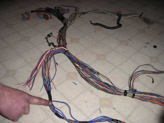
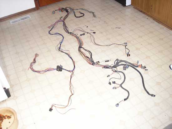
So heres some general pictures of the harness:
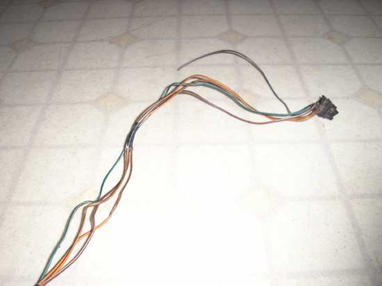
Here's the new routing to the drivers side bulkhead pass-through.
another shot of the same thing:
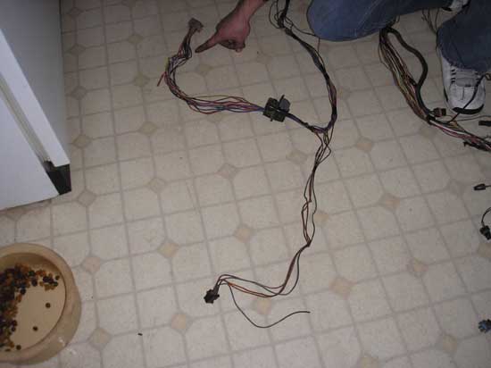
On the bottom here is the fuel pump relay and the top is the C203, after going through the bulkhead connector.
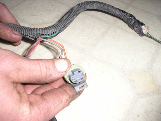
A close up of the fuel pump relay. The loose wire will be getting grounded to the frame.
Oil pressure switch/sending unit connector
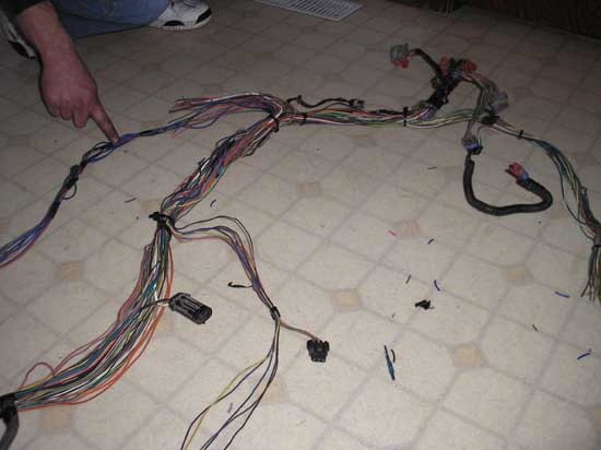
An overview of the whole harness:
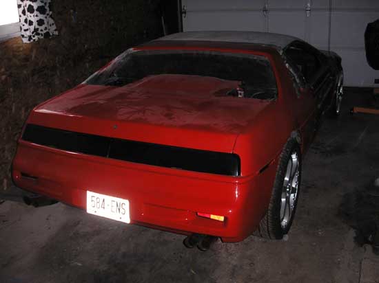
And Josh's choptop, for those of you that havent seen it.
Thats it for now for pictures, if you people want to see some specifics I can always go back and shoot some more pictures, but you have to tell us what you want to see.
IP: Logged
02:28 PM
joshua riedl Member
Posts: 1426 From: watertown wi USA Registered: Jan 2004
CHECK ENGINE LIGHT find pin C on the C203 connector. it is a brown/white wire. connect it to A1 on the ecm. A is the grey plug. it is also a brown/white wire. connect these two together using the new path we made to the driverside bulkhead passthrough. now go back and ohm out the wire.
IP: Logged
02:36 PM
joshua riedl Member
Posts: 1426 From: watertown wi USA Registered: Jan 2004
SWITCHED POWER FOR THE ECM use pin F on the C203. it is a pink and black wire. find B5 on the ecm, B is the red plug, it is also a pink wire. follow this wire and you will find that it also splits off to the MAF sensor. at the split route the extra wire to pin F on the C203 using the new path. upgrade the fiero ignition fuse to a 15 amp. now go back and ohm the wires between C203 pin F, MAF and pin B5 on the ecm.
IP: Logged
02:42 PM
joshua riedl Member
Posts: 1426 From: watertown wi USA Registered: Jan 2004
VSS HIGH the vss has two wires one purple the other yellow. find pin G on the C203, it is yellow. now find the dohc vss plug. you will find that the yellow wire runs right to the ecm. run the yellow wire from the C203 down the new path and tap into the vss yellow wire. it should be noted that the earlier year dohc seem to need the yellow and purple wires switched. i'm looking at the wiring diagram right from a 95 monte service manual, the good one from the dealership, and it seems that everything matches up. if your speedometer doesn't work you can try switching the wires to the ecm. for now i am leaving the dohc vss plug on the harness. there is nothing i can do about this now, so it will have to be changed when it's time to go in the car. now ohm out the wires from pin G on the C203 to the yellow wire on the vss, which is pin B.
IP: Logged
02:49 PM
joshua riedl Member
Posts: 1426 From: watertown wi USA Registered: Jan 2004
FUEL INJECTORS find pin J on the C203, it's a pink and white wire. the dohc has two big connectors on the top of the engine that route to the engine's mini harness. do not touch anything on the engine side of this plug. find the grey engine connector(C104) and locate pin A, it is a pink wire. reroute this wire to pin J on the C203 using the new path. upgrade the fiero fuse TBI INJ 1 to a 15 amp. now ohm out wires C203 J to C104 A.
IP: Logged
02:58 PM
joshua riedl Member
Posts: 1426 From: watertown wi USA Registered: Jan 2004
ALTENATOR FIELD COIL this one is nice, it covers about 5 different things at once. find pin K on the C203, it's pink. there is a splice pack of brown wires about 18 inches from the ecm. the most accurate way to locate it is find pin B on the grey C104 engine connector and follow it. you will find that it splits to the altenator, the egr, the powersteering switch(probably cut off if you followed my instructions), and the evap purge solenoid. route pin K on the C203 to tap into one of the brown wires in the splice pack. now ohm out all wires and cut off the remaining ones at the splice pack and tape them.
IP: Logged
03:05 PM
fieromadman Member
Posts: 2217 From: Oconomowoc WI, USA Registered: Jan 2003
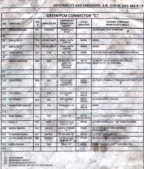
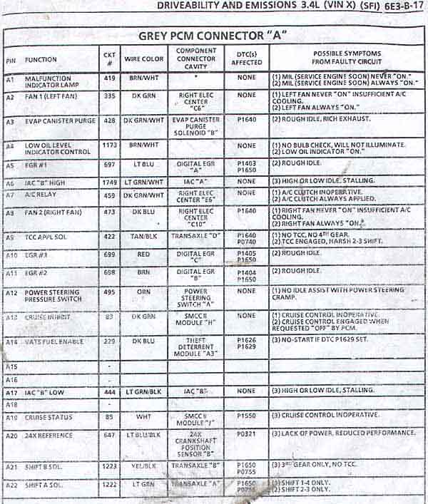
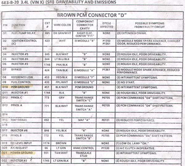
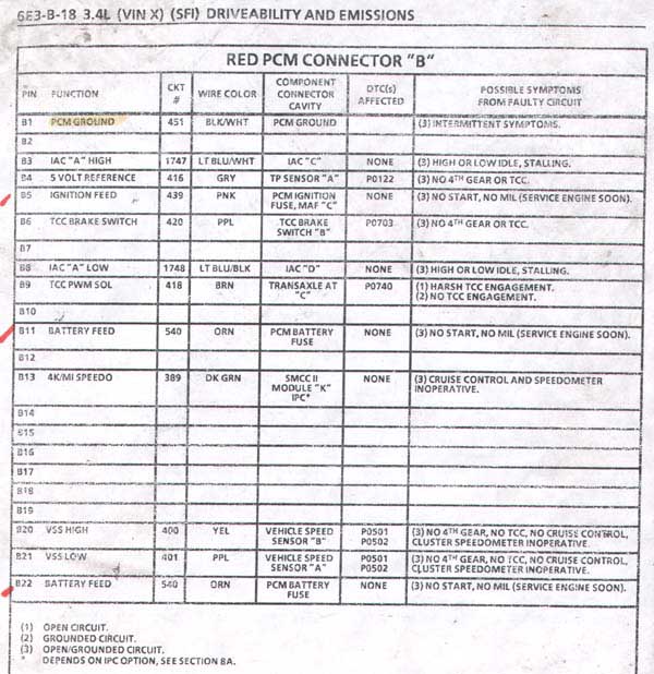
Whilei was at it, i scanned all of the ECM connector charts for the 94-95 since they are so different from the earlier ones and i dont believe that there is any charts ont he internet for these yet.
So here they are, sorry for the larger size but i had to get them to be readable. if anyone needs larger versions they will have to be e-mailed, but you should be able to read these.
at this point we are done with the C203 as far as getting the car to start goes. we should have a working fuel pump and oil pressure gauge. the injectors should be firing, the MAF is sensing, the ecm has both switched and constant voltage. the altenator will charge along with the heated O2 sensor and EGR and EVAP purge canister. the speedometer is reading. off the top of my head i would say that if we gave the coils power and the ecm grounds, this car would start. i'm done for the weekend but next week i'll tackle the C500 and a few loose ends and store my nice new harness in a safe place until i get my windshield.
[This message has been edited by joshua riedl (edited 12-25-2005).]
IP: Logged
03:12 PM
joshua riedl Member
Posts: 1426 From: watertown wi USA Registered: Jan 2004
well, im gonna have to run a 94-94 harness, so ill prolly try this out. where can i get a wiring diagram or somethin, so i know what the hell you talkin about with all those numbers and such?
when i'm done with this you shouldn't need a wiring diagram. all the letters and numbers i'm talking about are right on the plugs. if you really want a diagram you can buy the cheaper repair manual at autozone or get the good manual from a dealership or ebay. i was lucky enough to aquire some photo copies.
[This message has been edited by joshua riedl (edited 12-24-2005).]
IP: Logged
08:20 PM
PFF
System Bot
Dec 26th, 2005
joshua riedl Member
Posts: 1426 From: watertown wi USA Registered: Jan 2004
ALTENATOR GAUGE there are only two wires on the altenator plug. one is already hooked up. the other one is brown/white and connects to B3 on the C500. i used the old RS electrical center outlet to route wires to the C500. i left about one foot of slack which is only a little bit more than was already there so on these i had to cut them all shorter. there seems to be different pins on the C500 for this connection depending on if you have the auxillary gauges or just the dummy light. be sure to ohm out your wires.
IP: Logged
07:13 PM
joshua riedl Member
Posts: 1426 From: watertown wi USA Registered: Jan 2004
TACHOMETER there is a 6 pin plug on the coil packs. find it and find pin C. there are two white wires so be sure to get it right. the wire is loose already from the previous cuts. connect it to C3 on the C500. it is also a white wire.
IP: Logged
07:16 PM
joshua riedl Member
Posts: 1426 From: watertown wi USA Registered: Jan 2004
FAN SWITCH the ecm gives the fan relay a ground. the dohc ecm has two fans. i chose fan one, it is pin A2 on the ecm, the grey plug. connect it to D1 on the C500. collors match again. both green. if the fan doesn't switch on you may need to try fan two, pin A8. in case i didn't mention it, all these connections are following the same route to the C500 and are very clean. the trick on this one was the zip-ties. it allows me to pull wires out and run them different directions.
IP: Logged
07:21 PM
joshua riedl Member
Posts: 1426 From: watertown wi USA Registered: Jan 2004
TEMP LIGHT this one is going to be the oil light now. the ecm doesn't seem to have a control output for temp. since we have a gauge to use for water temp, and the ecm does have an actual oil level sensor, i figured i may as well use it. A4 on the ecm, a brown/white wire connects to D3 on the C500 which was green. so now if your temp dummy light comes on, check your oil.
IP: Logged
07:25 PM
joshua riedl Member
Posts: 1426 From: watertown wi USA Registered: Jan 2004
COIL PACK POWER. there is a two wire plug on the coil packs. one is black the other is pink. run the pink wire to pin E3 on the C500, also a pink wire. your car should now start.
IP: Logged
07:29 PM
joshua riedl Member
Posts: 1426 From: watertown wi USA Registered: Jan 2004
A/C i'm not doing the A/C in this car but i'll run through it real quick. the C203 pin D has a blue wire that splits into two. one wire goes to pin A on the relay, the other goes to pin D20 on the ecm. pin C on the relay goes to pin A7 on the ecm. pin N on the C203 goes to pin D on the relay. pin B on the relay taps into the clutch. be sure to use the diode and dohc connector. the dohc also sees A/C pressure so you will need to install the correct sensor.
IP: Logged
07:41 PM
joshua riedl Member
Posts: 1426 From: watertown wi USA Registered: Jan 2004
NEUTRAL SWITCH i've been looking at the diagrams for a while and i'm pretty sure i came to the right conclusion. the transmission has 7 positions. the ecm only sees 4 wires. this means that it needs to see a combination of all 4 wires to decide which gear it is in. the good news is that they are just opens and grounds. i've worked the combinations every way i can think of and the easiest combination i see to reproduce is neutral and drive. gounding pins D18 and C17 will take care of those two. D13 and D12 are open in neutral and grounded in drive. this will require two relays. two clutch switches would be really nice but i don't think we have two. it we do feel free to correct me. we can't use just one switch or relay because they could feed back to eachother and throw a code. i suppose i could draw up a diagram on how to wire this up but i'm at the point of deminishing return since i don't even run this setup, so i think the build part of this thread is done. good luck, hope i helped.
IP: Logged
07:52 PM
Dec 27th, 2005
Carswell...Wellscar Member
Posts: 947 From: Whitby, ON, Canada Registered: Aug 2004