Pennock's Fiero Forum
  Technical Discussion & Questions - Archive
  will this alt setup work? 3800SC

T H I S   I S   A N   A R C H I V E D   T O P I C
  

Email This Page to Someone! | Printable Version


will this alt setup work? 3800SC by anthony_86gt
Started on: 01-20-2006 07:28 PM
Replies: 18
Last post by: redfiero on 01-28-2006 05:30 PM
anthony_86gt
Member
Posts: 494
From: Monroe, MI
Registered: Feb 2001


Feedback score: (1)
Leave feedback

Rate this member

Report this Post01-20-2006 07:28 PM Click Here to See the Profile for anthony_86gtSend a Private Message to anthony_86gtDirect Link to This Post
i am wondering if this will work. i am using the newer style 3800 alternator in the ac location. i am just wondering if this is sticking out to far and will it interfere with the firewall. this is not finished but this is the general layout. if this doesnt work i guess i will have to get a older style 3800 alternator? i will be using a tensioner in the circled location. any help would be great, thanks.

IP: Logged
PFF
System Bot
FastFieros
Member
Posts: 2698
From: Dallas Texas USA
Registered: Nov 2000


Feedback score: (2)
Leave feedback


Total ratings: 265
Rate this member

Report this Post01-20-2006 11:06 PM Click Here to See the Profile for FastFierosClick Here to visit FastFieros's HomePageSend a Private Message to FastFierosDirect Link to This Post
I can tell it is too far out. If you look at this picture...

Even this pulley on the SC tensioner assembly hit the back firewall, and the bottom of the decklid hinge bad.

More pics here.. http://www.fastfieros.com/carssold/88GTwhite3800/88gt3800/2001_3800sc_buildup_of_engine.htm

Loyde

IP: Logged
RCR
Member
Posts: 4416
From: Shelby Twp Mi
Registered: Sep 2002


Feedback score:    (7)
Leave feedback


Total ratings: 102
Rate this member

Report this Post01-21-2006 07:26 AM Click Here to See the Profile for RCRSend a Private Message to RCRDirect Link to This Post
Loyde is the man, but mine clears, no problem(ignore the twine)

Bob

IP: Logged
anthony_86gt
Member
Posts: 494
From: Monroe, MI
Registered: Feb 2001


Feedback score: (1)
Leave feedback

Rate this member

Report this Post01-21-2006 11:08 AM Click Here to See the Profile for anthony_86gtSend a Private Message to anthony_86gtDirect Link to This Post
could i get away with it if i rotated it clockwise? this would allow more room but then i dont think the belt routing would work due to not enough clearance between the waterpump and the upper left tensior i will be using?

Bob, what alternator are you using?

here is a picture of the setup i am trying to do.

[This message has been edited by anthony_86gt (edited 01-21-2006).]

IP: Logged
FastFieros
Member
Posts: 2698
From: Dallas Texas USA
Registered: Nov 2000


Feedback score: (2)
Leave feedback


Total ratings: 265
Rate this member

Report this Post01-21-2006 11:49 AM Click Here to See the Profile for FastFierosClick Here to visit FastFieros's HomePageSend a Private Message to FastFierosDirect Link to This Post
Here is about where you need to be...

You will clear the decklid hinge, but the back wall is not most likely going to clear.

Move the alt down a bit toward where the AC was, and reduce the upper bracket size a little.

Loyde

IP: Logged
FIEROFLYER
Member
Posts: 3974
From:
Registered: Oct 2002


Feedback score:    (13)
Leave feedback


Total ratings: 180
Rate this member

Report this Post01-21-2006 12:08 PM Click Here to See the Profile for FIEROFLYERSend a Private Message to FIEROFLYERDirect Link to This Post
If you look at the photos in the link in my signature you will see how I use an older 3.8l A/C bracket to mount the alternator at that location plus it also is used as an engine mount. Makes for a cheap yet strong bracket/mount. Dan

------------------


Signature compliments of F-I-E-R-O
2003 3800SC series II powered
www.photosled.com/showgallery.php/cat/631

IP: Logged
The Fieromaster
Member
Posts: 4124
From: Painesville, Ohio USA
Registered: Jun 2001


Feedback score: N/A
Leave feedback


Total ratings: 104
Rate this member

Report this Post01-21-2006 01:18 PM Click Here to See the Profile for The FieromasterSend a Private Message to The FieromasterDirect Link to This Post
Here is what and HOW i did it on my swap... this is cut right out of my swap post thread!!

-------
Well first of i sat for some time trying to figure out the best way to mount the alternator... I already had the top bolt figured out, and the spacing too (15 10mm washers) so it was now that i had to figure out how to tie in the other mount on alternator (in front) and the back bolt too (for support)

I decided that for the front i would chop up the stock alternator brackets... They are as they would be stock on the alternator...

Taking the angle off and the bar leaves you with this...

Now the best i can i will try to explain how i did this.

NOTE--- DO NOT cut anything before reading WHOLE post.. hehe, not that you would anyways but im telling you ABOUT where to cut stuff... you will have to cut it for yourself so that you get the proper location on your 'Nator

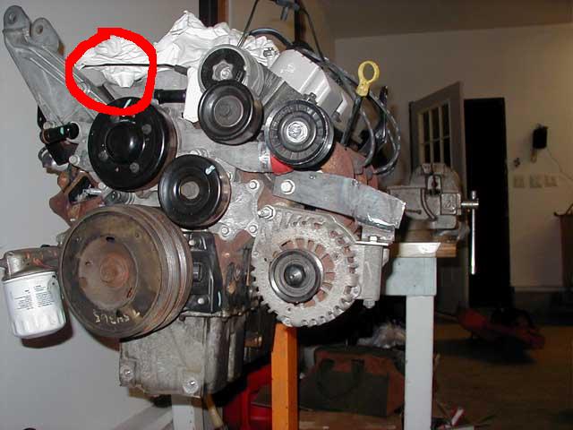
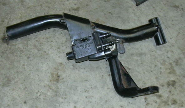
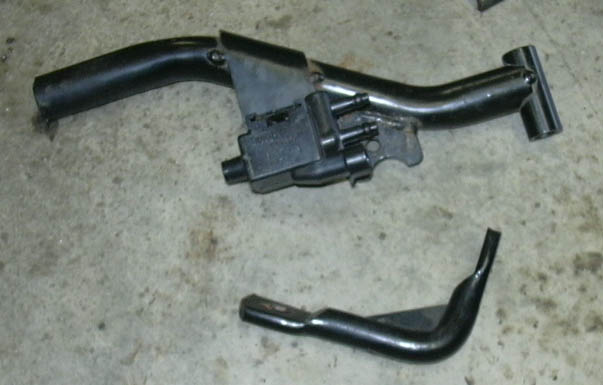
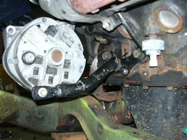
Below is a pic of how i cut everything up to make the parts i needed. There is allot going on in the pic so i will explain it out, sorry i have no in process shots but Mikee the action shot guy is not around cause gas is Thirty Billion Dollars a drop.. hehe!!

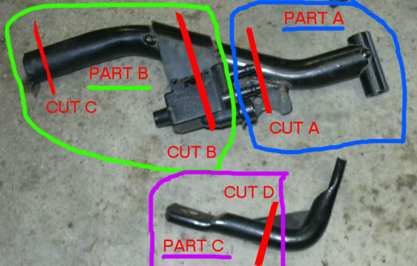
First off i took the large tube bracket and cut off ALL the other brackets on it, the sylonoid bracket and the U shaped steel piece near "CUT A". Normally the side near "CUT A" bolts to the blower, NOT anymore!!
Circled in GREEN and labeled as PART A is the new BOTTOM BRACKET. This will bolt to the hole in the bottom of the alternator (in back) and be welded to the super thick engine mount.
I then made the rest of the cuts on that tube (CUT B and C) to leave me with PART B. This will become the rear mount. However, after making the cuts you will not have any good way to bolt it to the alternator SOOOO... You take the other bracket piece and cut it at CUT D to make PART C.

Well the Lower Mount (PART A) is already done so lets forget that for now and move onto the REAR mount... It now will begin to read like assembly instructions for some back yard play set...
After cutting Part B out, which you need to do at CUT B and C (c - because there is a nut welded in the end of tube) you will then take PART C and make a cut at CUT D. Cut the angle OFF of PART C leaving behind just round stock with a flattened end with hole. NOW basically PART C just slides in the end of PART B.... make sure you put it in the end of PART B near where you made CUT C.

This will get welded in place but NOT YET because you need to make sure it all lines up right before tacking together.

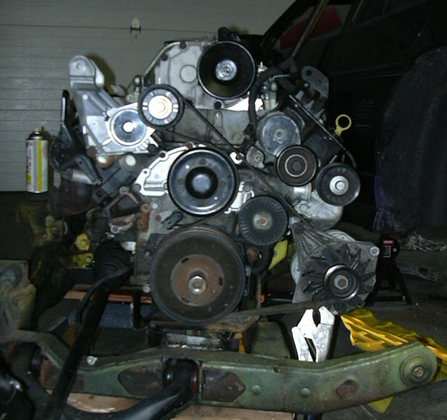
If you have the alternator properly spaced, I checked and RE-checked the belt travel and alignment. Should be perfect.....ish.

I basically have the top bolt in the block and through the long "wing" of the alternator. I then rotated it up so that it was close to the manifold heat sheild but DIDNT touch it. Also not so low that the belt hits anything (like itself at the water pump pulley which is close squeeze).

Then all you do is measure from center of bottom bolt hole to the engine mount to get length for PART A... now you know where to cut it at CUT A.

To get the length for PART B just measure from bolt hole in back of the alternator to the mount and subtract about an inch or so so that you have some room for PART C to stick out (flat spot with hole is there for a reason).

At this point with you would have everything cut to length... I bolted on PART A and then pushed it against engine mount to make sure it fit right and i had good angle on alternator (not to close to sheild and not to low for belt path). Then if all is well just TACK weld it GOOD into place. Remove alternator CAREFULLY and weld PART A to the mount.

I then put the alternator BACK ON and bolted it all down snug and checked fit and belt again...

Now you can figure out PART B... I bolted PART C to the alternator then slid PART B over top of it and lined it up where i wanted it on the engine mount... Did some looking around and clearence checks (dont want to block off ANY access to your engine mount bolts or it will never come off) LOL! Now just tack weld PART C to PART B. Remove the tacked assembly and weld it GOOD and SOLID! I then put the assembly BACK on the alternator, checked alignment onto the engine mount and tacked it to the mount NICE and STURDY....
Remove the alternator once again and weld the piss outta that tube to the engine mount...

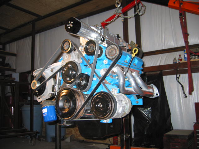
TA-DA thats it... hard core solid mounting.

Here are some pics and short descriptions of the setup...

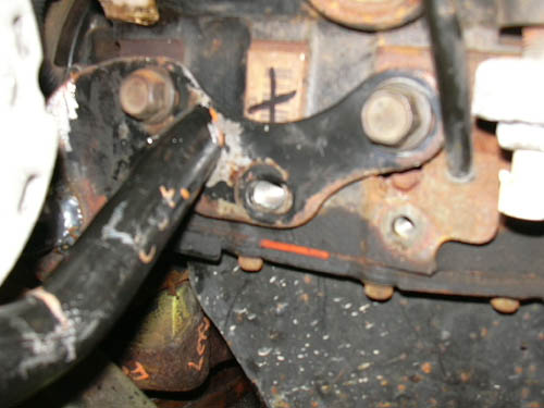
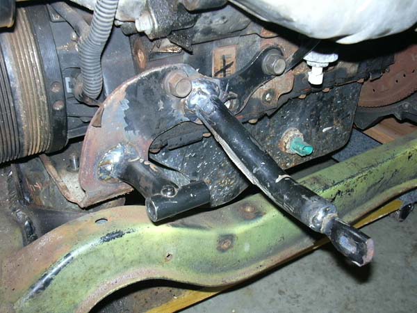
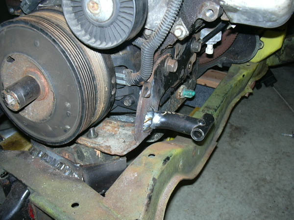
Here i am testing the position of the bottom mount... The bend goes towards the FRONT and so does the SHORT end of the tube where bolt goes...

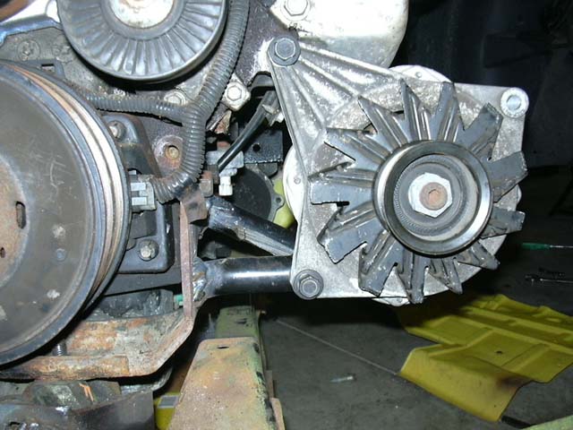
Here is the bottom mount welded into place...


MORE TO COME SOON... Just wait for the post!!

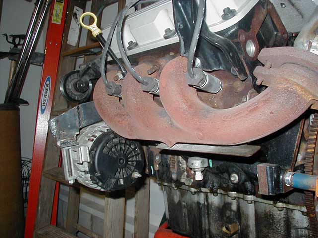
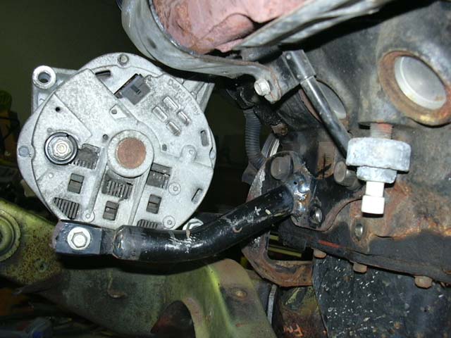
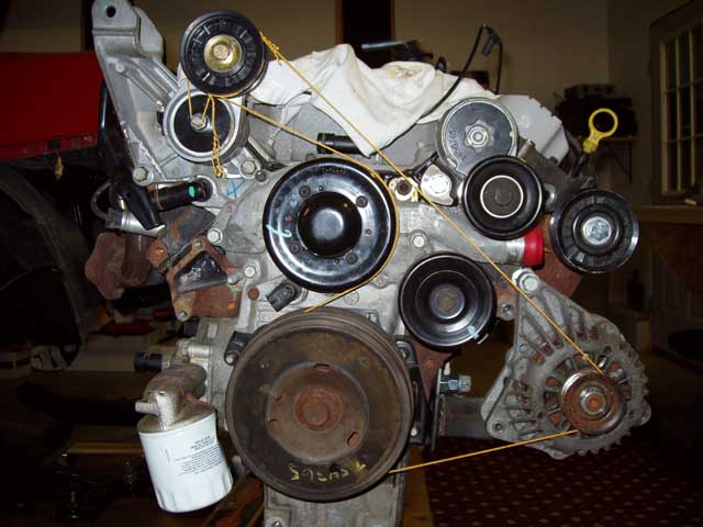
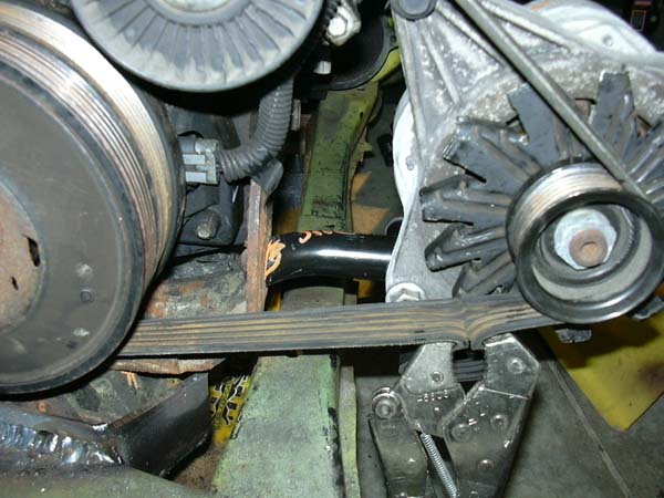
I dont have any pics of the back mount as a seperate PART B and PART C but here you can get the idea of how its fitted together... here i am lining up the location on the engine mount...

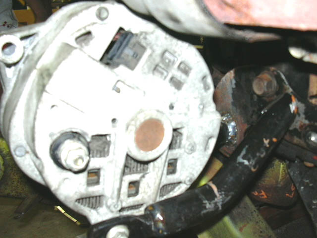
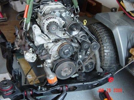
Here is a BAD SHOT but it shows about how you have to watch where you put back mount... there be bolts to dodge hehe!!

IP: Logged
The Fieromaster
Member
Posts: 4124
From: Painesville, Ohio USA
Registered: Jun 2001


Feedback score: N/A
Leave feedback


Total ratings: 104
Rate this member

Report this Post01-21-2006 01:20 PM Click Here to See the Profile for The FieromasterSend a Private Message to The FieromasterDirect Link to This Post

The Fieromaster

4124 posts
Member since Jun 2001
Here are BOTH mounts welded in place... they LOOK ugly now, but i have some more grinding and some painting to do before they are PRETTY hehehe!

Here are some pics of the alternator mounted in all snug... and i MEAN snug... i can stand AND bounce and she aint goin no where!!

(yeah i know this is before back was welded but you get the idea)

AND THE GRAND FINALLE.... The new completed belt rougting!!

.
.
.
.
.
Well thats how i did it, if you have any questions let me know. Here is a link to my FULL SWAP thread... https://www.fiero.nl/forum/Forum1/HTML/053213.html

Later...

------------------
"Raced That, Wrecked Better" ~In Memory Of Jesse Cesek~ 1980-2000
US Armored Cavalry - Fox 2/81 - Death By 120 - 1 Shot 1 Kill

3800 SuperCharged Series II Swap, ZZP Intercooler, Fastback Swap

IP: Logged
Raydar
Member
Posts: 41135
From: Carrollton GA. Out in the... country.
Registered: Oct 1999


Feedback score:    (13)
Leave feedback


Total ratings: 461
Rate this member

Report this Post01-21-2006 01:48 PM Click Here to See the Profile for RaydarSend a Private Message to RaydarDirect Link to This Post
Gotta envy you guys up in the frozen North who can survive without A/C.

------------------
Raydar
88 3.4 coupe...........

Praise the Lowered!
Read Nealz Nuze!

IP: Logged
anthony_86gt
Member
Posts: 494
From: Monroe, MI
Registered: Feb 2001


Feedback score: (1)
Leave feedback

Rate this member

Report this Post01-21-2006 02:10 PM Click Here to See the Profile for anthony_86gtSend a Private Message to anthony_86gtDirect Link to This Post
fieromaster how much room do you have between your alt and the firewall? that looks like it sticks out pretty far.

lyode, if i rotate it too much dont you think the belt will rub right where the water pump is? if you look in the last picture posted by fieromaster it looks like i might not be able to. my last option will be to get the style alternator that everyone else is using. but i dont know what year its off of. 96-98 ??? thanks for all the help guys, keep it coming.

IP: Logged
FastFieros
Member
Posts: 2698
From: Dallas Texas USA
Registered: Nov 2000


Feedback score: (2)
Leave feedback


Total ratings: 265
Rate this member

Report this Post01-21-2006 02:52 PM Click Here to See the Profile for FastFierosClick Here to visit FastFieros's HomePageSend a Private Message to FastFierosDirect Link to This Post
 
quote
Originally posted by Raydar:

Gotta envy you guys up in the frozen North who can survive without A/C.


I was thinking the same thing. No way in Texas is the AC getting deleted.

Loyde

IP: Logged
PFF
System Bot
RCR
Member
Posts: 4416
From: Shelby Twp Mi
Registered: Sep 2002


Feedback score:    (7)
Leave feedback


Total ratings: 102
Rate this member

Report this Post01-22-2006 07:35 AM Click Here to See the Profile for RCRSend a Private Message to RCRDirect Link to This Post
 
quote
Bob, what alternator are you using?

'98 GTP

Bob

IP: Logged
The Fieromaster
Member
Posts: 4124
From: Painesville, Ohio USA
Registered: Jun 2001


Feedback score: N/A
Leave feedback


Total ratings: 104
Rate this member

Report this Post01-22-2006 09:23 AM Click Here to See the Profile for The FieromasterSend a Private Message to The FieromasterDirect Link to This Post
 
quote
Originally posted by anthony_86gt:

fieromaster how much room do you have between your alt and the firewall? that looks like it sticks out pretty far.

lyode, if i rotate it too much dont you think the belt will rub right where the water pump is? if you look in the last picture posted by fieromaster it looks like i might not be able to. my last option will be to get the style alternator that everyone else is using. but i dont know what year its off of. 96-98 ??? thanks for all the help guys, keep it coming.

About 4 inches or so at LEAST to the heat sheild thats in there. Enough room to easily get my hands in there and root around if need be. No heat issues too because the stock manifold heat sheild and my exhaust doesnt route like stock Fiero. So there is nothing heating it up from underneath.

IP: Logged
anthony_86gt
Member
Posts: 494
From: Monroe, MI
Registered: Feb 2001


Feedback score: (1)
Leave feedback

Rate this member

Report this Post01-27-2006 08:29 PM Click Here to See the Profile for anthony_86gtSend a Private Message to anthony_86gtDirect Link to This Post
update:

will this setup work??? here are some pictures.

IP: Logged
FastFieros
Member
Posts: 2698
From: Dallas Texas USA
Registered: Nov 2000


Feedback score: (2)
Leave feedback


Total ratings: 265
Rate this member

Report this Post01-27-2006 09:38 PM Click Here to See the Profile for FastFierosClick Here to visit FastFieros's HomePageSend a Private Message to FastFierosDirect Link to This Post
 
quote
Originally posted by anthony_86gt:

update:

will this setup work??? here are some pictures.

Hey, thats pretty good. Humm, that tensioner and dogbone setup looks familar....

Looks great if that belt will clear like it looks with string on there.

Loyde

IP: Logged
anthony_86gt
Member
Posts: 494
From: Monroe, MI
Registered: Feb 2001


Feedback score: (1)
Leave feedback

Rate this member

Report this Post01-28-2006 01:49 AM Click Here to See the Profile for anthony_86gtSend a Private Message to anthony_86gtDirect Link to This Post
thanks loyde! thats what i was hoping to hear. i could swing the alternator out a little further if i have to, to allow for more room with the belts. but then again i dont want the alternator sticking out too far.

and loyde i shipped out my wiring harnesses to you yesterday.

IP: Logged
redfiero
Member
Posts: 177
From: Cleves, OH, USA
Registered: May 2000


Feedback score: (1)
Leave feedback

Rate this member

Report this Post01-28-2006 02:50 PM Click Here to See the Profile for redfieroSend a Private Message to redfieroDirect Link to This Post
I kind of went the other way with my alternator and would like some input. I kept it in the same position but have dropped it about 1/2". I currently have no spring loaded tensioner in the system. If I keep it the same, I'll need to make the alternator slide to tension the belt. I do have a few questions and am looking for comments.

1. Will dropping the alternator about 1/2" clear the decklid problem on a GT?
2. Will the aluminum dogbone bracket that came on the other side of the 98 GTP engine line up with the mount on the trunk wall?
3. Do I have enough wrap on the water pump pulley?

I think I'd like to mount the alternator solid and put a spring idler just below it. I have enough room I just need to get an idler.

I just had to take the water pump brackets apart today and look at the 3/16" or so hole in the stock aluminum bracket that connects the outlet of the intake manifold to the secondary inlet of the water pump that has been discussed in other threads. I removed the plug and saw what the fuss was about and have a few questions. Do all cars continue to circulate water through the heater core even when the heat is not on? Loyde, you would be a good person to answer the next part of this. On the intake, where does the coolant inlet come in in relationship to the radiator outlet on the tranny/firewall side? The outlet that goes to the heater core must be a secondary outlet to the one that goes back to the radiator on the other side of the engine. I'm wondering if the 3/16" hole is used to continue circulating coolant through all passages in the intake even when flow is shut off to the heater core? Can I tap the hole in the intake manifold and the one in the water pump and run a 3/16" stainless steel tube between them? Seems like the size will be small enough to force most of the coolant back to the radiator but will continue to allow coolant to circulate out of the intake.

All input is welcome!!

Thanks,
matt

IP: Logged
FastFieros
Member
Posts: 2698
From: Dallas Texas USA
Registered: Nov 2000


Feedback score: (2)
Leave feedback


Total ratings: 265
Rate this member

Report this Post01-28-2006 04:53 PM Click Here to See the Profile for FastFierosClick Here to visit FastFieros's HomePageSend a Private Message to FastFierosDirect Link to This Post
 
quote
Originally posted by redfiero:

I kind of went the other way with my alternator and would like some input. I kept it in the same position but have dropped it about 1/2". I currently have no spring loaded tensioner in the system. If I keep it the same, I'll need to make the alternator slide to tension the belt. I do have a few questions and am looking for comments.

1. Will dropping the alternator about 1/2" clear the decklid problem on a GT?
2. Will the aluminum dogbone bracket that came on the other side of the 98 GTP engine line up with the mount on the trunk wall?
3. Do I have enough wrap on the water pump pulley?

I think I'd like to mount the alternator solid and put a spring idler just below it. I have enough room I just need to get an idler.

I just had to take the water pump brackets apart today and look at the 3/16" or so hole in the stock aluminum bracket that connects the outlet of the intake manifold to the secondary inlet of the water pump that has been discussed in other threads. I removed the plug and saw what the fuss was about and have a few questions. Do all cars continue to circulate water through the heater core even when the heat is not on? Loyde, you would be a good person to answer the next part of this. On the intake, where does the coolant inlet come in in relationship to the radiator outlet on the tranny/firewall side? The outlet that goes to the heater core must be a secondary outlet to the one that goes back to the radiator on the other side of the engine. I'm wondering if the 3/16" hole is used to continue circulating coolant through all passages in the intake even when flow is shut off to the heater core? Can I tap the hole in the intake manifold and the one in the water pump and run a 3/16" stainless steel tube between them? Seems like the size will be small enough to force most of the coolant back to the radiator but will continue to allow coolant to circulate out of the intake.

All input is welcome!!

Thanks,
matt

Answer 1) Dont know, but I would say that your alt in that picture will not clear with only dropping it .5 . The 99+ alt is smaller, and I dont think even dropping it 1 inch would clear the GT rib in the decklid.

Answer 2) NO, it will not line up 100% with no modifications to it. OK, well, it also depends on your mounts and how the engine is set on the cradle. Lets say you are using WCF or Purple Reigns mounts, the dogbone bracket does not line up.

Answer 3) The water pump pulley belt wrap looks fine. RCR's however does concern me if his is getting enough bite on the water pump pulley. Been meaning to mention that RCR in this discussion.

As noted by Ryan, most all late model cars do circulate water in the heater core at all times and use doors to regulate the amount of heat that exits that area of the HVAC unit. There are some automatic climate control systems that still use a water gate valve. Most manual systems do not use water gates. The Fiero does not use a water gate, so coolant is moving in the system all the time.

You can tap the intake output and use it to the heater core. Its an odd size however for a NPT tap. You have to drill it out. I forgot what size I used. It was by request of someone that sent me a intake for the IC mod. I also got an intake from someone that tried to weld a -8 AN fitting, but they messed it up real bad and traded me the intake for another good one.

You can bypass all you feel the need to. I can say it is not necessary by experience and testing done here on many 3800SC installs, and by the answer I got from the GM engineer I asked what the hole was for.

There's another reason that engineers designed the intake output to heater core before the Tstat. GM use to have most heater cores on the side of the Tstat , that when you started the car, the heater core did not get hot until the whole engine was at 180 plus to open the Tstat. Once the Tstat was open, the coolant then fed the heater core and you got warm inside the car, but worse, the windshield would take forever to get the ice melted because the defrost would not get hot fast enough. In comes the great idea to put the heater core on the engine side that gets hot very fast. The water in the engine will heat very quick, and even only 100 degree water in the heater core is better than 40 degree water just sitting there waiting on the Tstat to open to release the water. So, now a days, the heater core gets the water that is in the engine right now always. My design with the low mount follows this design by getting the water from the engine all times right now. Tstat does not have to be open. Hence the pressure never builds behind the Tstat, it has the whole area of the tubes to the heater core and back, plus the 87/88 returns to the right side coolant tube and this is back pressure then to the radiator and the back side of the Tstat. The 85/86 has the relief at the water pump housing to the same method of relief to the radiator, and backside of the Tstat also.. What this all means is, IF there was extreme pressure, the radiator cap in the front of the Fiero becomes the relief valve, and dumps in the coolant recovery tank.

The alt is in no worse shape without a cooling medium than it was in the Fiero on a low mount setup like I make. Sure it does not get the benefits of the newer method of coolant circulation in the aluminum housing, but hey, we have alts still running on Fieros that quite old from what I have seen in working on these cars for people.

If you feel the need to include a 3/16ths line between the input and outputs, what you ask sounds like the way.

Loyde

[This message has been edited by FastFieros (edited 01-28-2006).]

IP: Logged
redfiero
Member
Posts: 177
From: Cleves, OH, USA
Registered: May 2000


Feedback score: (1)
Leave feedback

Rate this member

Report this Post01-28-2006 05:30 PM Click Here to See the Profile for redfieroSend a Private Message to redfieroDirect Link to This Post
Thanks Loyde! I very much value your opinion and expertise!

I'll probably end up plugging both the intake manifold and the water pump. Probably not worth the effort to run a small line.

When you do your low mount bracket, what do you do for the intake and water pump ports? Can you put a freeze plug in the water pump? Do you make the low mount brackets for sale or only with your installs?

Thanks,
matt

IP: Logged


All times are ET (US)

T H I S   I S   A N   A R C H I V E D   T O P I C
  

Contact Us | Back To Main Page

Advertizing on PFF | Fiero Parts Vendors
PFF Merchandise | Fiero Gallery
Real-Time Chat | Fiero Related Auctions on eBay


Copyright (c) 1999, C. Pennock