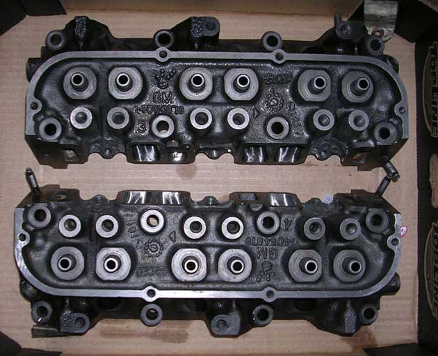
So, for the guys like me who ported the exhaust manifold only, you have less than 1/2 the required exhaust porting done.
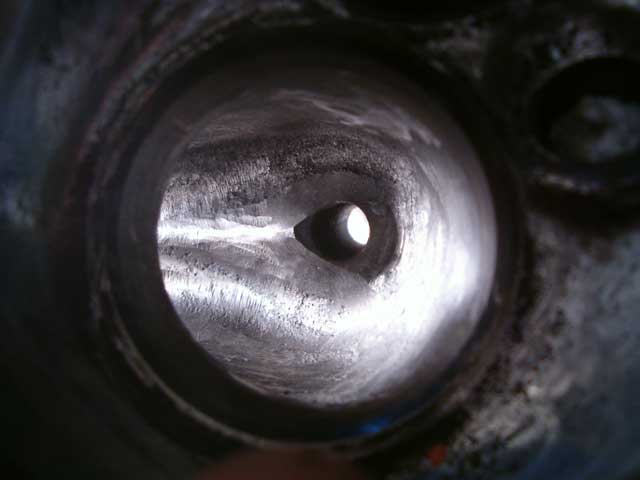
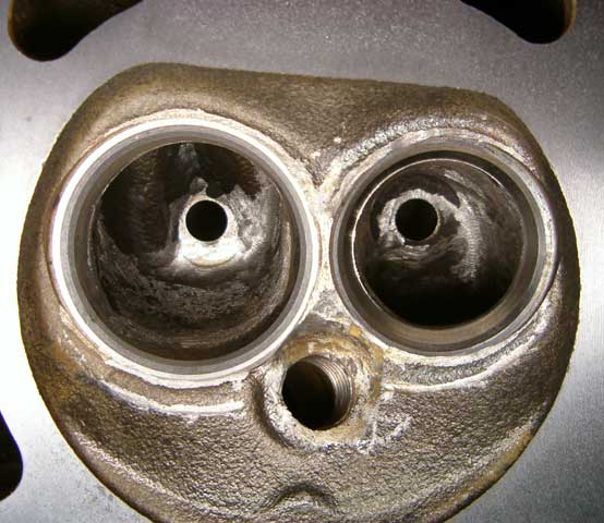
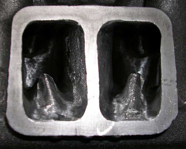
The exhaust can be safely hogged out. You want it smooth, like a mirror. The pic below does not look smooth but it is smooth to the the touch. Everything is polished with a dremel 120 grit flap wheel.
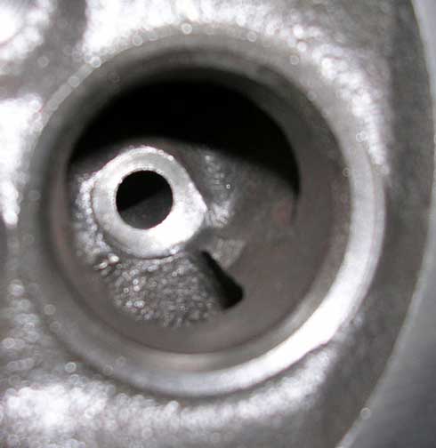
The ledges have to be hogged out, and the short side of the radius of the turn smoothed. You have to grind off quite a bit of the long side to get volume going past the turn.
I took the 1+1/8" measurement straight back to the curve.
more to come
[This message has been edited by Arns85GT (edited 03-12-2005).]
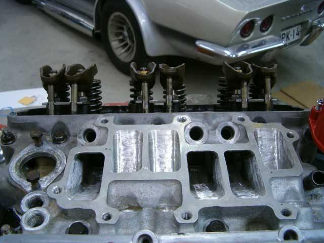
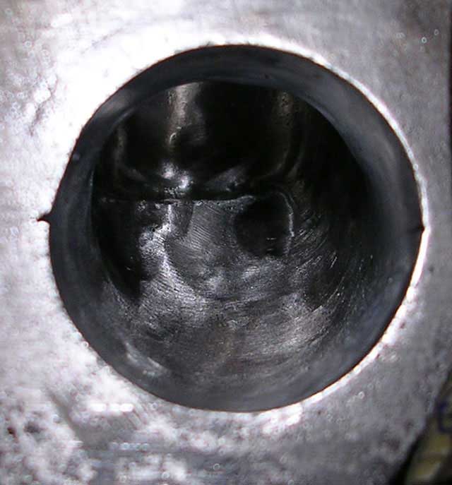
The intake is another story. The runners should be slightly rough. I used a white grinding stone supplied to me by Rubyredfiero.
Many thanks to Oscar. He is really very knowledgable.
The intakes are not all equal. I took the largest one, smoothed out the mold marks and roughed it. I then matched the other runners to it.
I left the fin in tact, but it is hard to work around it so they did get some grinding which was necessary given my skill level and the tools.
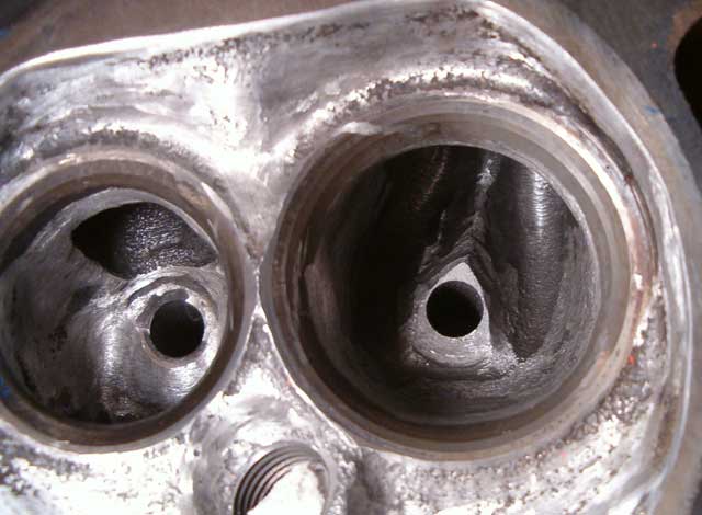
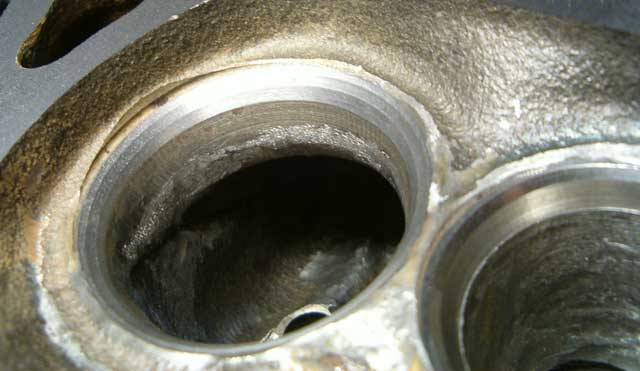
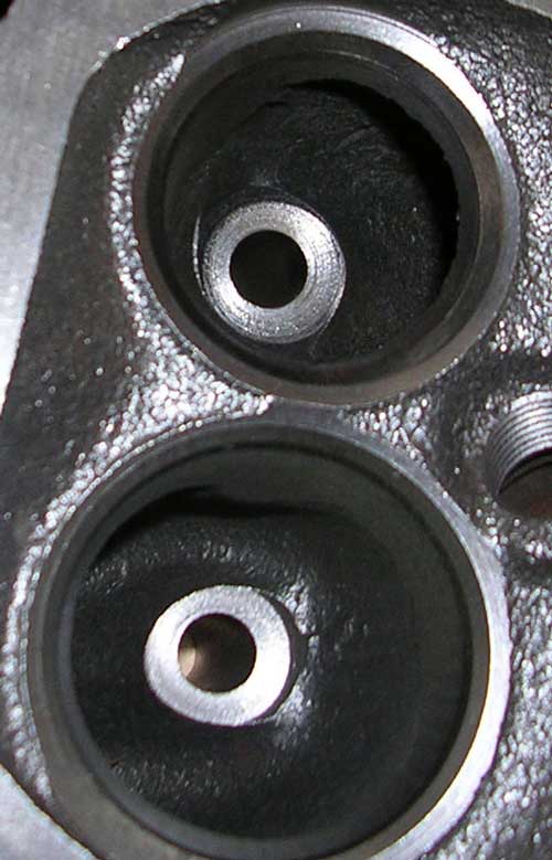
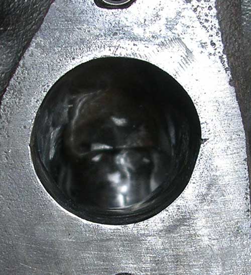
The intake bowls however, are smoothed with the dremel flap wheel. Smooth about an inch before the valve, but rough past that.
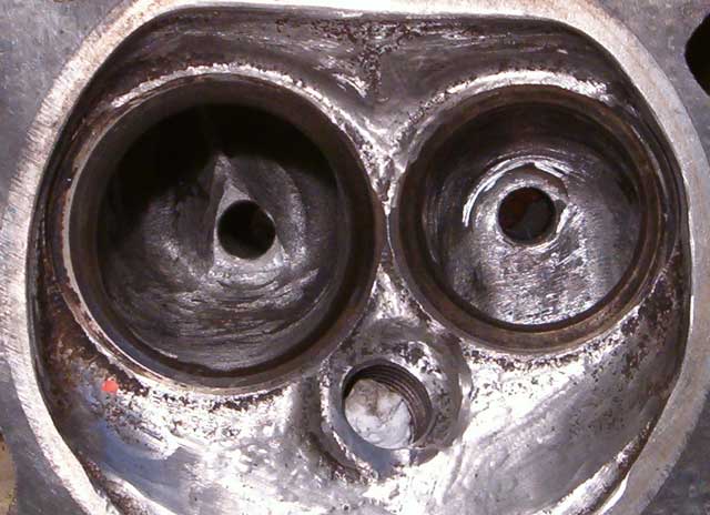
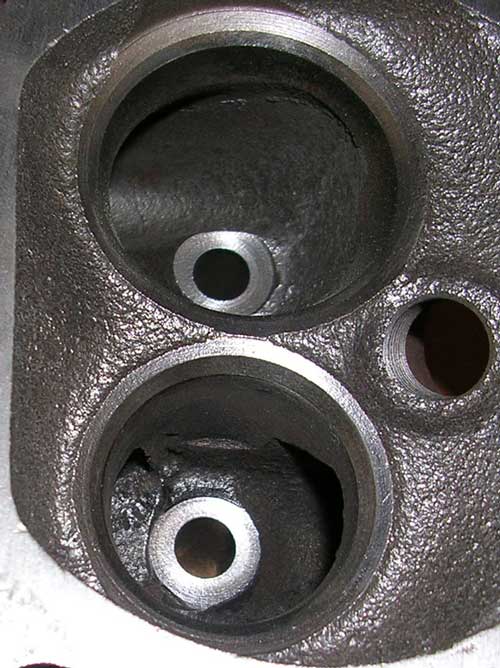
Notice the stock bowls again
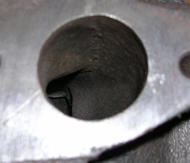
This pic is the middle cylinder. Notice the crossover hole for heating the intake manifold. There is a knob right beside the hole and it is pretty restrictive.
I thought about doing the knife edge on the fins, but decided against it.
If you examine the cross sections at various points, you will discover a trumpet effect.
What I did was try to keep that effect. A gradual openning up to a round pipe going into the valve.
You will see that the sides of the intake bowl are really hogged. That is to give minimum turbulence at the valve entry point.
The other issue is the Edebrock intake.
The Edelbrock intake has left side runners that are 2.5 cm X 2.5 cm. They are longer and narrower for more air speed.
The right hand runners are 2.5 cm X 4 cm. Hmmm......
So the heads which are in theory the same size are receiving different air volume/flow rates. What I did was to ensure the right side had 2.5 cm width the same as the intake runners. The height maxxed out to 3.5 cm vs the intake manifold at 4 cm. There is not much room to hog out the intake runners, and you really shouldn't . Remember the trumpet effect?
Now from the pics you can see my mistakes. This was the first time for me.
Anybody can do it.
Here are the tools.
A 3.8" drill, and a dremel with the extension wand.
Bits are
1/4 drive - 3/8" X 1" X3"double cut carbide burr (takes out alot of material) 1/4 drive - 1/2" X 1" X3"single cut carbide burr. (slower and smoother) 1/4 drive - 1/4" X 1/2" X 6"double cut carbide burr 3/8" dremel sanding drums 60 and 120 grit [edit] 1/4" dremel sanding drums 80 and 120 grit Medium dremel cutting stones 120 grit dremel flap wheels (2)
I have some buffing wheels and I am still toying with buffing the exhaust runners.
The machine shop will do the valves.
Anyway, point of the exercise is that anybody can do it and it. I hope this helps somebody.
------------------ Arn
[This message has been edited by Arns85GT (edited 03-12-2005).]
IP: Logged
11:59 AM
crzyone Member
Posts: 3571 From: Alberta, Canada Registered: Dec 2000
I'm just trying to remember off the top of my head, but I think I read somewhere that the bump in the exhaust port should be left in there. It was actually proven to flow more air with it left. Maybe someone else can chime in here and verify what I read or I'm just nuts.
You can experiment this way. Take a tube and blow through it. then create the same bump top to bottom, 1/4 of the volume of the tube with tape and some paper.
Blow again. More pressure right?
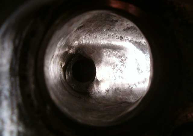
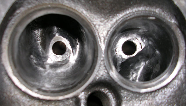
The bump on the intake splits the air flow to allow the air to go around the valve stem and create a swirl in the chamber.
No such action in the exhaust side. Notice how I nicked the intake bump when I was grinding. I could have done better.
Hope this explains a bit.
Arn
IP: Logged
12:22 PM
STRATOHACKER Member
Posts: 820 From: Columbus, OH U.S.A Registered: Jun 2003
Hey Arn, Looks like you got em done. My computor took a dirt nap and I had to go to the library to read e-mails. I am sorry I did not get a chance to reply to the e-mail you sent. I didn't want you to think I was ignoring you. You have pretty much done what I would have suggested anyway. There is one thing I would suggest on the exhaust ports and that would be to get a cross buff set from Standard Abrasives and use those to polish the exhaust ports. The cross buffs will give a much smoother surface than the flap wheels do. In reality though you are probably smooth enough. Any ideas when it will be back together? Richey
While I have not ground on my 2.8 heads--it runs just fine, so far--I spent a weekend in grinding on my Dodge 360 heads. The exhaust ports looked pretty much like your first photo, and I assumed these were just 'poor' castings. It was very gritty, dirty, and rewarding.
I agree it doesn't take much in the way of equipment, or time (hey--we mechanic--for fun!!), to improve head performance dramatically, since factory castings/parts are, if nothing else, of highly variable quality. ( Fiero exhaust headers, exhibit #1). I would encourage anyone with the tools, time, interest, etc., to go for it.
My 360 really pulls. I built it to haul my boat, and it probably puts out about 275 HP (40 over stock), with the torque coming on about the time the secondaries open up at 3500 rpm+. But man, does it burn fuel!! These head mods are not for economy engines!! These engines are more 'efficient' at moving air thru the engine, every rpm. And all that air includes fuel. Be prepared to pay at the pump for the power, whether you use it or not!!
Disclaimer: I'm thinking about sending my entire intake system--TB, both intake manifolds-- to Darrell Morse next summer for a 'little' work--well, $500 worth. And I've been told they'll fit on a 3.4 short block. : )
IP: Logged
01:55 AM
PFF
System Bot
Cajun Member
Posts: 1617 From: Youngsville, La., USA Registered: Dec 2003
PS. I got a couple of compressed paper dremel bits from Oscar and they seem to be 'putting the shine' on those exhaust runners rather well.
Well, here is the result of giving up about an hour with the compressed paper dremel head.
This compares to the flap wheel result.
So, it has been double cut carbide burr - single cut carbide burr or medium grind wheel - 120 grit dremel drum sander - 120 grit flap wheel -then compressed paper dremel wheel.
I am happy with the result. Thanks for the bits and tips to Rubyredfiero
Arn
IP: Logged
05:35 PM
crzyone Member
Posts: 3571 From: Alberta, Canada Registered: Dec 2000
You can experiment this way. Take a tube and blow through it. then create the same bump top to bottom, 1/4 of the volume of the tube with tape and some paper.
Blow again. More pressure right?
The bump on the intake splits the air flow to allow the air to go around the valve stem and create a swirl in the chamber.
No such action in the exhaust side. Notice how I nicked the intake bump when I was grinding. I could have done better.
Hope this explains a bit.
Arn
Gotcha. I knew there was a bump that was important somewhere, didn't know if it was intake or exhaust. Thanks for clearing that up.
If you're out for the Grand Bend cruise this Saturday, you can see for yourself.
I don't know if the jetting is quite perfect, but, when I start it, the lamp in the master bedroom rattles. You know, like when a jet flies a little too low?
At idle you can hear the air hitting the bottom of the T joint in the exhaust. Kind of a Pam-Pam-Pam metal sound. That sound disappears at about 1000 rpm and it settles into a nice roar.
When I get on the throttle, I have to respect the clutch for now so I haven't dumped it, but it pulls real strong to 6000 rpm.
I tried a pass on the freeway from 100 kph to 140 kph and it got there before I got by the car in front. I expect it is better than it was.
Arn
IP: Logged
03:12 PM
Pyrthian Member
Posts: 29569 From: Detroit, MI Registered: Jul 2002
If you're out for the Grand Bend cruise this Saturday, you can see for yourself.
unfortunatly, I'm just getting started on replacing my trans. split the case on my 4-spd muncie but, maybe I'll take out the family sedan, and take the wifey camping at the Pinery, and sneak out to meet you all. I miss the Grand Bend cruise every year.... seems I'm always doing something to my car in the early season....cradle dropping is a yearly event in my garage...ARG!
IP: Logged
03:26 PM
May 27th, 2005
Will Member
Posts: 14307 From: Where you least expect me Registered: Jun 2000
Originally posted by Arns85GT: If you examine the cross sections at various points, you will discover a trumpet effect.
What I did was try to keep that effect. A gradual openning up to a round pipe going into the valve.
You mean tapering down to the valve like a funnel? Increasing cross section as you go toward the valve will slow the charge down and reduce low RPM torque.
You mean tapering down to the valve like a funnel? Increasing cross section as you go toward the valve will slow the charge down and reduce low RPM torque.
That is not the way it is Will. The bowl is bigger than the runner. The runner flares out to match the bowl size. The air swirls before it moves down to the valve openning. It is a trumpet shape, sort of. When you port, you first hog out your bowl. You smooth the sides down about an inch and smooth out the walls to create clean air flow. You then blend the bowl to the runner.
This way, you keep everything proportional. The runner creates air speed because it is smaller than the bowl. The cylinder is way bigger than both of them, so the suction at the valve empties the bowl, hopefully in an even manner so the air is pulled more or less evenly around the valve. The runner creates the speed, and the bowl finalizes the mix.
I hope this explains.
Arn
[This message has been edited by Arns85GT (edited 05-27-2005).]
Nice contours. You have uneven surface on the exhaust bowl wall, but you are close. It looks like you can take more out of the sides of both bowls for sure. I can't tell from the pics, but you need a smooth transition from the intake walls to the bowl walls. The bowl should drop right off, right below the valve seat, and have a clean, smooth run to the bottom. (Don't nick your valve seats though)
Also, the exhaust bowl should be shiny smooth. The closer to glass the better. The reason I was told, is that carbon doesn't stick to the smooth surface and the air doesn't tumble on the smooth surface for quicker evacuation.
You will want to polish the intake bowl as well.
You're well on your way for the good set to be real nice. Nice accomplishment.
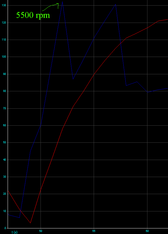
Work done: "ported" heads, ported stock manifolds, matched intake and Edelbrock performer cam (204/124 deg @ 050). ECM should be pretty stock with disabled EGR. Things to correct are that TPS will never go above 85% and fuel maps are a bit lean. I don't think it's a good idea to correct them before replacing injectors. Not a bad result, I think.
Your work looks pretty good. Just to recap...The exhaust SHOULD be polished. The Intake SHOULD NOT be polished. The reason being, if the intake ports are polished it leads to "puddling" of gas, which is bad. You want a little bit of roughness to keep the air/gas turbulent to improve atomization.


 You know, like when a jet flies a little too low?