WORK IN PROGRESS... . . . . . . . . . . . . . . . . . . . . New, the fiero clutch system worked satisfactory. Now, 20 year old parts and simple wear from use is taking it's toll. First we'll look at the mechanical problems then we'll look for leaks.
The clutch pedal is the first part of the equation.
There are two problems that can occur with it. Most of this has already been explained by Archie here www.v8archie.com/arch6.htm (along with the step by step procedure for replacing the pedal. I followed it myself the first time I did one.) I'll ad-lib to it a bit, but this is mostly his work.
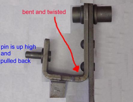
This is an aluminum pedal:
Notice how the "U" shaped bracket is bent to where it is closer on the top as opposed to the bottom. When this happens the left part of the U bends in three directions: Towards the driver, to the right and up closer to the fulcrum.
This causes two complications: It now has a shorter stroke because the pin the banjo shaft fits on is closer to the fulcrum. And the pedal pad can hit the floor before the master cylinder is bottomed out. A good sign of this is if you clutch pedal is not higher than your brake pedal.
The second thing to look for is excessive play from wear or missing bushing between the pin and the eye of the banjo shaft.
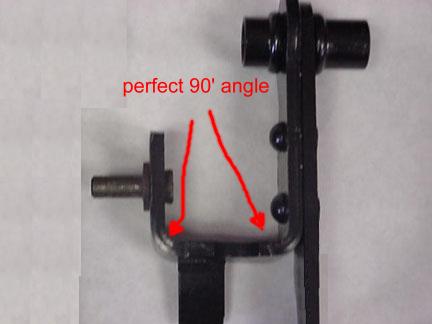
This is a steel pedal:
They are painted black and don�t bend very often but you can still have a problem with slop between the pin and the banjo eye.
You have two options here. If the U is bent more backwards than up, Rodney�s adjustable banjo will help. www.rodneydickman.com/n90.html If the U is bent up a lot then change the pedal, part # 66423 from www.fierostore.com
[This message has been edited by buddycraigg (edited 06-05-2005).]
IP: Logged
09:45 PM
PFF
System Bot
buddycraigg Member
Posts: 13620 From: kansas city, mo Registered: Jul 2002
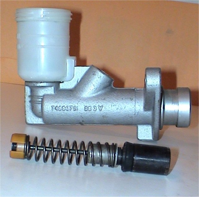
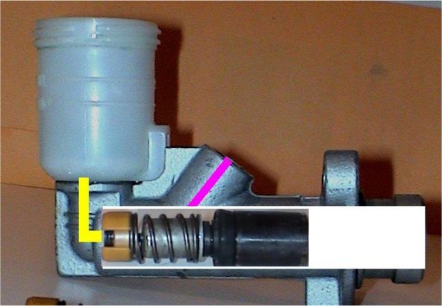
There were two clutch master cylinder designs used. First generation was cast aluminum and the line connected near the back 84-85. Second generation was tube steel and the line connected near the front 86-88. Both had 11/16" bore and used a similar banjo rod.
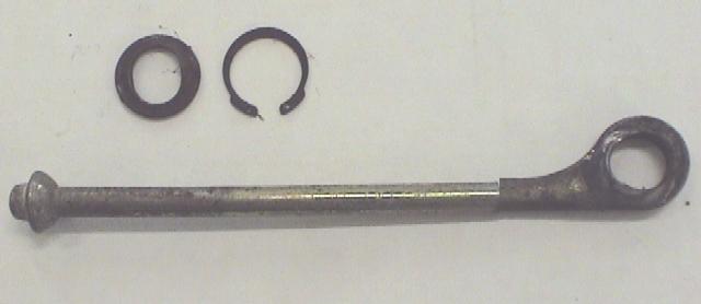
The left end of banjo rod is convex. And meshes with the back side of the master cylinder piston as it is concave.
There is a snap ring and washer in the back side of the master cylinder bore to keep the banjo rod and the rest of the internal parts from falling out.
Originally from the factory the clutch pedal has a spring that will return it to the up position. Pulling the banjo rod until it stops on the snap ring.
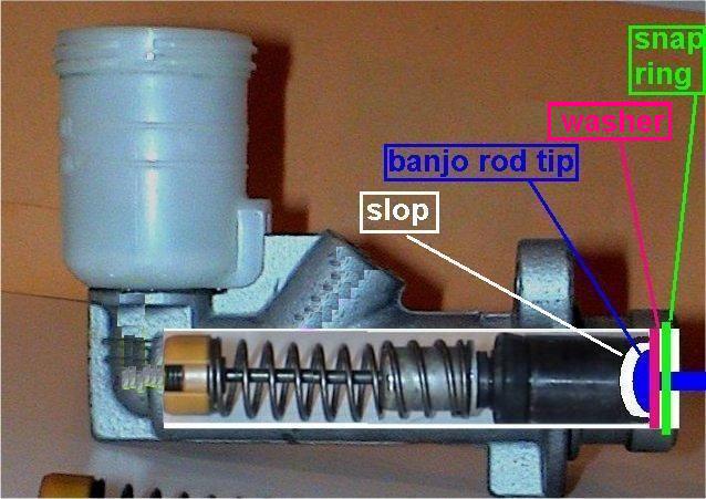
in these next pictures you will see a problem that I have found on every 84-85 that I have worked on with clutch problems.
When the pedal pulls the banjo rod against the snap ring there is slop between the convex end of the rod and the concave portion of the piston. The pedal can be depressed 1/4~1/2 inch before the rod come in contact with the piston.
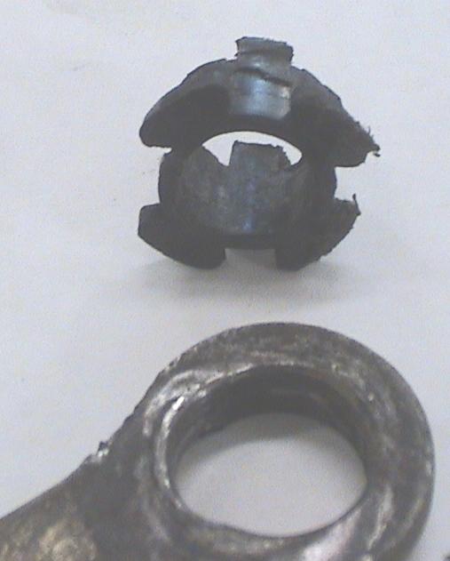
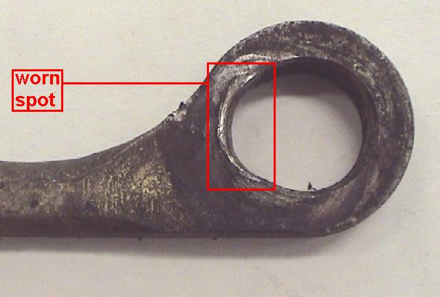
The eye of the banjo rod can develop wear or (if applicable) the bushing can fracture and fall out. Causing the pedal to have to be depressed even further before the rod starts to contact the piston.
Add all of these up and you can have 1" of pedal movement before the master cylinder starts to do anything.
This would be a case where Rodney�s banjo rod would help.
While you�re there make sure the eye is pointing up. This is how I remember which way it�s suppose to be. (I�ll modify my thought process a bit to be politically correct) imagine you had a basket ball in your shirt pocket. If you fell over, you would just bounce around until you looked like the letter �P� laying on it�s flat side.
[This message has been edited by buddycraigg (edited 06-05-2005).]
IP: Logged
09:47 PM
buddycraigg Member
Posts: 13620 From: kansas city, mo Registered: Jul 2002
I will start with the first generation master cylinder (cause it was first ) We need to know the parts inside before we can understand how they work together.
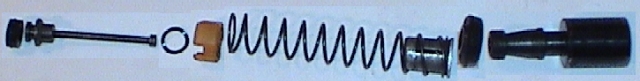
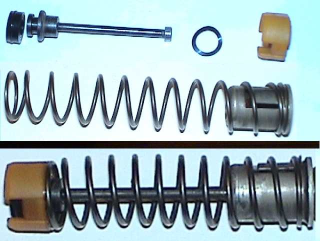
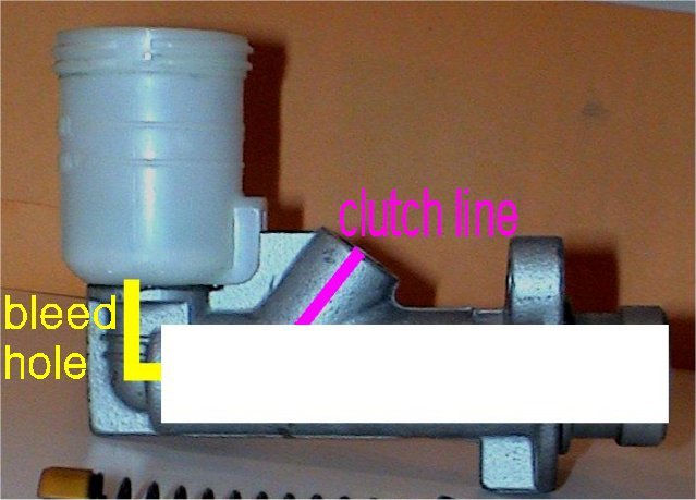
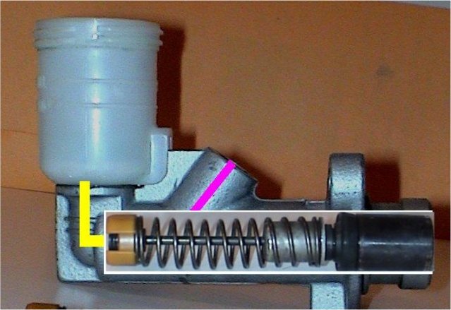
I haven�t seen these parts named in any book so I�ll give the pieces names that are logical to me. Starting left to right we have: Bleed off seal Bleed off pin (notice the shape of a nail head on the right side) Spring washer Bleed off cup Bleed off spring & Lock Piston seal Piston
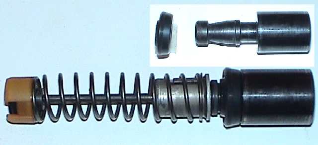
The bleed off seal is attached to the pin. This pin assembly goes through the spring washer, bleed off cup, spring, and finally the nail head is trapped in the lock. The spring holds the sealing end of the pin and spring washer recessed in the cup. These parts complete the bleed off portion. It allows the throw out bearing to float freely rather than maintaining contact with the pressure plate.
Although the bleed off valve HAS to function correctly for the system to work. Lets move on the real back bone of the master.
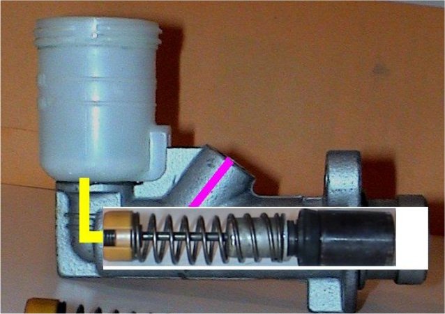
The piston seal is attached to the piston. This piston assembly is then trapped in the back side of the Lock. This completes all of the moving parts of the master cylinder. MINUS one important part� the fluid!
[This message has been edited by buddycraigg (edited 04-25-2005).]
IP: Logged
09:48 PM
buddycraigg Member
Posts: 13620 From: kansas city, mo Registered: Jul 2002
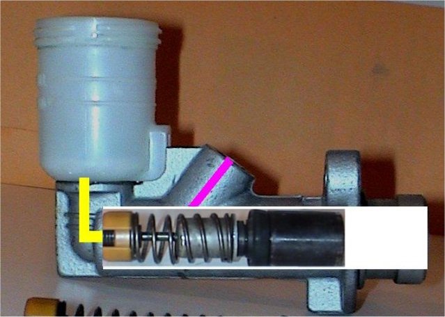
Now things get busy. You foot steps on the pedal. The pedal pushes the banjo rod. The banjo rod pushes the piston. The cup bottoms out in the master cylinder bore, depressing the spring, allowing the pin to float free.
The fluid starts to escape out the bleed hole AND the clutch line until there is positive pressure in the line going to the slave. The fluid cannot over come the pressure in the clutch line because of the slave, arm and pressure plate. The fluid stops flowing towards the clutch line and flows towards the bleed hole faster. This flowing motion pulls the free floating pin/seal assembly against the bottom of the bore. Sealing off the bleed hole. The fluid starts to pressurize the clutch line. The hydraulic pressure increases as the fluid fights for an escape. Thus increasing the sealing abilities around the bleed hole.
Finally all of the fluid moves towards the clutch line.
[This message has been edited by buddycraigg (edited 04-25-2005).]
IP: Logged
09:49 PM
buddycraigg Member
Posts: 13620 From: kansas city, mo Registered: Jul 2002
Another write up coming soon. I wanted to commit myself (to doing this project, not to a hospital) Thanks to the learning curve from doing the headlight rebuild I wanted to be able to get all of the information in the first few posts. Like if something new develops. So I have started the thread and grabbed the first ten posts to edit over the next week or so.
I�ve been hoping to design a good "pull" cable system for a while but haven't really gotten it off the ground, so I�ll just work with stock hydraulics at this time.
I used to rebuild hydrostatic transmissions. Always thought they were super cool. And enjoy playing with hydrostatic theory and math.
Did you know that Honda is in the Guinness book of world records for having the smallest hydrostatic transmission on their self-propelled walk behind lawn mowers?
------------------ Buddy Craigg - there are two "G"s in my last name Ling = 84SE-Modified Julia C = 85GT stock (kinda) Ivy = 67 Pontiac Catalina KCFOG
IP: Logged
10:08 PM
PFF
System Bot
buddycraigg Member
Posts: 13620 From: kansas city, mo Registered: Jul 2002
a pull cable setup would not be difficult considerting you can already buy the arm and bracket off other FWD gm cars - when i bought a replacement tranny i had to pull one of f- i think it was an isuzu out of a cavalier.
then a custom length cable run next to the throttle cable - a little bracket in the dash going to a bolt that you drilled into the clutch pedal arm and you are done. ---
or you could run it outside the cabin - have the clutch pedal pushing a swing arm in the middle (pivot on one end cable on the other) actually I like this idea more.. mmmm cable clutch
IP: Logged
09:15 AM
tesmith66 Member
Posts: 7355 From: Jerseyville, IL Registered: Sep 2001
Been putting a lot of thought into a cable setup. Evan have a plan cooked up for using a push cable that will employ the factory pedal, arm and mounts. I'll dive in and do it when (notice I didn't say if) my hydraulic system fails.
------------------ 1986 SE 350 V8
[This message has been edited by tesmith66 (edited 04-22-2005).]
Been putting a lot of thought into a cable setup. Evan have a plan cooked up for using a push cable that will employ the factory pedal, arm and mounts. I'll dive in and do it when (notice I didn't say if) my hydraulic system fails.
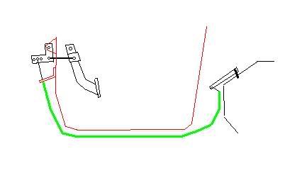
problem with a direct push-pull cable setup is you don't get the mechanical advantage (leverage) as stock on the clutch arm..
on the pull cable setups the arm is about twice as long as the fieros
a quick sketch of a potential adjustable setup you would run the cable right where the clutch hydraulic line runs right now
EDIT: now you have goen and done it - since i would have to modify my clutch arm to get it to work on the 3.4dohc anyways now i'm thinking about just measuring and fabbing up a cable system
[This message has been edited by Kohburn (edited 04-22-2005).]
IP: Logged
09:36 AM
tesmith66 Member
Posts: 7355 From: Jerseyville, IL Registered: Sep 2001
the more i think about it the more i like the idea.. I was also planning to put sealed rubber boots on the ends of the cable with lube inside - should never freeze up and I was also thinking of doing a reduntant system with multiple cables like what you can get from a bike shop.. that way if one ever broke somewhere you could get a new one cut to length in almost anay town in america
i can fab up a bracket to hold the belcrank and the cable(s) that will bolt right to where the slave mounted..
i may look for a fwd gm pull arm - or just modify the stamped steel one i have..
then make a tranny bracket to hold the other end of the cable.. taday - could probably make and mount everything necessary in a day the first time around - maybe i should sell cable clutch kits
Flip the arm on the transaxle over and pull it from the same side the slave cylinder pushes from. That will significantly shorten the cable. You could also modify the pedal to accept a mustang quadrant so the bellcrank wouldn't be necessary. The mustang quadrants are readily available on the aftermarket.
There are lots of places online that make custom cables.
IP: Logged
04:26 PM
buddycraigg Member
Posts: 13620 From: kansas city, mo Registered: Jul 2002
my thought was to leave the arm where it is and cut a slot in the socket the pushrod goes in to. attach the inner cable to the bellhousing and have the outer cable housing set in the socket. it would work simaller to our parking brake cable setup.
i wasn't planning on starting a thread about how to fabricate a cable clutch system, but what the hell...
------------------ Buddy Craigg - there are two "G"s in my last name Ling = 84SE-Modified Julia C = 85GT stock (kinda) Ivy = 67 Pontiac Catalina KCFOG
IP: Logged
05:22 PM
Apr 25th, 2005
buddycraigg Member
Posts: 13620 From: kansas city, mo Registered: Jul 2002
When going to a purely mechanical (cable) clutch, how are you going to mimic the full travel of the clutch pedal that is now achieved by using hydraulics? In other words, Mechanically, 1" of travel on the pedal will result in 1" of travel of the clutch release lever, meaning all the clutch engagement/dis-engagement will happen right near the top of the clutch pedal movement. 'That', will take some getting used to.
I've also run into problems on 2 different non-Fiero vehicles where the firewall the cable mechanism is attached to cracked due to the stress on it. Had to weld the whole thing back in.
Good write-up Buddy. Lookin fowd to seeing how this works out.
[This message has been edited by maryjane (edited 04-25-2005).]
When going to a purely mechanical (cable) clutch, how are you going to mimic the full travel of the clutch pedal that is now achieved by using hydraulics? In other words, Mechanically, 1" of travel on the pedal will result in 1" of travel of the clutch release lever, meaning all the clutch engagement/dis-engagement will happen right near the top of the clutch pedal movement. 'That', will take some getting used to.
I've also run into problems on 2 different non-Fiero vehicles where the firewall the cable mechanism is attached to cracked due to the stress on it. Had to weld the whole thing back in.
Good write-up Buddy. Lookin fowd to seeing how this works out.
there will be no more force on the firewall with a cable than with a hydraulic cylinder - and the clutch would release the same its just using flexible metal instead of fluid..
I wanted to use a belcrank for a couple reasons - 1 being adjustability, the other being that inside the cabin the car doesn't change AT ALL -- all you would have to do is replace the clutch arm ont he tranny with a pull arm.. bolt on the cable bracket.. pull off the clutch line and run the cable in its place.. remove the master cyll and bolt in the bracket with the bellcrank.. and adjust for a good engagement point.. done
doesn't get much easier than that
IP: Logged
08:32 AM
buddycraigg Member
Posts: 13620 From: kansas city, mo Registered: Jul 2002
Be aware that the "improved" steel clutch pedals bend too - I know of two examples. They're much better than the aluminum pedal in this regard, but they still bend...
Be aware that the "improved" steel clutch pedals bend too - I know of two examples. They're much better than the aluminum pedal in this regard, but they still bend...
And on the dreaded aluminum pedal the "U" bracket that actually bends is steel. I don't think it's the fact that the pedal is aluminum. It just that these pedals are the oldest. Bent brackets can be bent back. Just need a decent size vise and about a 16" crescent wrench.
IP: Logged
10:25 PM
sanderson Member
Posts: 2203 From: corpus christi, texas, usa Registered: Sep 2001
You're on a good track here. When we get around to the second generation master cylinder which in my eyes was a giant step backwards I'll chime in with some opinions


 )
)