I think you might find that where you�ve moved your hinge to is going to be right where you want to put one of those engine dogbone mounts. However, you can change the mounting angle on the dogbone, so it goes under.
I really didn't plan on mounting a dog bone there. With 4 solid motor mounts and a dog bone on the drivers rear of the engine, if that engine moves, it deserves to! In all seriousness, it doesn't conflict with anything I had planned for that area.
Hi All, I have been building a 1987 fiero GT for 3 + years,I hope to be able to help anyone who so desires to build your Fiero, in any way I can, I hope you will all do the same. Caddyrocket has taken a very good project. I have had more than 20 fieros in various states of ruin. I have two and a half at this time. I traded a 1986 fiero that had a 1993 Grand Prix 3.4 DOC,24 valve,with the getreg 5 speed. The most fun car I have ever driven, including a couple vetts, mustang, small block chev in a 1957 MGA, a corvair power VW and the list goes on. If Caddyrocket will send me information on how to post pictures I will try to explain, I hope we can all help each other. My 1987, I have install the Northstar with twin Turbos, and twin innercoolers, or after coolers if you prefer. I have a wide tract front suspension with poly on all cornners, suspension is chrome, and I have added Power steering. I have a Modified 1988 rear suspension that has poly on all corners. I can tell you how to make that modification. Except for machine work I have done all my own work. I have a 80 gallon compressor, and various air tools, angle grinders, drills , nipplers, sisors,sawall and many more. You will need a lot of tools, don't forget the chop saw. If your married I hope you have a good wife as I do. Your Hobby, will be a lot of fun. Poly bushing, front & rear suspension, comes from Held motor Sport. Axles I had cut 3/8 inch off each end, and had machine shop cut for the C clips. Make sure to clean with slovent before repacking. Nasty job. Moser company does axles, they may take more are less off. There is a young guy I met that has done Two northstar conversion, I will contact him and see if he will offer any help, He is very good mechanic and teacher. I have to figure out how to post pictures, so I can explain. F40man Back to the Northstar I have a drop out motor 1998 with auto trans CHRF intake& valve covers. I'd like to show how I got started.
quote
Originally posted by caddyrocket:
Put an hour in on the car tonight. Holiday insanity is in full swing here so it's difficult to find time but I got the passenger side decklid mount complete. Here are a few pics of the hinge and mount modifications.
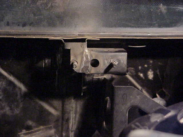
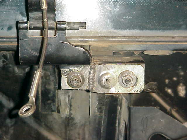
Here is the hinge mount. Basicly all I did was cut the bottom section of the hinge mount off about 3/8in below the top bolt. I cut some of the back off which allowed me plenty of space to fit the lower bolt which was to become the right hand bolt. Then I squared it up and welded the remainder of what was cut out to the side of the bolt. I've left it loose for now incase I need to tweak the whole mount but once I'm completely satisfied with the install, I'll take the new right hand bolt section to the firewall to give it a little structure. I really don't think these need much reenforcement as they aren't going to see much stress but it will make things more solid which is never a bad thing.
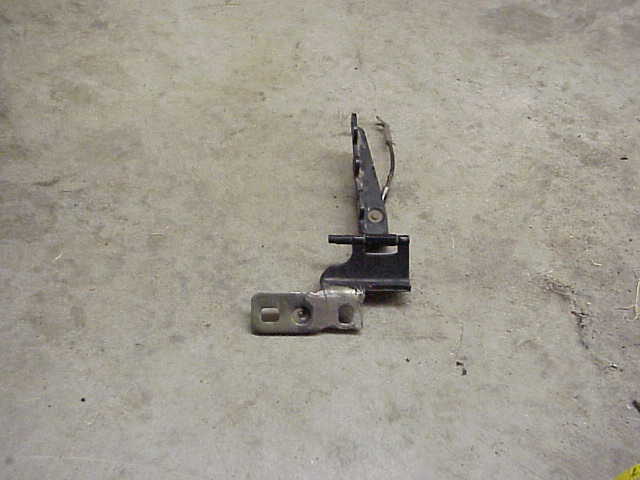
Below is the modified hinge. Modified in somewhat the same manner as the mount, I measured and cut off the bottom section and welded in onto the side. What looks like a little crack on the top of ground area is just the remainder of the weld that was ground down to it could mount flush.
This is the front side of the new hinge.
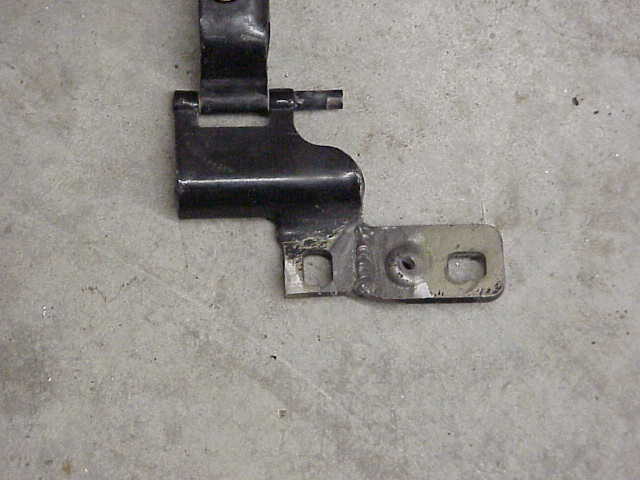
Here is the hinge installed on the mount. I measured between the two bolts on the decklid itself and it measures about 27.75 inches. This new passenger side hinge will have no problem mounting the decklid even and level.
This was a pretty easy part of the project but it turned out well and I'm happy with it. The mechanical fabrication peice of this is showing some light at the end of the tunnle finally. The electrical peice coming up next is going to be a pleasent PITA for sure.
IP: Logged
03:50 PM
RCR Member
Posts: 4454 From: Shelby Twp Mi Registered: Sep 2002
If Caddyrocket will send me information on how to post pictures I will try to explain, I hope we can all help each other.
F40man: There's a "Pennock"s Image Poster" (or PIP) icon at the bottom of all pages. Click on that and follow the instructions. By your name, sounds like you have an F40 rebody. Looking forward to seeing your pics.
Bob
IP: Logged
04:34 PM
RCR Member
Posts: 4454 From: Shelby Twp Mi Registered: Sep 2002
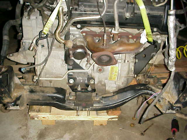
Tonight marks the end of major combat with the engine cradle. I opened up the bolt holes for the new engine mounts and welded in some steel tubing for support. I ground the welds flush and drilled out any welds overlapping into the tubes. The tubes I used are galvinized mild steel tubing from Lowes incase anyone is ever looking for it. This should work fine for reenforcing bolt holes and such.
I haven't decided what I want to coat the cradle with. I had planned on powder coating it but that is going to take to long. The weather has been very kind to me so far this winter but my wife is wanting her side of the garage back! I better get the engine permanantly mounted in the car before the first big ice storm hits! That said I have investigated a number of coatings. I'm considering the use of a rubberized coating or perhaps a good thick coating of primer and matte black paint. I am going to try out the rubberized stuff and see if it does the job.
I'm also going to fill the holes in the cradle with some expanding foam to try to prevent so much sand, dirt, and rocks from getting in the cradle. Seems like I've dumped 1/2 the cars original weight out of it over the course of this project!
Tonight was a night for misc peices. I cut out and clearenced the front cross member so the AC compressor can be retained in it's stock location. I ran out of disk space on the camera so I didn't get a pic of that but it's just notching the cross member. I'll test fit it and take some pics when I weld in the support and grind it.
I decided to coat the engine mounts I made in a rubberized coating and paint the cradle. Below is a pic of the new front engine mount before painting. Both mounts were designed to replicate the originals minus the reduction in height. You can see the angle and bolt hole alignment better than in previous pics. The right side will face the front of the car when complete.
Here is a top view of the rear engine mount. The center bolt hole will face the rear of the car. It is painted with the coating already. My hope is that the coating will provide enough isolation to reduce any minor vibration that might be common although I've heard everyone else who is using solid mounts have no problems with it. It will also prevent any metal to metal contact which could create noice and possible exposure to corrosion. Pic sucks, sorry. I had just painted it when I realized I wanted to snap a picture of it first.
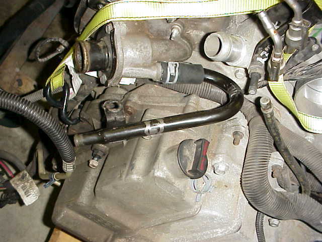
The pic below is the newly modified heater core outlet line. Again, ever forgetful, I didn't snap a pic of the line before it cut it up. It snaked it's way from the front of the engine around to the back along the top of the transmission. Using the bends in the original line, I cut what I didn't need out and welded it together in the candy cane looking shape. The pics below give an idea of the orientation I used which put the pipe right where I intend to route the heater core lines.
Finally, here is a pic of it installed somewhat in the orientation it will be assembled in. there is a mounting bracket on there that will be modified or moved so I can bolt it down.
Tomorrow I hunt for Pontiac 6000 uprights (spidles, knuckles, hub carriers, whatever the person on the other end of the phone wants to call it). I might get together a machinist buddy and fabricate my own for the hell of it. Depends on how much hassle the salvage yards give me. Just for kicks, I called a local Pontiac dealer knowing the price was going to be high. 375 dollars for the passenger side and the driver side is discontinued by GM! Was good for a laugh anyway.
Despite hangovers, I got quite a few little things done so far. Below are a couple pics of the modfied heater core inlet line. As with the outlet line, I took the existing lines and utilized some of the bends in the line to direct the coolent in the direction I want it to go. The pic doesn't show the modified mounting bracket unfortunately.
Here is a different view.. again to show orientation.
And here is the line installed on the engine. It routes the coolent under the throttle body and clearences everything well.
Next technical hurdle......
Being either nieve or blissfully ignorant, I took it for granted that I could just use the Pontiac 6000 spindles for the rear and it was an easy swap. Having never owned anything but an 88 and having never seen an 84-87 cradle, I didn't realize just how different they are. Because the 88s trailing arm suspension is different than the previous years A-arm style suspension, it will require some fabrication to make the P6K stuff work.
However, looking at things in an optimistic manner, if I have to fabricate something to make the P6K stuff work, I could do the same to use the lighter aluminum Cadillac spindles or take it a step further as mentioned previously and build my own hub carrier for the rear. Talking with a friend/machinist last night, he seemed to think we could fab a hub carrier that would be both stronger than the original piece as well as lighter. I'll continue visiting this route.
I have also be looking at somehow adapting the 4t80e inners to the half shaft or the original outers to the 4t80e half shaft. I might exam the possiblity of adapting the two outers together but I don't know if they are drastically different. They dont look different on the outside but we all know that definately means some minor point on the inside will be different enough to make it impossible to use them together. Noteworthy is the fact that the 4T80E axles are .01in wider than the Fiero peices which will make any machining/resplining less of an effort.
This is currently a back burner issue but it something I'll continue detailing my finds for anyone needing the info...
Some good news from Shane at Moser Engineering today. Because the axle diameter is so close between the OE Fiero and Deville axle shafts, he said they can cut the spines on the new axle shaft that will allow you to use the Cadillac inner CV joint with the fiero outer CV joint. This allows you to retain the original hub carrier and OE Fiero parts on the outside while using all the original OE Cadillac parts on the inside. Cost is 300 dollars and turn around time is two business days. I'm not to the point of needing them yet so I have some time to explore other alternatives. It is good to know there is a solution in hand though.
Some of the other alternatives is to adapt the caddilac knuckle to the Fiero (workable but would turn out a rather cheezy product although the lighter aluminum caddy knuckle would be nice) or find a way to adapt one half of one of the CV joints to another somehow. I've seen people using S10 parts and such but we'll have to see.
IP: Logged
02:03 PM
Fiero STS Member
Posts: 2045 From: Wyoming, MN. usa Registered: Nov 2001
You should be able to modify the caddy Deville axles. First disassemble the caddy axles. Take the shaft to your machinest buddy and have him move the snap ring grooves as close to the center as the splines will allow. About 3/8 inch. Do this to both ends, all four snap ring grooves. Then cut off that much from the ends. This shortens the axles 3/4 inch. Next disassemble the outer joints, removing the balls and cage, save the center portion the part that fits the axle. Next disassemble Fiero manual transmission axle outer joints. Auto axles will not work, they are too small. Save the outer part with the axle stub that goes through the bearings and drives the wheels. Now put the part you saved from the Deville outer in the Fiero outer, using the balls and cage from the Fiero outer. Now you have an outer joint that fits your Fiero and fits on the Deville shaft. Now reassemble complete shaft. You should end up with a shaft that is 3/4 inch shorter with caddy trypod on inside and fiero c/v on the outside.
Thank you so much for confirming that. I had hoped I could build something using the caddy and fiero outers. I went so far as starting to remove the boots but to be honest, this is the first I've really delt with CV joints other than changing and repacking boots. You just saved me a bunch of time and probably a bunch of money. Thanks again!
IP: Logged
03:01 PM
PFF
System Bot
Jan 26th, 2004
ryan.hess Member
Posts: 20784 From: Orlando, FL Registered: Dec 2002
One thing that took me an extra 5 minutes was leveling the engine once installed. While I don't know Cadillacs name for these cast aluminum brackets, there are two brackets that protrude from either side of the engine. I hadn't given them much thought until I installed the engine on the cradle for the first time. The engine/transaxle assembly isn't balanced across engine mounts so the assembly leaned toward the passenger side. It was then that is became painfully obvious what those unused brackets where for! There appear to be no points on the Cadillac cradle for these to mount to and which means they probably mounted to the front subframe in the original car. Thankfully the engine isn't off balance much as it take very little force to push the engine up and level it. I am going to make something similar to a sway bar link for this purpose. The pic below is the bracket I welded to the cradle for the passenger side link. This will allow me to level the engine on the cradle with little effort.
It looks as though the rear mount bracket bolts to the transmission, but there's another bracket that goes from the trans to the rear cylinder head. Do you have a more detailed picture of that bracket and mount setup? Is that Y2K only? I only got the forward mount bracket with my engine.
------------------ '87 Fiero GT: Low, Sleek, Fast, and Loud '90 Pontiac 6000 SE AWD: None of the Above
Do that again, only mean it this time
[This message has been edited by Will (edited 01-30-2004).]
Sorry I've been slacking guys. I got the water lines rebent and looking good and I planned on tackling the fuel system soon. I've gotten side tracked with a lot of other projects. I just received the rotating assembly for the 1000hp to the ground 97 Z28 build up I'm doing and I've got a ton of customer projects in the works. I'm casually putting this up for sale with everything I have (including the other 98 northstar) until I either get some time to finish it or it sells.
Will - if I recall that rear bracket attaches to both the transaxle case and the engine but I can't remember for sure. I put it in the car permanently a few weeks ago and have done nothing to it since.
IP: Logged
02:59 PM
GSXRBOBBY Member
Posts: 3122 From: Southern Indiana USA Registered: Aug 2003
Looking for an update Caddyrocket and I sent you an e-mail too. Also does anybody know how to have the wiring to the ECM on a 2001 with the Caddy transaxle? ------------------ Bobby from NW Indiana 86 Fiero GT, Looking to ad a 93 Northstar soon thespeedshop@sbcglobal.net
[This message has been edited by GSXRBOBBY (edited 02-16-2004).]
IP: Logged
09:12 PM
Mar 26th, 2004
GSXRBOBBY Member
Posts: 3122 From: Southern Indiana USA Registered: Aug 2003
I have a S* and it is the same size as the N*. This is what I got. I also relocated the oil fill cap to the other side. Now I can use the stock deck lid springs, all I had to do was bend one a little bit to clear the power steering pump
------------------
Rickady88GT QuadCam 3.5 V6
IP: Logged
12:01 AM
ryan.hess Member
Posts: 20784 From: Orlando, FL Registered: Dec 2002
I bet that's before the fill hole swap... What's it look like after? Are they magnesium covers? (i.e. would a normal welding shop be able to do them for me?)
Hey everyone. Sorry about the long delay. As many of you know, I decided to abort the northstar install. Originally I had planned to sell the car/engine/everything to someone who wanted to finish it and deal with waiting to get the computer programmed. I ended up talking to Loyde in Texas who took the caddy stuff off my hands so I can concentrate on a 3800 swap to support the market we have many turbo kits out in. Because we have kits for the w-body and f-body 3800 platforms, I thought it would be nice to have a 3800 of my own to learn on. I've wanted to do something with my little formula since '97 so I decided that would be the best route. After making 325/369 to the ground with the non-intercooled L36 grand prix prototype car and 438/429 to the ground with a 38 jet spraying right into the turbocharger to see what would happen, I felt this would achive my goals. I'll start a new thread to detail the engine build up, installation, turbocharger kit development, and results. Thanks to those who have supported the Northstar build and I hope some of the things in this thread from me and everyone else providing input helps those undertaking that endevour themselves...
IP: Logged
10:22 AM
Jun 21st, 2004
ryan.hess Member
Posts: 20784 From: Orlando, FL Registered: Dec 2002
For those of you who make long posts� Start in Word, and copy it to PFF. This is the second time I�ve typed this� grr�
Anyways, rather than start a new thread, I thought I would just add to this one, detailing my northstar adventure. So far, I have an 87GT, and a 95 northstar and 4t80e being transplanted into it.
I went with coilovers in the rear, 350# 10� springs from Jegs, KYB struts from tire rack (later I was told these may not suppress �bouncing� with >300# springs, time will tell.)
The cradle has been modified, and POR-15�d (4oz covered the cradle twice over)
The V6 fuel lines come up on the wrong side (passenger), so I had to replace those with 4cyl ones. Here�s a pic that shows both of them attached.
The original V6 dogbone mount has been removed to allow clearance for the N* valve cover and/or coil pack. The battery tray was also removed because it�s ugly, it clears out the space, and I am going to mount the battery in the front.
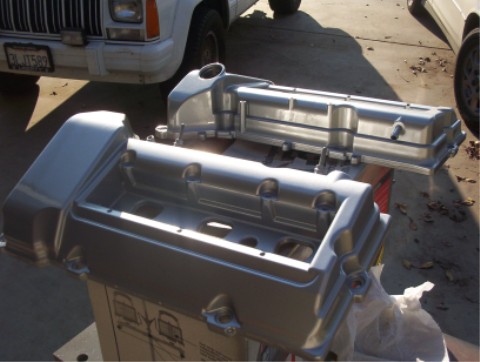
I wanted to have a �matching engine�, so I painted both valve covers metallic silver, and clear coated them. I am not sure how well they�ll hold up under the hood, but I guess we�ll see. I also had to install a 4 cyl throttle cable, as it is almost plug and play. In order to keep the fiero coolant temp gauge, I needed to install the original fiero coolant temp sensor. I had to drill and tap a hole in the water manifold for this. On 96-99 engines, there is a �� NPT plug in the middle of the manifold that can be used(a la aaron88), however, on 93-95 engines (I believe), behind the plug is the EGR passage. Not sure why this changed, but it�s something to be aware of. So, I drilled and tapped the hole originally holding the nipple that leads to the throttle body. The first time, the weak cast aluminum cracked, so I had to grind it down, and start again� but it looks good now:
�More to come as soon as my car has sold (and I have $$$$)�
***EDIT: The years on the EGR plug in the water manifold are just complete guesses... I don't have access to any 96-99 engines, so I assume that's when they changed (they also changed the heads over from the previous 93-95 castings)...
------------------ Northstar 87 GT in progress... Who's got cheats for the learning curve?
[This message has been edited by ryan.hess (edited 06-24-2004).]
IP: Logged
09:46 PM
PFF
System Bot
Jun 22nd, 2004
cptsnoopy Member
Posts: 2587 From: phoenix, AZ, USA Registered: Jul 2003
Ryan.Hess The original V6 dogbone mount has been removed to allow clearance for the N* valve cover and/or coil pack. The battery tray was also removed because it�s ugly, it clears out the space, and I am going to mount the battery in the front.
Did you completely remove the dogbone mount? After examining my setup and discovering the extra coil pack mounts that allow you to move the coil pack 4" to the left, I don't think that much cutting on the dogbone mount is actually necessary.
quote
I also had to install a 4 cyl throttle cable, as it is almost plug and play. In order to keep the fiero coolant temp gauge, I needed to install the original fiero coolant temp sensor.
Thanks for the info. I'll try the 4 cylinder throttle cable. The V6 one works, but I had to modify the bracket slightly to accept it. I installed a T-fitting on the heater line and screwed the Fiero coolant temp sensor in to it. I had to ground the T-fitting externally, but that's easy.
------------------ '87 Fiero GT: Low, Sleek, Fast, and Loud '90 Pontiac 6000 SE AWD: None of the Above
Luck, Fate and Destiny are words used by those who lack the courage to define their own future
IP: Logged
12:30 PM
Rickady88GT Member
Posts: 10657 From: Central CA Registered: Dec 2002
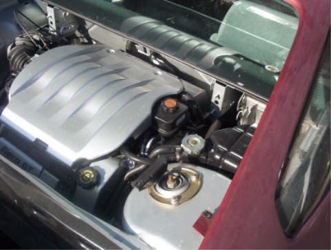
ryan.hess that is a pic after the hole swap and repaint. I had a shop do it for me and cost about $50. Yes they are mag. This is a pic of them in the car. I not only wanted to do it for looks but needed to move the fill boss so I could use the stock deck lid springs. I did not want to add a strut or some other piece in there that would get in my way.
IP: Logged
01:01 PM
ryan.hess Member
Posts: 20784 From: Orlando, FL Registered: Dec 2002
Originally posted by Will: Did you completely remove the dogbone mount? After examining my setup and discovering the extra coil pack mounts that allow you to move the coil pack 4" to the left, I don't think that much cutting on the dogbone mount is actually necessary.
Oh yeah... it's Goooooone! Actually I read up your "move the coilpack over" deal about an hour too late Oh well... Not like I needed it anyways.
quote
Thanks for the info. I'll try the 4 cylinder throttle cable. The V6 one works, but I had to modify the bracket slightly to accept it.
Well you still have to modify the bracket a bit (depending on year N* I suppose?). The cable slides on to the bracket fine, but won't fully seat, so you need to lengthen the slot a bit. Also, I may have to bend the bracket to move it towards the throttle cam, because right now it holds the throttle open about 1/8".
quote
I installed a T-fitting on the heater line and screwed the Fiero coolant temp sensor in to it. I had to ground the T-fitting externally, but that's easy.
I picked up the ECM temp sensor by mistake, but apparently it'll work just as well, and it's got 2 pins instead of one to use (you still have to run a ground wire, but it won't look "out of place" connecting to the fitting I supose). Thanks for the kind words everyone... UPS says they'll be dropping off an electronics "goodie box" today I'm crossing my fingers here, in hopes that my tranny controller will actually work For those of you that don't know, I will be building a box to control the 4t80e.. In effect, it will be quite similar to a 'manual valve body' transmission, but with the option of paddle-shifting later on if need be
IP: Logged
01:18 PM
ryan.hess Member
Posts: 20784 From: Orlando, FL Registered: Dec 2002
ryan.hess that is a pic after the hole swap and repaint. I had a shop do it for me and cost about $50. Yes they are mag. This is a pic of them in the car. I not only wanted to do it for looks but needed to move the fill boss so I could use the stock deck lid springs. I did not want to add a strut or some other piece in there that would get in my way.
Looks good! Hell, it fooled me! I decided against it, but may do that in the future for aesthetics. I will be adding struts, so no biggie there. I think the shape of the two valve covers are different though, and I don't know if there's even a spot to place the oil fill on the "rear" one.
IP: Logged
01:22 PM
Jun 23rd, 2004
Will Member
Posts: 14305 From: Where you least expect me Registered: Jun 2000
I picked up the ECM temp sensor by mistake, but apparently it'll work just as well, and it's got 2 pins instead of one to use (you still have to run a ground wire, but it won't look "out of place" connecting to the fitting I supose). Thanks for the kind words everyone... UPS says they'll be dropping off an electronics "goodie box" today I'm crossing my fingers here, in hopes that my tranny controller will actually work For those of you that don't know, I will be building a box to control the 4t80e.. In effect, it will be quite similar to a 'manual valve body' transmission, but with the option of paddle-shifting later on if need be
I've kinda been thinking about that... The shift solenoids are no problem... just select the right combination... but what are you going to do to control the pressure control solenoid? Going to base the duty cycle and time constant for that from length of time the paddle or button is held? (short paddle or button duration = hard shift, long duration = soft shift?)
Are you going to lock the convertor up solid except to launch and shift, or are you going to treat the TCC lockup like a 5th gear?
------------------ '87 Fiero GT: Low, Sleek, Fast, and Loud '90 Pontiac 6000 SE AWD: None of the Above
Luck, Fate and Destiny are words used by those who lack the courage to define their own future
[This message has been edited by Will (edited 06-23-2004).]
IP: Logged
12:30 PM
ryan.hess Member
Posts: 20784 From: Orlando, FL Registered: Dec 2002
Originally posted by Will: I've kinda been thinking about that... The shift solenoids are no problem... just select the right combination... but what are you going to do to control the pressure control solenoid? Going to base the duty cycle and time constant for that from length of time the paddle or button is held? (short paddle or button duration = hard shift, long duration = soft shift?)
Are you going to lock the convertor up solid except to launch and shift, or are you going to treat the TCC lockup like a 5th gear?
Yeah, the solenoids are no problem. So far, I've been thinking of having a soft/not soft pressure control setup... Basically have a 555 set up for the "minimum pressure", and a pushbutton to disconnect it from the solenoid when I want "max pressure" for full throttle runs. The min pressure would be adjustable via a pot, as you don't want too low of a pressure. I programmed my first microcontroller yesterday... Blinky-light works, so all is go
heh, didn't see your edit there... TCC will be like a 5th gear. I don't really see any benefit to treating it like a clutch (maybe a couple more mpg?) Oh, and I've got a ratings bar! yaaaay!
[This message has been edited by ryan.hess (edited 06-23-2004).]
IP: Logged
02:57 PM
Jun 24th, 2004
aaron88 Member
Posts: 280 From: Ottawa, Canada Registered: Oct 2003
Originally posted by ryan.hess: "In order to keep the fiero coolant temp gauge, I needed to install the original fiero coolant temp sensor. I had to drill and tap a hole in the water manifold for this."
"So, I drilled and tapped the hole originally holding the nipple that leads to the throttle body. The first time, the weak cast aluminum cracked, so I had to grind it down, and start again� but it looks good now:"
I have one concern about this location. It is the best place to bleed the air out of the coolant system when filling it. I tried a number of different ways but came to the conclusion that this was the best place to do it.
Alternately if you added a filler neck and pressure cap (to the upper coolant fitting on the engine block) it would serve the same purpose (also I suppose the pressure cap is also optional, because I didn�t use one).
I don�t know if this is something you have already taken in consideration, but if you have a better idea for filling the system I would be interested in knowing what it is. I�d really like to clean up the ugly filler neck on my coolant system.
Aaron
.
IP: Logged
12:59 PM
ryan.hess Member
Posts: 20784 From: Orlando, FL Registered: Dec 2002
Originally posted by aaron88: I have one concern about this location. It is the best place to bleed the air out of the coolant system when filling it. I tried a number of different ways but came to the conclusion that this was the best place to do it.
Alternately if you added a filler neck and pressure cap (to the upper coolant fitting on the engine block) it would serve the same purpose (also I suppose the pressure cap is also optional, because I didn�t use one).
I don�t know if this is something you have already taken in consideration, but if you have a better idea for filling the system I would be interested in knowing what it is. I�d really like to clean up the ugly filler neck on my coolant system.
Aaron
.
To be honest with you, it's something that hadn't even crossed my mind. I may drill and tap another hole for an NPT plug on top of the manifold for just that purpose? Also, I edited my previous comments on the year ranges for the plug in the water manifold. Those are guesses on my part, I must've forgot to state that on the second time I typed that up
heh... yes, I'm following your thread on fierodrivers.com
-Ryan
[This message has been edited by ryan.hess (edited 06-24-2004).]
IP: Logged
11:01 PM
Jun 25th, 2004
ryan.hess Member
Posts: 20784 From: Orlando, FL Registered: Dec 2002
Hey ryan great idea!! I'm having trouble w/ my 4t80e as we speak. Its got a 95 pcm thats only wired for trans inputs and out puts. needless to say it shifts like s&%t!! Are you willing to sell one of these when you get it figured out? If so how much and when? Also as far as the pressure control goes, you could use the tps or have a throttle switch to give max psi at a predetermined throttle positon. you may also want to have a park neutral input so it doesnt engage hard. That trans is designed to TCC in third and fourth gears not only for fuel mileage but also to keep trans temps down.
IP: Logged
12:52 PM
Jul 5th, 2004
ryan.hess Member
Posts: 20784 From: Orlando, FL Registered: Dec 2002
Alright. Haven't made much progress, still waiting on some parts to come in... But in the meantime, I can show you what I did to my throttle cable bracket.. Basically I had to cut it in 2 places, and move it in towards the cam by about 1/4". (cut/welded areas highlited) Yes it's ugly, it's my first time on a wirefeed
Now, ragerc92, about the potential for purchasing one of my tranny controllers... Entirely possible, but I want to make sure it works first So far, it does everything it should, and I am optimistic. So I'm crossing my fingers. I thought about making the controller 100% automatic via the TPS and/or MAP sensor, but I wanted the fastest way to a driveable car, so I kept it strictly a manual. Of sorts, that is. Maybe it's a semi-auto? If you want a completely custom-built auto controller, PM me, and we can talk further. Keep in mind lead-time would be like a month on a project like this, unless you want the semi-auto that I've got now (no, not MINE, but I can build ya one )...
It would be really, REALLY nice to have this engine up and running this week, but that may be stretching myself thin. I'll keep you guys posted
IP: Logged
06:59 PM
ryan.hess Member
Posts: 20784 From: Orlando, FL Registered: Dec 2002
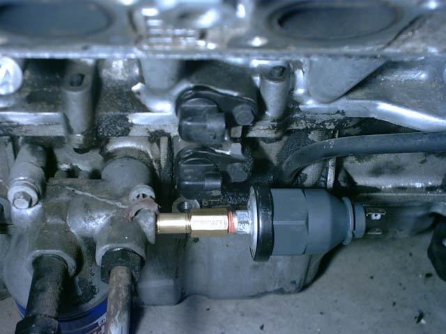
Oh, forgot... I installed the stock 2.8 oil pressure sender. It required a length of 1/4" NPT brass pipe and a coupler. The length between the threads is ~1". I think that makes it about 1.75" or something. btw, this was done so it would clear the crank sensors.
IP: Logged
07:12 PM
Jul 6th, 2004
ato4life Member
Posts: 79 From: Crystal Lake, IL 60012 Registered: Jun 2004
Originally posted by ato4life: sweet ride. when it is all done take it to a trak and post your slip. i was looking at doing this conversion myself. but io dont know any track times.
Might have to. Although the nearest track is 4 hours away I believe (?) [sigh]
quote
Originally posted by Kohburn: wait you made a manual shift controller for the auto? now you need some steering wheel paddles
Well I have provisions for them... When this thing's been on the road for a while, I might just switch over to paddles.
IP: Logged
11:31 AM
Jul 7th, 2004
Will Member
Posts: 14305 From: Where you least expect me Registered: Jun 2000
Oh, forgot... I installed the stock 2.8 oil pressure sender. It required a length of 1/4" NPT brass pipe and a coupler. The length between the threads is ~1". I think that makes it about 1.75" or something. btw, this was done so it would clear the crank sensors.
You can screw an Aurora oil pressure sender right into where the Caddy oil pressure sender goes. The Aurora sender is about an inch longer than the stock Caddy sender, but can drive a gauge in addition to the idiot light and fuel pump relay.
Also... Wiring a stock N* PCM to EVERYTHING EXCEPT the injectors would probably get it to work the automatic pretty well... IE, wire it up so it's getting all the engine inputs (including TPS, MAP, AND 24x/4x/0.5x from the ignition brick). Connect the PCM outputs to the transmission, but don't connect the outputs to the ignition or the injectors. That ought to control the transmission nicely. Of course it will have the stock shift points...
------------------ '87 Fiero GT: Low, Sleek, Fast, and Loud '90 Pontiac 6000 SE AWD: None of the Above
Luck, Fate and Destiny are words used by those who lack the courage to define their own future
IP: Logged
03:20 PM
ryan.hess Member
Posts: 20784 From: Orlando, FL Registered: Dec 2002
Originally posted by Will: You can screw an Aurora oil pressure sender right into where the Caddy oil pressure sender goes. The Aurora sender is about an inch longer than the stock Caddy sender, but can drive a gauge in addition to the idiot light and fuel pump relay.
Also... Wiring a stock N* PCM to EVERYTHING EXCEPT the injectors would probably get it to work the automatic pretty well... IE, wire it up so it's getting all the engine inputs (including TPS, MAP, AND 24x/4x/0.5x from the ignition brick). Connect the PCM outputs to the transmission, but don't connect the outputs to the ignition or the injectors. That ought to control the transmission nicely. Of course it will have the stock shift points...
Good idea. But I already had the 2.8 sender, so I decided to use that instead. Also, I revised the way I connected it... With it sticking straight out like that, it would get in the way of the front mount. So I had to put in a 1/4" NPT 90* elbow in line, so now it is sticking straight down. Today I decided to tackle mounting the battery up front. Pics will be forthcoming when I have finished
IP: Logged
06:19 PM
Jul 8th, 2004
Will Member
Posts: 14305 From: Where you least expect me Registered: Jun 2000
Originally posted by ryan.hess: With it sticking straight out like that, it would get in the way of the front mount. So I had to put in a 1/4" NPT 90* elbow in line, so now it is sticking straight down.
I was wondering about that... Things are pretty tight in that area.
Are you moving the battery to the front just because, or are you making room for a catch tank?
------------------ '87 Fiero GT: Low, Sleek, Fast, and Loud '90 Pontiac 6000 SE AWD: None of the Above
Luck, Fate and Destiny are words used by those who lack the courage to define their own future


 For those of you that don't know, I will be building a box to control the 4t80e.. In effect, it will be quite similar to a 'manual valve body' transmission, but with the option of paddle-shifting later on if need be


 If you want a completely custom-built auto controller, PM me, and we can talk further. Keep in mind lead-time would be like a month on a project like this, unless you want the semi-auto that I've got now (no, not MINE, but I can build ya one