Here is a brain teaser. I just installed a CS Alternator in my 85 GT. It is not charging. I done a little reading and found out that if the volt light is not working the alternator will not charge. BTW. I installed an AUX cluster from an 86 GT in my 85 GT. I tested the bulb itself and it is good. I then checked for bad connections on the lamp house. I found that with the switch on I have 12 volts on one side of the bulb connection using a frame ground. If I try to ground to the other pole of the circuit board it will not ground. I am sure this is not a common ground and has something to do with the charging problem. the problem wire traces back to the brown wire on the aux connector. Do you guys know where this wire should go or what I should do to troubleshoot this problem further?
Thanks
Bill McConkey
IP: Logged
09:29 PM
PFF
System Bot
billmcc1281 Member
Posts: 14 From: Decatur,TN,USA Registered: Mar 2004
The excitement to get the alternator charging comes from the 12 v source, through the bulb and through the brown resistor wire to the alternator. When the alternator starts charging it will have 12 v coming back to the light from the alternator, so it will have 12 v on both sides of the bulb, turning it off.
Test the brown wire with the key on and you should have power in it. If it does not trace it backwards and find where you are loosing it (hint, carefully test C500).
The brown wire could have been a problem (such as coroded and not supplying a good power source to alt) with the old SI alternator and you might not have known it, the SI alternator will "self excite" at about 1800 rpm, the CS will not do this.
IP: Logged
11:48 PM
Mar 18th, 2004
Pyrthian Member
Posts: 29569 From: Detroit, MI Registered: Jul 2002
I did this to my 85 SE last fall. I got the CS alternator & the connector for it. the original alternator has 3 lines to it - 1 being the big red line & 2 on the connector (red & brown) the CS has 4 lines to it - 1 being the big red line & 3 on the connector (red, black & brown) the big red line - thats the same - goes on the stud and, on the connector - cut the old one off, or get an adapter (they do make them - finding them is another story...) and the red goes to red, the brown goes to brown, and the black is left unconnected
The Ogre has a good write up on how to wire up the CS alternator to work in a car that used to have an SI alternator. Check it out at the top of the page in Ogre's cave.
IP: Logged
08:33 AM
billmcc1281 Member
Posts: 14 From: Decatur,TN,USA Registered: Mar 2004
That is exactly how I installed the CS. Red to stud, Red and brown spliced to red and brown on the connector. I think Electrathon has me on the right track. When I installed the aux pod in my 85 GT along with 120 mph cluster I followed a write up to patch in the new pod. I am not sure whether the brown wire that comes off of the volt light in the pod is connected to anything or not I will have to look. If it is not hooked up I have found my problem. Electrathon has another good point. on my SI alternator I would have to rev the engine to get it to start charging. since the SI is self exciting I would not have noticed a problem until now. Anyone know offhand where the brown wire should be patched into if it is not hooked up?
Thanks
IP: Logged
08:48 AM
billmcc1281 Member
Posts: 14 From: Decatur,TN,USA Registered: Mar 2004
Heres an update. I think this is my problem for sure. I found the page I followed to install the 120 mph cluster and aux pod in my 85 GT. http://webserv.absolute-net.com/jgunsett/AuxGageInstal.htm At the bottom of the page I found the pinouts and it says: brown - charge (not used). I follow instructions to a tee and if it said not to use I didn't. So where should I hook this wire up? "The Brown Wire"
Thanks again
IP: Logged
09:43 AM
billmcc1281 Member
Posts: 14 From: Decatur,TN,USA Registered: Mar 2004
The rally gauge cluster has nothing to do with you problem. A brown wire goes to pin �D� on the cluster but is not used by the cluster. It just dead-ends there. The other end of that wire connects to one side of the charge indicator light (C3 pin 5) along with the wire you are looking for that heads toward the alternator. That wire goes through the C500 connector at pin 83, then to the alternator. The diagram shows a diode in that line but I don�t know where that is located. It�s possible that the diode is open or that there is a bad connection at either the C3 or C500 connector.
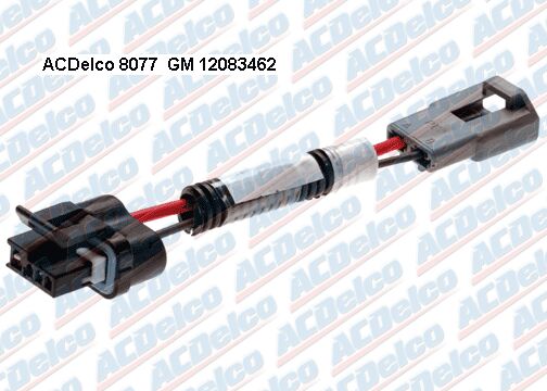
Did you use the GM adapter cable at the alternator end? Pyrthian mentioned earlier that the adapter was hard to find but it is available at GMPartsDirect.com for $11.67 . This is a popular replacement project on lots of GM cars so there are also several aftermarket adapter cables at parts stores.
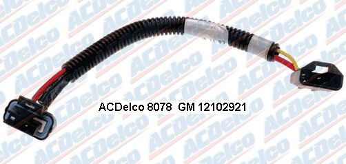
There is also another adapter cable with a built-in resistor for cars without the warning light that may be harder to find. It�s not listed at GMPartsdirect.com.
edit to add image
[This message has been edited by spark1 (edited 03-18-2004).]
IP: Logged
07:02 PM
The Aura Member
Posts: 2290 From: Winnipeg, Manitoba, Canada Registered: Nov 2001
I done a little reading and found out that if the volt light is not working the alternator will not charge. Thanks
Bill McConkey
Ah ha! This could be what's causing my low battery all the time. Seems like that light doesn't work often, if at all, and I've been wondering why my battery is always low.
IP: Logged
07:19 PM
PFF
System Bot
billmcc1281 Member
Posts: 14 From: Decatur,TN,USA Registered: Mar 2004
First off. I fixed the problem. Second a quote from spark1 "The rally gauge cluster has nothing to do with you problem. A brown wire goes to pin �D� on the cluster but is not used by the cluster. It just dead-ends there." On the write up i put a link to earlier, It tells you to do nothing with the dark brown wire that comes from the rally gauge cluster. So I didn't. The brown wire connects directly to one of the terminals on the volts idiot light. the same wire connects to the same place on a standard cluster. So I tapped into it in the cluster harness and then to the rally gauges. as soon as I turned the switch on the volts light lit up. Cranked it up and the light went out and started charging 14 volts. I understand where you are coming from and if I had just added rally gauges and left the 85 mph cluster in I would not have had this problem because of the volts light being also built in to that cluster. But I swapped everything including 120mph cluster which does not have a volts light. A CS alternator is dependant on the volts light functioning and sending an exciter charge to the alternator. A CS must have an exciter charge to operate. before I swapped from an SI I had to rev the engine before it would begin to charge. As I found out from Electrathon an SI will self excite at 1800rpm. Or it will start immediately if you have a functioning volts light. That is the reason I swapped in the first place because of having to rev the engine to start charging. So for all of you with SI's and wonder why you goose it and then it starts charging check out your volts light. Sqoach: this problem only pertains to CS alternators if you have not converted this may or may not be your problem. By the way I followed the instructions here to a tee http://home.sprynet.com/~theogre/tunnel6/makeme/wombatcs/csalt1.htm I used the conduct tite adapter you see there.
IP: Logged
08:42 PM
Electrathon Member
Posts: 5241 From: Gresham, OR USA Registered: Dec 2002
The diagram shows a diode in that line but I don�t know where that is located. It�s possible that the diode is open or that there is a bad connection at either the C3 or C500 connector.
There is also another adapter cable with a built-in resistor for cars without the warning light that may be harder to find. It�s not listed at GMPartsdirect.com.
edit to add image
The diode is only in the harness to the 2.8 vin code 9, not in the 2.5 vin code R
The manual lists the diode location as "In the main harness, below rear bulkhead grommet". No picture is listed.