Hi all, I am having a problem with a hard code 15 on my DOHC swap. The code is for the coolant temp sensor, voltage high. Ive traced all the wiring and it all checks out ok checked the sensor even bought a new one and still I get this code 15. I have even replaced the ECM (9396) and EPROM to check and still keep getting the same hardcode. Any ideas would be appreciated. Thanks
[This message has been edited by Erik (edited 07-12-2003).]
IP: Logged
08:33 PM
PFF
System Bot
Jul 13th, 2003
Erik Member
Posts: 5628 From: Des Moines, Iowa Registered: Jul 2002
still no replies come on guys help! I am wondering if a low coolant sensor would set a hard code 15 if it was disconected. I was looking at the wiring scematics and it shows that on the DOHC Lumina z34 the low coolant sensor is just wired up to a warning light on the dash and isnt part of the ECM input as far as I can tell. I do have a cooling fan constantly running when the car is running and I know thats because I have a hardcode 15. When I wired up the DOHC harness to the Fiero's I left the secondary cooling fan plug hanging as I do not have one on the car.
IP: Logged
12:45 PM
Cliff Pennock Administrator
Posts: 11900 From: Zandvoort, The Netherlands Registered: Jan 99
If the sensor on the Lumina is simply connected to a warning light, then it's a switch - not a thermistor. The Fiero's ECM needs a thermistor as sensor. If it's a switch then it's rest position is open, which will set Code 15 on the ECM.
Removing the sensor will also set Code 15.
If you get code 15 with the Fiero coolant sensor, then if you have a Voltmeter, measure the voltage over the sensor - it should measure 5V.
If you don't measure 5V, you have a bad cable somewhere. If the cables are ok, measure voltage on the ECM between C10 and ground. That should be 5V as well.
[This message has been edited by Cliff Pennock (edited 07-13-2003).]
IP: Logged
05:23 PM
ducattiman Member
Posts: 674 From: TheNetherlands Registered: Mar 2003
CLiff, Thanks for the information. I am using the DOHC original temperature sensor which is a thermistor not a switch. It is a 2 prong sensor. The wires are yellow and black. The yellow wire goes to C connector, pin 16 on the 9396 ECM. That is the input wire. The black is a shared sensor ground (shared with the TPS sensor ground)terminating at the c connecter, pin 10 of the DOHC 9396 ECM. I have checked continuity and voltage on the yellow wire and continuity on the black. The sensor is new. For some reason the yellow is giving 12 volts reading when the ignition is on. I unplugged the C plug on the ECM and then checked to see if the yellow still read voltage and it doesnt so I know its not shorted across to another wire. When I check pin 16 on the ECM without the C plug in and have the igntion on, I get no voltage reading. I am wondering why the ECM is giving 12 volts to the yellow wire. It should give 5 volts reference according to the manual. I have replaced the ECM to check and still the same thing.
[This message has been edited by Erik (edited 07-14-2003).]
IP: Logged
07:29 PM
Jul 15th, 2003
Cliff Pennock Administrator
Posts: 11900 From: Zandvoort, The Netherlands Registered: Jan 99
i believe that we are both experiencing the same problem (although i haven't been able to code the TDC yet). the fan runs the moment i have the engine cranked. it runs if either fan 1 or 2 is hooked up or disconected.
i cut the "green wire" that DKOV mentioned, but that hasn't fixed anything.
Erik, we need to keep in touch as we are both experincing the same problems here.
------------------ hoop Red '86 Z34GT 5 speed Borla Exhaust Eibach's/Poly/Kyb's
IP: Logged
05:19 PM
Jul 16th, 2003
Erik Member
Posts: 5628 From: Des Moines, Iowa Registered: Jul 2002
Ok, I just now realize you are talking about the 16149396 DOHC ECM, not the stock Fiero ECM.
Do you happen to have the pinout for this ECM?
Hi Cliff, Yes I have the pinout but Im not sure how to post it to you. I have tried posting images but they dont seem to work. I will scan them and email them to you if that is alright.
[This message has been edited by Erik (edited 07-16-2003).]
IP: Logged
03:20 AM
Erik Member
Posts: 5628 From: Des Moines, Iowa Registered: Jul 2002
Hi Neverendingproject, Thanks for the link. Regarding the radiator fan constant running whenthemotor is, I had tried the suggestion on the link already. If I disconnected the twin green wires from pin K then the fan would still run. If I disconnected the two green wires from each other then the fan wouldnt turn on no matter if the motor got hot. If I connected one of the green wires back to pin K on the HVAC then once I turn the air on it would run the fan but not otherwise with the air off and the motor hot. Finally if I connected the other green wire to pin K nothing would happen.
IP: Logged
03:29 AM
Erik Member
Posts: 5628 From: Des Moines, Iowa Registered: Jul 2002
i believe that we are both experiencing the same problem (although i haven't been able to code the TDC yet). the fan runs the moment i have the engine cranked. it runs if either fan 1 or 2 is hooked up or disconected.
i cut the "green wire" that DKOV mentioned, but that hasn't fixed anything.
Erik, we need to keep in touch as we are both experincing the same problems here.
Hey Hoop, If I disconnected the twin green wires from pin K then the fan would still run. If I disconnected the two green wires from each other then the fan wouldnt turn on no matter if the motor got hot. If I connected one of the green wires back to pin K on the HVAC then once I turn the air on it would run the fan but not otherwise with the air off and the motor hot. Finally if I connected the other green wire to pin K nothing would happen. I do have my air working, I just ran the high pressure switch wires up front like DKOV mentioned. I really think our problem is a hardcode 15 ( signal voltage high ) which will kick on the radiator fan by default once the motor cranks and runs to protect the motor from overheating. I am getting a high voltage reading (12volts) on Connector C, pin 16 of the ECM which the CTS yellow wire runs to. The manual says it should read 5 volt reference. I have checked the wire for any short to another wire and it checks out. I have also replaced the ECM and chip to test and get the same results. Freakin weird but I guess I will work on it tomorrow and check into it further and let you know. I believe this is causing my motor to go into a reduced power mode, not that it doesnt have alot of power already but I can sense and feel that it is retarding the timing and fuel curve. Do you have to hold the pedal down to start it after running it and letting it set for any lengh of time? When try to start mine after say going into a conveneince store, It doesnt want to start unless I hold the pedal down, then it will varroom and run ok except for the random stall when coming to a stop. I am attributing that to the code 15 and possibly the VSS signal being not fed to the ECM.
[This message has been edited by Erik (edited 07-16-2003).]
[This message has been edited by Erik (edited 07-16-2003).]
IP: Logged
03:39 AM
PFF
System Bot
bHooper Member
Posts: 4157 From: greensboro, nc Registered: May 99
yes, the car can be hard to start after a short drive. i had attributed this to vapor lock, because if i opened the hood, it it started ok.
are you also getting a drain on the battery, causing the car to not have enough juice to start (on occaision)? what about fuel economy (or lack thereof)?
hoop
IP: Logged
07:02 AM
Erik Member
Posts: 5628 From: Des Moines, Iowa Registered: Jul 2002
yes, the car can be hard to start after a short drive. i had attributed this to vapor lock, because if i opened the hood, it it started ok.
are you also getting a drain on the battery, causing the car to not have enough juice to start (on occaision)? what about fuel economy (or lack thereof)?
hoop
I havent noticed mine vaporlocking. I had considered that possiblility when figuring out how to run the fuel lines but then dismissed it when I considered that, the fuelrail is under there( the intake manifold and valley)by design.
I dont seem to have any problem with battery drain, I do have the battery mounted up front. I am using 2 guage cables. I you have yours up front and are using smaller cables then that might be a problem as the resistance would be higher.
I really havent been watching fuel economy because I just got my speedo to work. It does seem to eat more gas. I am thinking thats because it is running rich by default since it has a hardcode 15 in order to protect the motor.
IP: Logged
01:21 PM
DKOV Member
Posts: 1564 From: Portland, OR, USA Registered: Mar 2001
yes, the car can be hard to start after a short drive. i had attributed this to vapor lock, because if i opened the hood, it it started ok.
are you also getting a drain on the battery, causing the car to not have enough juice to start (on occaision)? what about fuel economy (or lack thereof)?
hoop
I had this hard start issue when I first put mine together as well. Turns out, I didn't have the block grounded to the chassis. once the car got hot, it would not restart.
The chassis to ground didn't seem to cure it completely so I ended up running an ground DIRECT to both the motor-to-battery and chassis-to-battery and ZERO problems after that.
As far as the twin green wire pinout from the HVAC console... Keep them tied together but separate the pair from the HVAC. That way the fan comes on when needed but doesn't cause overheating. It shouldn't come on constant, only when the temp kicks it. If it's not comeing on at all and you've got it hooked up as I've outlines, then there is something else wrong and it may be related to you code 15.
As for what that code is pointing to... sounds like you've all gone over just about everything other than a possible downline cross over or false ground somewhere.
Good luck!
DKOV -
IP: Logged
04:38 PM
bHooper Member
Posts: 4157 From: greensboro, nc Registered: May 99
I had this hard start issue when I first put mine together as well. Turns out, I didn't have the block grounded to the chassis. once the car got hot, it would not restart.
The chassis to ground didn't seem to cure it completely so I ended up running an ground DIRECT to both the motor-to-battery and chassis-to-battery and ZERO problems after that.
As far as the twin green wire pinout from the HVAC console... Keep them tied together but separate the pair from the HVAC. That way the fan comes on when needed but doesn't cause overheating. It shouldn't come on constant, only when the temp kicks it. If it's not comeing on at all and you've got it hooked up as I've outlines, then there is something else wrong and it may be related to you code 15.
As for what that code is pointing to... sounds like you've all gone over just about everything other than a possible downline cross over or false ground somewhere.
Good luck!
DKOV -
Hi DKOV, I do have the ground going to the motor directly from the battery and another one going to the chassis. I am using 2 gauge battery wire also. I do believe its something to do with the code 15 after trying everything as posted before. My problem remains to figure out why the ECM is putting out 12v instead of 5v reference to the CTS.
IP: Logged
11:17 PM
Erik Member
Posts: 5628 From: Des Moines, Iowa Registered: Jul 2002
ihave th battery grounded to the crossrail behind the steering rack and to the block.
Erik, it deffinatly sound like we have the same problem. Unfortunatly, I want be able to work on mine for 2 more weeks.
hoop
Hoop, I had to mow the yard today (2 1/2 acres) and then my yappy cousin called and kept me on the phone for several hours (he wants me to help him on his IROC tomorrow) so I didnt get to the motor today. I will look at it further within the next two days and let you know my results. I am really motivated to get this done soon because I know the motor will reward me with more fun as in full power :-)
IP: Logged
11:25 PM
Jul 19th, 2003
bHooper Member
Posts: 4157 From: greensboro, nc Registered: May 99
Erik, Keep me updated on what you learn this week. I'm leaving sunday morn for the bahama's and will be out of touch for a week.
hoop
p.s. i think i have the pully fixed now, tapped it out and used a new pully, all seems well with that.. still need to fix the stall and battery drain.
Hoop, I am working on it and have had some sucess so far. I found out what was causing the code 15 and there are a few more things I need to look at before posting my results. The motor runs better though and idles alot better also. I am currently checking out the VSS signal too as the ECM needs that to run properly also. I'll email you once I am done. Hey, have fun in the Bahamas
Erik
IP: Logged
05:12 PM
bHooper Member
Posts: 4157 From: greensboro, nc Registered: May 99
Maybe you'll get a lot done and be able to email me this week, so I can imediately start annoying the wife with the fiero the moment we get back from Abaco on saturday!
Hi, What caused it was twofold, the temp gauge was sending voltage to the CTS that the ECM was picking up (12v)and is causing a hardcode 15. Once that is fixed via running a separate dedicated CTS to the temp gauge then an intermittant code 15 would show as a result of a constant 5 volt reference sent out by the ECM. The ECM wants to see a 2.5 volt reference split between two CTS's ( the one on the intake manifold and the one on the front head. Running just the CTS on the intake manifold reference signal to the ECM causes too much (5v) so it must be connected with the other CTS in tandem on the front head to get the 2.5v reference signal that the ECM wants to see.
------------------
[This message has been edited by Erik (edited 08-20-2003).]
Thanks that helps alot. I'm having the same poblem you were-I wired mine just like you did because that's the way DOHCFiero.com said to. Now that we know it's wrong we can fix it for good on the site once we get some more testing in. The wiring diagrams I have show the two wire CTS going straight to the ECM and the single wire either going to a light or a gauge depending on what model you have. Has nothing to do with the ECM. Have you checked your coolant temps with a scanner? I would be interested to know what they look like.
------------------ Alan Frazier '86 GT-'92 3.4 TDC under construction '84 2m4 daily driver '88 Silver coupe, auto For Sale
IP: Logged
06:07 AM
Nov 24th, 2003
qwikgta Member
Posts: 4671 From: Virginia Beach, VA Registered: Jan 2001
Hey guys, i was going over all the old posts about the harness for the 3.4 DOHC. I have my harness now, and will start to put the Fiero one together with the 3.4 I was reading this post, i have printed out all the stuff off DOHCfiero site, and was going to use that info. Has this been added to the site. If not, what do i need to do, so that i dont have this prob. thanks
Rob
------------------ 88 TTop coupe, soon to be fitted with a DOHC 3.4/5spd (on hold again for Uncle Sam)
IP: Logged
09:54 PM
Nov 25th, 2003
Erik Member
Posts: 5628 From: Des Moines, Iowa Registered: Jul 2002
Thanks that helps alot. I'm having the same poblem you were-I wired mine just like you did because that's the way DOHCFiero.com said to. Now that we know it's wrong we can fix it for good on the site once we get some more testing in. The wiring diagrams I have show the two wire CTS going straight to the ECM and the single wire either going to a light or a gauge depending on what model you have. Has nothing to do with the ECM. Have you checked your coolant temps with a scanner? I would be interested to know what they look like.
Sorry Neverendingproject that I never got back to you before now, never noticed your post till now. That being said, I am running about 180 degrees warmed up with a low temp thermo.
[This message has been edited by Erik (edited 11-25-2003).]
IP: Logged
04:44 AM
Erik Member
Posts: 5628 From: Des Moines, Iowa Registered: Jul 2002
Hey guys, i was going over all the old posts about the harness for the 3.4 DOHC. I have my harness now, and will start to put the Fiero one together with the 3.4 I was reading this post, i have printed out all the stuff off DOHCfiero site, and was going to use that info. Has this been added to the site. If not, what do i need to do, so that i dont have this prob. thanks
Rob
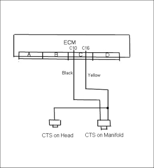
Here is a simple diagram of what I did to fix the hardcode 15 The ECM wants to see a 2.5 volt reference split between two CTS's ( the one on the intake manifold and the one on the front head. Running just the CTS on the intake manifold causes the reference signal to the ECM to be 5v which is too much and will set an intermittant code 15, so it must be connected with the other CTS in tandem on the front head to split the voltage by half which will send the proper 2.5v reference signal that the ECM wants to see.
[This message has been edited by Erik (edited 11-25-2003).]
IP: Logged
05:00 AM
DreXteR Member
Posts: 1763 From: Orlando, FL Registered: Aug 2000
Hi guys. A few time ago I found some flaws in the wiring. The changes have been done in DOHCFiero site already. One of them is the cause of the Code 15. I mistakely route the CTS signal wire to the gauge. This was feeding additional volts to the CTS reading in the ecm makeing the hard code 15.
So far I have once again a hard code 15. But this time I have 7V. I cut the wire in the ecm to isolate any possible outsurce contact but still getting 7V from there.
If anyone have a lead or solution will be helpful.
Thanx DreX
IP: Logged
12:20 PM
Feb 15th, 2004
qwikgta Member
Posts: 4671 From: Virginia Beach, VA Registered: Jan 2001
I am almost finished with the harness, and im going over notes to make sure that i have things covered.... When i got to this note/diagram i had printed out, it confused me because i had an issue with this before on the DOHC web site.... that question went unanswered so here i am.
I copied the diagram and see how it is wiered up, but my question is on the DOHC website it still has the wire set up from the CTS on the head (guage input) going to both C2/D3 on the C500.
The CTS on the manifold (temp sensor to ECM) going to the ECM (yellow C16, black C10)
If i take the wire from the CTS (guage input) (C500 C2/D3) and connect it to the Yellow (C16, ECM input) what will send the signal to the guage/light. How will the Temp light/Guage in the dash get a signal
OR.... do i run an ADDITIONAL line from the CTS (head) to the CTS (manifold) (yellow wire)... will splitting the signal change what it is sending??
Thanks
Rob
[This message has been edited by qwikgta (edited 02-15-2004).]
Those should stay completely seperate. Let the one on the head feed the gauge and leave the two wire on the intake for the ECM. That's a typo on the site, I emailed them but they never changed it. If you want a coolant temp light you can always connect it to the second fan output from the ecm and have a custom chip made with a slightly higher temp. for that output.
------------------ Alan Frazier '86 GT-'92 3.4 TDC 5 speed(for sale) '84 2m4 daily driver '88 Silver coupe, auto For Sale
neverendingproject I thought that was what was causing the hardcode 15? I was told to connect the two sensors together and then run a third sensor for the gauge but Im not sure how much I like that idea. Can someone who has thier car running WITHOUT getting a code 15 give alittle imput here?
IP: Logged
08:09 AM
PFF
System Bot
joshua riedl Member
Posts: 1426 From: watertown wi USA Registered: Jan 2004
the thing is you guys once again made it impossibly difficult to figure this out and scared everyone off who wants to do this swap. all these wires are already wired up and you shouldn't have to touch them. the only thing you need to do is hook up the gauge to the sensor by the transmission. the fan has power as soon as you turn on the ignition so the computer gives the ground so find fan conrol on dohcfiero.com and hook it up.
IP: Logged
08:30 AM
qwikgta Member
Posts: 4671 From: Virginia Beach, VA Registered: Jan 2001
Joshua, once again, you shoot off your mouth without reading.... i think you want to help, and i am glad you have an engine in your car that works, but you have to read more than the last post before you start typing.... this is how we share information, we help each other.
This is at least the 3rd post you have replyed to that offers no help, just your input on how much of an A$$ we all are for not getting it right.
Only post a reply that will help the situation, stop shooting from the hip.
If you would read the entire thread, you will see all the other "hardcode 15" information, i don't want to retype it here.
What i am asking is that according to the diagram above, moving the CTS guage wire over to the yellow CTS (ECM) input wire will stop the code. Erik says it stopped his problem. What im asking is after you do that, what sends the signal to the guage.
Thats all, nothing about a Fan, and if someone is scared off because im asking questions then they really dont want to do the swap.
qwikgta, do you need the real GM diagrams for the DOHC? Those sensors are seperate. Nowhere in any GM diagram does it show them being wired together. The gauge gets one and the ECM gets a different one.
Code 15 is coolant sensor low temperature. It's disconnected (sensor bad, wire broke) or the ECM is bad. Cold it's a high resistance, hot it's a low resistance.
neverendingproject I thought that was what was causing the hardcode 15? I was told to connect the two sensors together and then run a third sensor for the gauge but Im not sure how much I like that idea. Can someone who has thier car running WITHOUT getting a code 15 give alittle imput here?
You're in luck, my car runs great with no more code 15 now that I followed the diagrams instead of the website.
------------------ Alan Frazier '86 GT-'92 3.4 TDC 5 speed(for sale) '84 2m4 daily driver '88 Silver coupe, auto For Sale
IP: Logged
03:15 PM
joshua riedl Member
Posts: 1426 From: watertown wi USA Registered: Jan 2004
you know qwikgta, you are right. i am tires of shooting off at the mouth but unfortunately that's the only way to get you to pay attention. i did read the whole thread and it pains me to see you guys doing these things and then when i come up with the right answer you still listen to everyone who can't get their cars to run right. on top of that TK writes the same thing i just said and i bet you listen to him. when you start with a wire with 5v and split it into two, how many volts do you now have at each wire? that's right 5v. not 2.5. i'm not an electrician but i can figure out that much. now where the 7v is comming from is anybody's guess. maybe some wires got rubbed through by the altenator or something else that rotates and is shorting across. basically their is no help for you because you shouldn't have messed with it in the first place so i can't guess and tell you to unhook a wire or something all i can tell you is you should have left it. this is by far the cheapest swap possible. all you really need to buy is a wiring diagram and fab a dog bone. then of course you guys want to cry about diagrams being too expensive when your car would be running right now if you would have just bought it. i even take the time to look in my haynes manual and dohcfiero before i post answers so i know when i tell you to look somewhere i know it's there. but you are too lazy to look, you just sit on pennocks and hope for somebody else to do the work for you. on my car i cut the harness completely in half right behind the speaker wires because somebody like you felt like cutting into everything that should have been left alone. did i sit on pennocks and ask everyone what this green wire in this big bundle of wires is for? no i didn't, i actually grabbed a multimeter and did some work. you might want to try it. so now i am done trying to help you. good luck though. i mean that, it's a fun car to drive.
joshua, quit being an ass. Some of us need to learn somewhere. I'm so sorry we bother you with our petty questions but what else are we to do if we don't know everything as you do.
IP: Logged
03:29 PM
sspeedstreet Member
Posts: 2306 From: Santa Maria, CA Registered: Dec 2002
you know qwikgta, you are right. i am tires of shooting off at the mouth but unfortunately that's the only way to get you to pay attention. i did read the whole thread and it pains me to see you guys doing these things and then when i come up with the right answer you still listen to everyone who can't get their cars to run right. on top of that TK writes the same thing i just said and i bet you listen to him. when you start with a wire with 5v and split it into two, how many volts do you now have at each wire? that's right 5v. not 2.5. i'm not an electrician but i can figure out that much. now where the 7v is comming from is anybody's guess. maybe some wires got rubbed through by the altenator or something else that rotates and is shorting across. basically their is no help for you because you shouldn't have messed with it in the first place so i can't guess and tell you to unhook a wire or something all i can tell you is you should have left it. this is by far the cheapest swap possible. all you really need to buy is a wiring diagram and fab a dog bone. then of course you guys want to cry about diagrams being too expensive when your car would be running right now if you would have just bought it. i even take the time to look in my haynes manual and dohcfiero before i post answers so i know when i tell you to look somewhere i know it's there. but you are too lazy to look, you just sit on pennocks and hope for somebody else to do the work for you. on my car i cut the harness completely in half right behind the speaker wires because somebody like you felt like cutting into everything that should have been left alone. did i sit on pennocks and ask everyone what this green wire in this big bundle of wires is for? no i didn't, i actually grabbed a multimeter and did some work. you might want to try it. so now i am done trying to help you. good luck though. i mean that, it's a fun car to drive.
Only thing that puts me off on doing this swap is wading through crap like this hoping there's some useful info in it. Chill out, man. Some of us are trying to enjoy this forum.
------------------ 1988 GT, 5-speed, white, beechwood leather, trying to get my 3.4 DOHC put together.
IP: Logged
05:09 PM
qwikgta Member
Posts: 4671 From: Virginia Beach, VA Registered: Jan 2001
Im glad im not the only one who is sick of his crap... i printed every page of the DOHC site, got books for every part of the swap. read every post on pennocks and printed out a book of infomation. I purchased two harness's so i could cover every angle, then went out and got another 88 harness so i could leave my original one intact.
I have traced every wire, made every cut after checking it twice, I ref the DOHC instructions, my Haynes and the GM tech manual before each wire was cut and connected.
ONLY after i found two or more sources who conflict with each other (haynes vs. GM, GM vs pennocks, Haynes vs Pennocks etc..) did i post a question. Some of my questions were stupid, and after you or someone else gave me the answer i looked over the pages and realized it was right there, i slowly started to learn how to read the diagrams....
I have learned more in the last few weeks about MAF, MAP, IAC, CTS, EGR........ than i ever knew before. HELL, i can go to the junk yard now, look into a GM car and point out the sensors, tell you where the wires go, and even tell whats missing when someone cut something off...
Its all learning..... Im glad your car works, and yes... i have asked a lot of questions, but i also keep reading that people are having problems. If i have a problem i post what i did to fix it. The thing that gets me is trying to ignore all the PM's and mail from people who want to give me "there best guess".... i have a ton of mail on people telling me what they "think" will work.
With all the DOHC conversions here, you would think that there is one way of doing it.... Oh, by the way smart a$$, I contacted WCF, and was told that they dont have a diagram for me, using the 96 motor, 91 ecm and Isuzu trans..... I asked them all my questions and they said they would "get back to me" with the answers to help, that was over two weeks ago, nothing.
even your last post was crap... i have not made a cut to the wires i was asking about, but again, you assume i already have done it, and you spare no time telling me what an A$$ i am for doing it.... again, i didn't do it, im asking if this is correct..... i ask, BECAUSE IT DOES NOT MAKE SENCE, you see.... im with you on this, but you are so quick to jump my A$$ you dont even see it.
I am not an electrician, so when i see a wire that has 5V and you cut it, sending the signal to two places, it makes me think that 2.5 goes one way, 2.5 the other. It makes sence to me, so no i dont get what you are saying.
did you even look at the diagram Erik posted... that is what im asking about. See, i have my harness wired up like you and TK say, the reason i posted this is to make sure that i dont find this Code 15 and then have to run the wires like Erik did.
SO, if you wish to post agian, understand that im asking for help, not your crap.
Ok so now after skimming the last few posts I see this turned into another pissing match. Neverendingproject can you please tell me how you did yours? Im not sure I have the same diagrams you have and would like to get this correct the first time.