okay, everything is wired up as per the instructions i got from the website. the orange stage limit wire is taped, but there are 2 other black wires that seem to not have a home. problem is that it won't fire. it has a good ground, and it's getting +12V. the confirmation light doesn't even come on when i flip on the ign switch. anyone have any ideas? i'm lost, and the low RPM misfire is getting worse with the stock ignition...
i'm using an MSD blaster coil, i dno't know if that makes a difference.
do i need a universal trigger adapter?
IP: Logged
12:09 AM
PFF
System Bot
filthyscarecrow Member
Posts: 637 From: minneapolis, MN USA Registered: Jul 2000
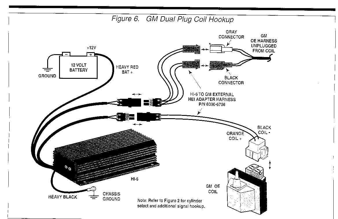
Here's the diagram I used to hook mine up. I didn't need to splice anything as I ordered the GM harness adapter. Hope this helps. You only use one side of the coil to plug in.
------------------
[This message has been edited by avengador1 (edited 05-28-2002).]
IP: Logged
09:22 PM
filthyscarecrow Member
Posts: 637 From: minneapolis, MN USA Registered: Jul 2000
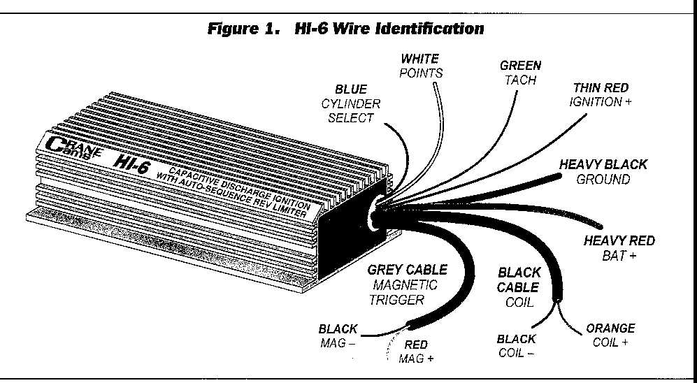
yeah, it is the HI6S. i spliced the red into the pink wire on the grey plug (+12V, verified with voltmeter), cylinder select is connected to ground, coil - terminal connected to the white coil - wire on the grey plug as well. white trigger wire is attached to both the tach and module terminals, brown retard input is attached to switched +12V, and stage limit wire is taped.
did i forget something, or do something wrong? like i said, the status light does not come on, and crane's tech line is not working.
IP: Logged
11:34 PM
May 29th, 2002
avengador1 Member
Posts: 35468 From: Orlando, Florida Registered: Oct 2001
I'll post another wiring diagram I have tonight when I get home from work. It shows all the wires, colors, and where they go. I also remembered that the tach signal is the one from the tach filter plug(where the tach filter used to plug in, you have to remove it) that looks like a "T", use the top part of the "T"(horizontal connection) to plug in. The Green wire plugs into there. I assume you have a V6. If you do, the Blue wire gets grounded. It is not a ground for the unit, you need to have the thick black wire grounded for ground. You said you have two black wires left over, you shouldn't have any black wires left over. If your status LED is not lighting up when you turn the ignition on, you have to make sure that you are getting at least 9.5 volts to the unit, you also have to make sure that it is properly grounded. I would suggest that you get the Crane LX-91 coil as it is made for this ignition system. This also simplifies the installation hook-up. The Orange and Black pair of wires hook up to the coil. The Red and White pair hook up to the original plugs that went to the coil. The Orange wire is hooked up to the coils + side and the matching black goes to the - side of the coil(they only should be plugged to one side of the coil as both positions are not used). The Red wire is hooked up to the switched +12 volt of the GM OE harness unplugged from the coil and is connected to BOTH the Gray and Black OE connectors. The same goes for the White wire. You would have been better off buying the Adapter harness than trying to splice all of these things together. This also would have allowed you to go back to your original ignition a lot easier. Hope this helps, I'll check back later to see how you are doing. It might just be that you don't have your unit grounded properly and you need to use BOTH the Grey and Black OE connector wires.
[This message has been edited by avengador1 (edited 05-29-2002).]
IP: Logged
12:10 PM
Shaun41178 Member
Posts: 1285 From: Whiney McWhinersons Moms Coochie Registered: Jan 99
I dont' know what this msd coil looks like. Does it look like the factory one? I would recommend getting the PS-91 coil. Its a direct replacement for the stock gm coil.
I would also get the GM adapter harness. Its like $30 bucks or so
You shouldn't have any black wires left over. I only remember one being on my box.
black wire goes to ground. The red wire goes to the ignition. So when the key is on the box is on. I have the diagram for the adapter harness which pretty much makes it plug and play.
Blue wire goes to ground if you have a 6 cylinder. if 4 connect to 12 volt supply or same as from ignition switch(red wire)
Orange wire I taped up. did not use
if you get the quick harness it is much easier.
You probably dont' have power cause you dont' have the box grounded correctly. Make sure that when the ignition is on that the box is getting power not just the wire to it.
I need more info to help further.
IP: Logged
05:22 PM
avengador1 Member
Posts: 35468 From: Orlando, Florida Registered: Oct 2001
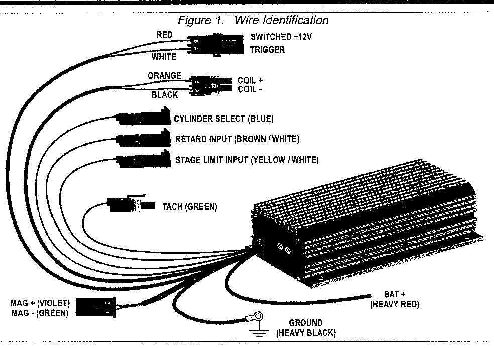
okay, the MSD coil is a factory replacement for the V-6, looks exactly the same as the original. the instructions i have are a bit different than yours avangador, the yellow is supposedly the coil-, the white the trigger, the brown the retard input (the HI6S has built in retard function), the orange is the stage rev limit, the blue is cylinder select, the heavy black is ground, then there are 2 16awg black wires extra, and the red is ignition +12V. the red wire going into the box has 11.6 volts to it with the key on, and the heavy black is well grounded. the other two black are taped up. i didn't want to put power or ground to them because i dno't know what they're for, and they're not in the instructions that i have...
i'm gonna look up the model numbers tomorrow. maybe that'll help. i really appreciate the help guys...
IP: Logged
11:25 PM
May 30th, 2002
filthyscarecrow Member
Posts: 637 From: minneapolis, MN USA Registered: Jul 2000
Try looking up your exact model at www.cranecams.com they should have the exact wiring diagram you need, or post your exact model and I will do a search for you.
IP: Logged
07:27 PM
PFF
System Bot
88CoupeV6 Member
Posts: 1578 From: New Bedford MA Registered: May 2001
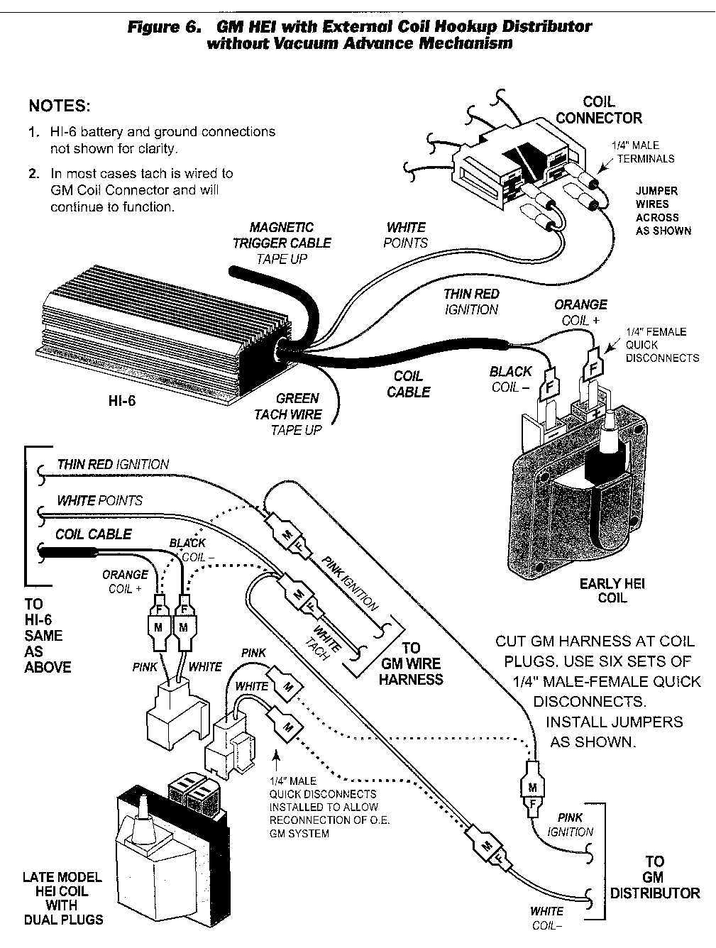
OK, after rereading your post I figured out you have the HI-6S. Here is the diagram for that model. One black wire goes to the coil the other is for a magnetic trigger. It looks like there is a thin red that is supposed to wired to the ignition + and they recommend using their coil (PS91 or LX91). Hope this helps. I also found this diagram which I think will be helpfull, especially the lower half of the picture.
[This message has been edited by avengador1 (edited 05-30-2002).]
IP: Logged
08:57 PM
May 31st, 2002
avengador1 Member
Posts: 35468 From: Orlando, Florida Registered: Oct 2001


 I also found this diagram which I think will be helpfull, especially the lower half of the picture.