My 4.9 wiring thread
Topic started by: Mickey_Moose, Date: 02-02-2009 02:32 PM
Original thread: https://www.fiero.nl/forum/Forum2/HTML/098096.html
|
|||||||||||||||||||||||||||||||||||||
|
See Rockcrawls site for info on the engines mounts: http://www.fieroaddiction.com/caddy49c.html Note: please PM stickpony for ECM programming (VATS/etc) [/shameless plug] Lately I have been asked a lot of questions, so here is all the info that I use in 1 location: These notes apply to a 86 coupe using: a 91 Deville and using the 4.9 ECM's cruise control and speedo outputs with the passkey enabled as well as a standard tranny and the Fiero's charcoal canistor (the 4.9 stock canistor has purge controls) General info: DO NOT USE ANY TYPE OF CRIMP ON WIRE SPLICE (ie: butt connectors) - always solder and heat shrink your connectors (use weather proof heat shrink in the engine bay to help keep water out). Pull apart the harness (remove all the tape), run the wires as you see fit, make the connections (ie: tps sensor wiring goes to the tps inputs on the ECM). The real wiring comes where you have to merge it into the Fiero harness. Method: - remove the C500 from the original engine, mark where all the wires attach to the motor, they will more than likely go to the same location on the 4.9 (ie: tach wire goes to tach output on coil, etc). - I remove the bulkhead pass through from the stock harness using a heat gun and pulling it apart (it is full of hot melt glue). Once clean I install this back into the car. - remove the C203 connector from the engine harness, cutting any wires as long as I can - do NOT cut the wires that feed the ALDL plug and fuel relay (well you can, but you will just have to reattach them again). - I cut the firewall bulkhead on the 4.9 harness off. - remove all tape and loom - connect up each sensor and lay the wiring on the motor how I like to route them. - bundle each sensor group of wire together and mark them (ie: tape all the tps sensor wires together and label tps). - temp tape the bundles together as they will lay on the motor and feed the ends through the Fiero's firewall (through the bulkhead connector). - remove the drivers seat and sit on the floor - take each separate group of wires and start splicing them to the correct ECM plug location (cut to length or lengthen as needed). This part you will need is the diagrams that shows the 3 Caddy plug pinouts (2 pages). Once you identified the pins you simply solder the wires together (the wires colors will be the same color so this makes it simple to match up the correct wire). I usually work with the engine/ECM harness first (connect ECM power/grounds), then the C203 and then the C500. I usually then run the wires for the cruise. Once the engine is running fine, then I will tape the harness and add any wire looms. I add a couple extra short wires into the bulkhead passthrough and then fill it with hot melt glue (the extra wires are in case something get added later (car starter, alarm, etc that way you don't have to drill excess holes). Picture of a semi complete wiring harness (missing: cruise connections, injector harness (on motor) and C500 connector): 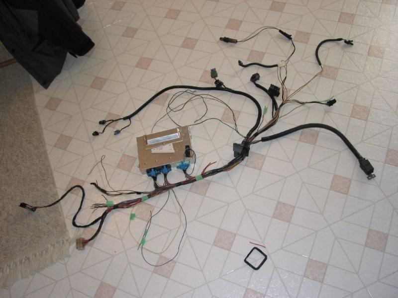 Info: The Pass-Key module (if not programmed out): Is just a black box it feeds the ECM at pin F10 - you are better off to build the circuit on Rockcrawls site - with the original module you will still have to figure out what resistor value is needed. It can be done as I have done it, but there is no advantage over using the original module (plus it is a lot bigger in size vs the 555 timer circuit). My car currently runs the 555 timer circuit. Word file with passkey info and circuit diagram (Note: the 4.9 uses the Passkey 1 system): 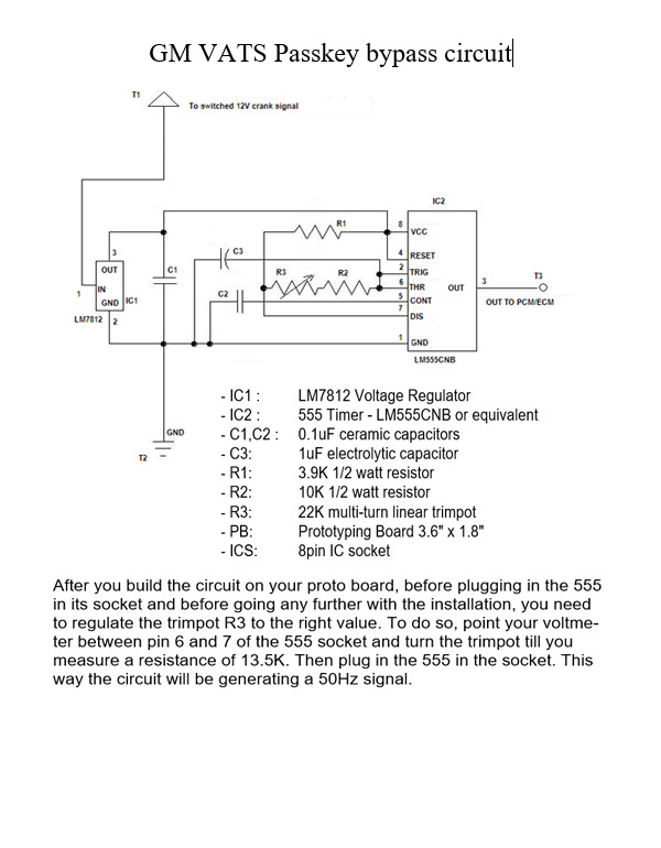 Power steering ECM input Has to be connected to +12v Standard transaxle: You must connect ECM C10 & F7 to ground, the other transmission pins can be removed. Oil pressure switch: Use the one for a 2.8 88 Fiero and wires as: PNK/BLK - C203 positive feed for fuel pump relay (hot at all times). TAN - C203 oil gage feed TAN/WHT (or GRY) - C203 positive side of fuel pump, to the COM terminal of the relay also ECM E/13 BLK - ground Temp sender (also see NOTE): Located in the thermostat housing (from a 2 wire unit to a 3 wire): use these parts numbers for the correct sender: GM 10096181 AC-Delco 213-815 Borg Warner WT3024 CarQuest TX66 Filko CS-43 GP Sorensen 38-5124 Niehoff DR134TA Napa/Echlin ECHTS4020 Connector comes off a 92 Cavalier or the 3800SC - but most 80-90's GM tps sensor plug will work. pin "A" BLK wire on the switch goes to ecm "E11" pin "B" YEL wire on the switch goes to ecm "E16" pin "C" GRN wire on the switch goes to C500 gage connection NOTE: Some 4.9's have a temp switch in the side of the head: 1) if you car does NOT have a temp gage and just an idiot light you can leave the stock 4.9 sensor in the thermostat housing - wire this to the ECM, the one in the head gets wired to the idiot temp light on the dash. 2) if you have a temp gage in your car you change out the sensor to the above info and wire, the head temp switch can be thrown out (or used for an additional light that you have added to the dash). Modify the tach: many threads here on how to do this. Speedo: If you are using the stock Fiero transmission and stock speedo you can simply T off the VSS wires coming from the sender, feed both the ECM and the speedo from teh VSS sender. build the speedo clamp circuit as follows (only needed if feeding the speedo from the ECM): 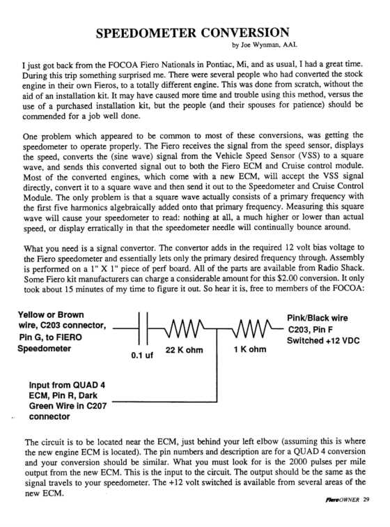 Connects as: Note: the diagram shows the purple wire in the C203 going to ground, you can leave this out as this wire already connects to ground through the speedo. I normally remove this wire from the ECM side of the C203. The C203 connector opens like a clam shell so it is easy to add/remove wires and pins to this plug neatly. 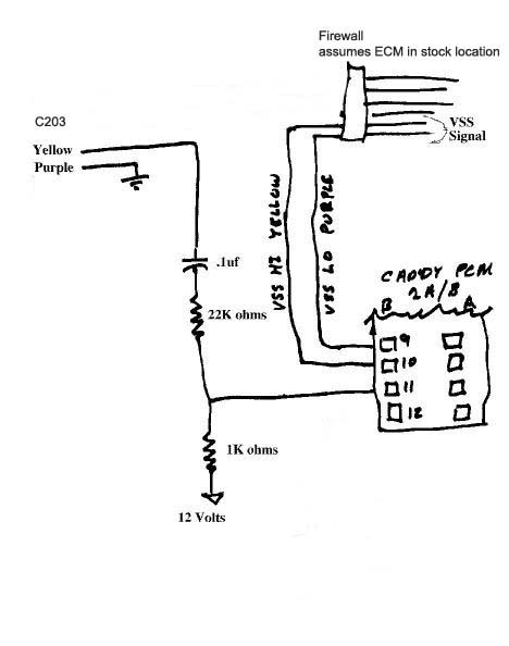
***ADDED INFO***
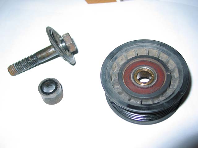
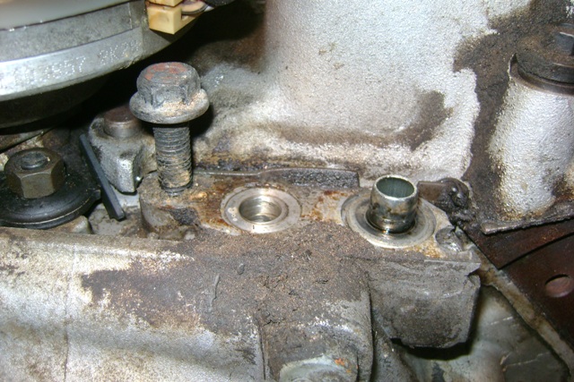
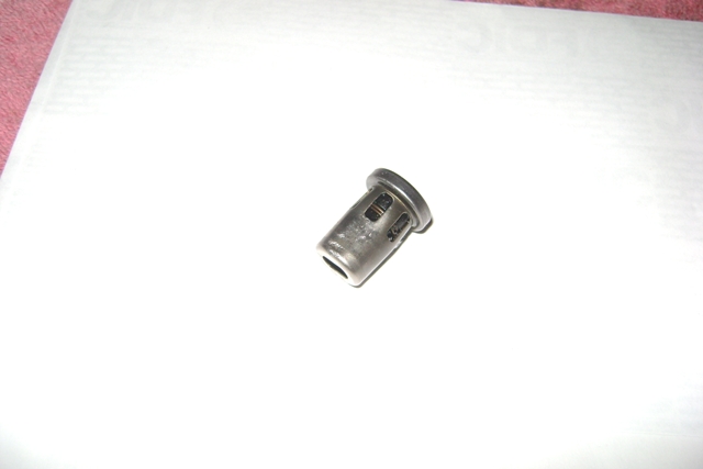
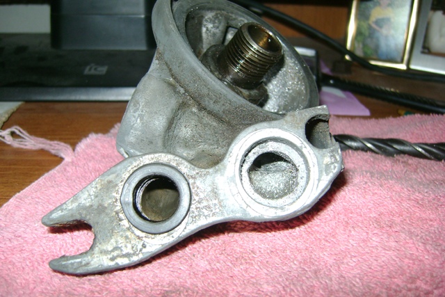
Throttle cable: the 88 Fiero 2.5l throttle cable (no cruise) is a direct bolt in - these are no longer available new, so you will have to find a used one or crimp an end to your original cable that will fit the 4.9 throttle body. Tensioner: System I use (I am told it is similar to Ed Parks): https://www.fiero.nl/forum/A...050818-2-052483.html Idler pulley: Fits a 90 Chevy Astro Van 4.3 V6 NO FACTORY A/C
Belt size: This would all depend on your setup. I have usually used 79.5" or 80.0" belts - this ASSUMES, a/c compressor, idler pulley below the alternator and suggested idler near the water pump and Camaro tensioner are used. Fuel Pump: The stock Fiero 2.8l (V6) fuel pump works fine, some people have upgraded to using the Corvette or Grand National ones. Oil cooler delete proceedure , should you wish to go this route: - from this thread: https://www.fiero.nl/forum/F.../HTML/104610.html#p1
Auto transaxle wiring: I am just providing this info, I have not personally done one: 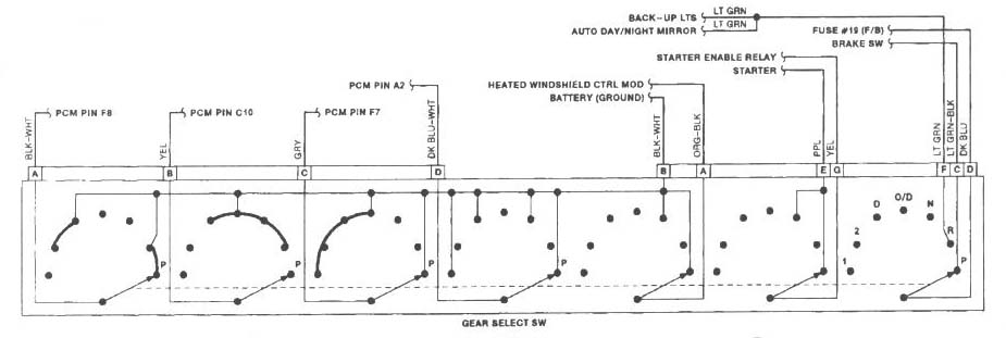 With regards to wiring a 94 transaxle up to a 91 ECM ( https://www.fiero.nl/forum/A...070315-2-077614.html ):
AC info: A/C delete pulley (in case you not using a/c, but still want the ertra belt wrap on the water pump): http://www.am-autoparts.com...urce=YahooShoppingSF AC wiring: 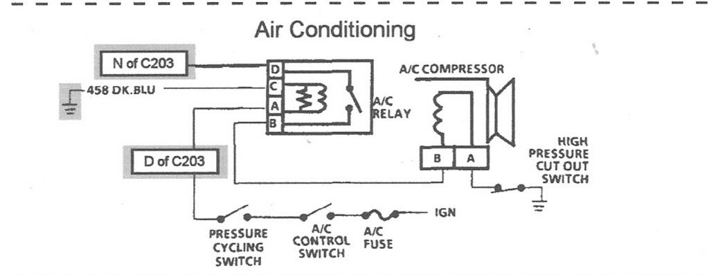
Alternator info: 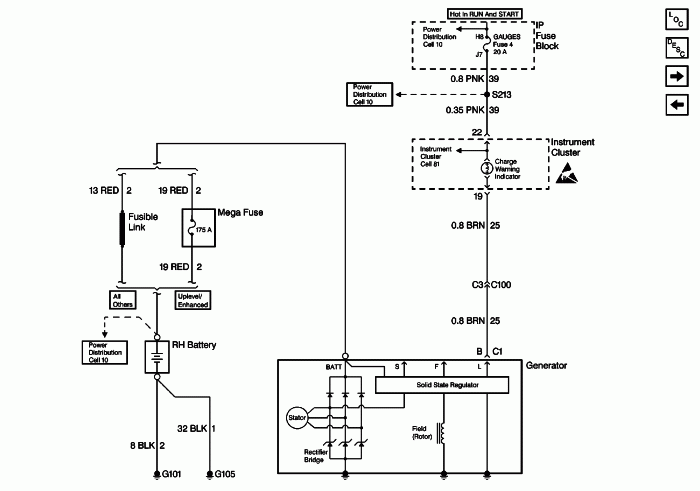 Also see: https://www.fiero.nl/forum/A...090219-2-081509.html http://www.highampalternato...om/cs130_sbpage3.htm http://www.autorewire.com/t.../Delco10SInandd.html Fiero cruise bracket: If you are going to use the stock Fiero cruise system with the 4.9, you can use the 4.9's cruise cable, but you will need to modifiy the bracket that holds the vacuum solenoid. It needs to be made longer. Here is a picture of mine, the area indicated in blue was added to give the length needed. 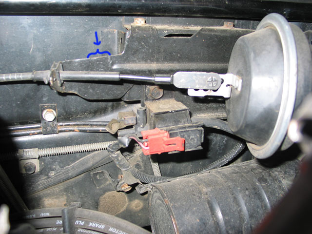 Also, this was brought to my attention, so something to keep in mind (for some reason it does not apply to my car):
...Verified...
Fuel lines: From a V6 car, you will need (with thanks to Fieroseverywhere for the part numbers and links): 14mm o-ring to -6AN - you need 3 of these http://store.summitracing.c...700+115&autoview=sku 16mm o-ring to -6AN - you need one of these http://store.summitracing.c...700+115&autoview=sku Plus hose... Vacuum hoses: 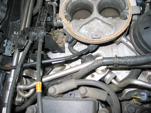 1 - capped off, this would go to the vacuum port on the automatic transmission 2 - regulator on fuel rail 3 - MAP sensor 4 - brake booster (attaches to the filter that is on the firewall) 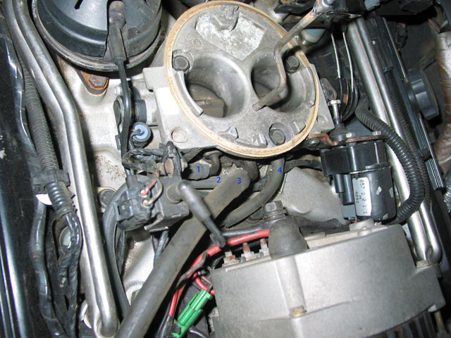 1 - goes to the charcoal canister (small port) marked "control vac" - also has a T inline to feed the cruise vac can 2 - goes to the larger port on the charcoal canister. these hoses connect to the steel lines that are running along the trunk. NOTE: I am running the Fiero's canister, the Caddy one will hook up the same, you just have to add the wiring to the ECM for it. 3 - PVC Valve - I rotated the tube so it points towards the rear of the car 4 - EGR solenoid Coolant hoses:  Here is the small hose that is coming off the thermostat housing, feed to the heater core. On my car there is a metal tube that runs along the frame in a channel (the red clip is holding the metal tube to the metal body. The people that do not have this hose here have modified the thermostat housing so that this hose runs along the big one off the thermostat housing - REMEMBER my car was a 4 cyl, so you may not have the metal tube.  This picture shows the metal tube a bit better - it is wrapped in a black foam (I assume is for heat retention). 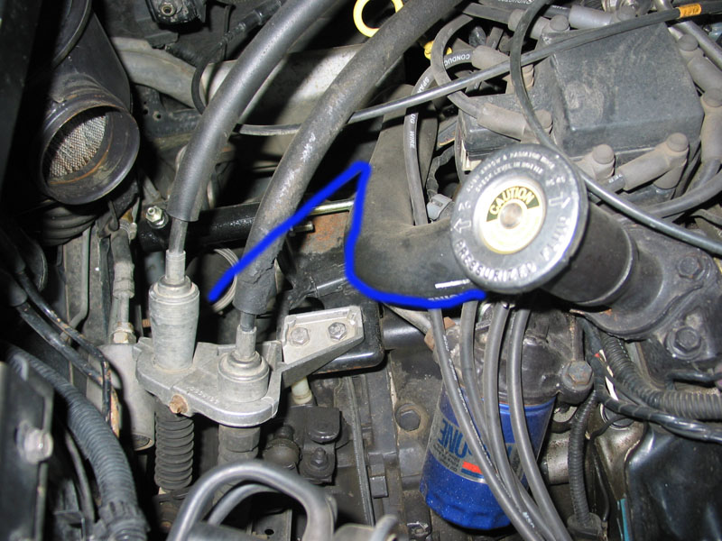 Shows my thermostat housing (modified by welding the top half of the 4 cylinder on to the base of the original 4.9 housing). This hose feeds down to the rad tube that runs under the drivers side of the car (the stock 4 cylinder hose works just right here with a small extension near the bottom to reach the tube. The blue line sort of shows the path. The tube that runs under the passenger side of the car feeds the larger port on the water pump, the stock Fiero hose that was here works on the 4.9, the smaller port on the water pump connects to the return heater core hose, again the stock Fiero hose that was connected here gets used on the 4.9. And here is an overall picture of my engine bay - you can see my fuel filter to the left of the shifter cables - the other line runs underneath it: 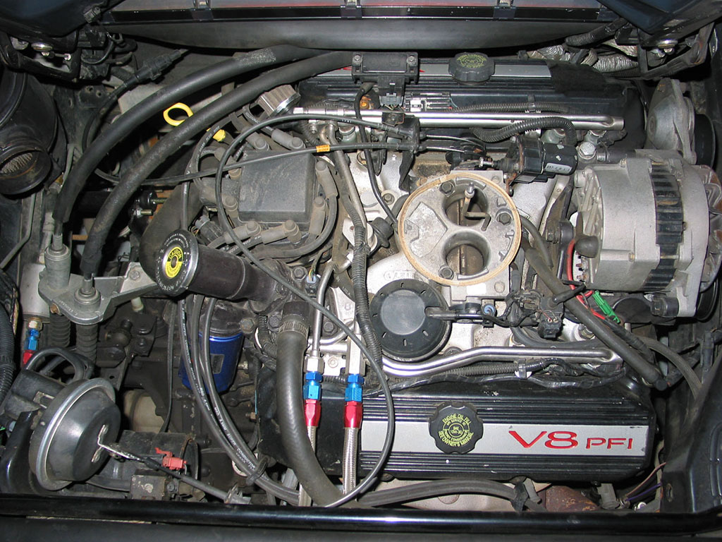 ***ADDED INFO***
Scans of my wiring notes: Left orignal size to keep it readable. NOTE: credit to Rockcrawl as this is where the original diagrams came from before I scribbled all over them.  ALDL Plug: 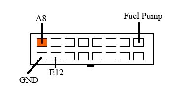 Highligthed areas are 'must use' connections (in most cases): NOTE: it was pointed out by ImperfectTruth that A7 is not highlighted and YES this is needed 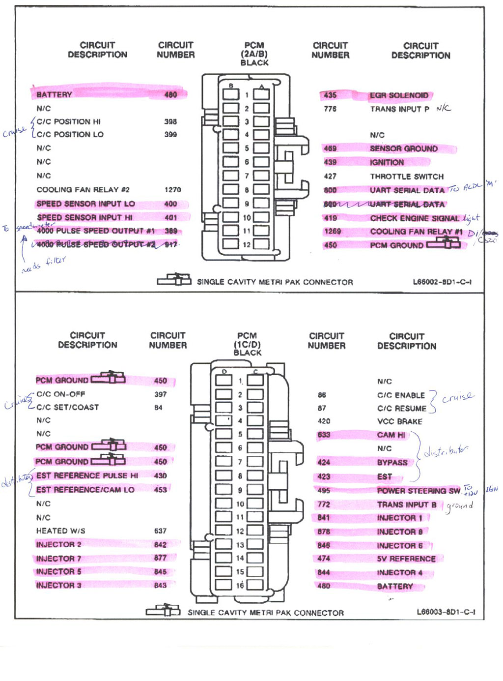 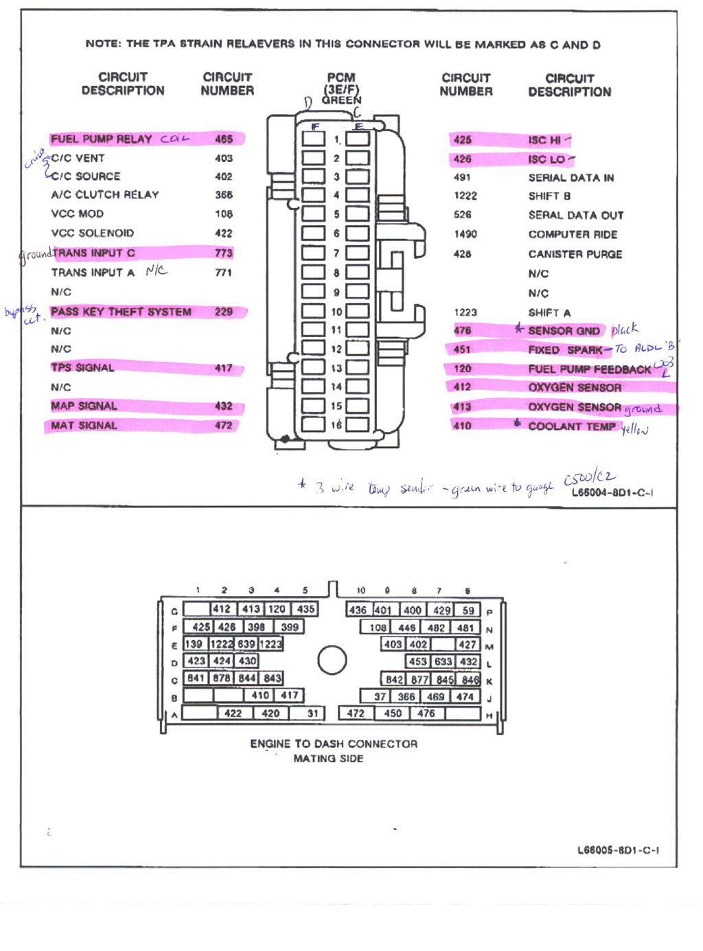 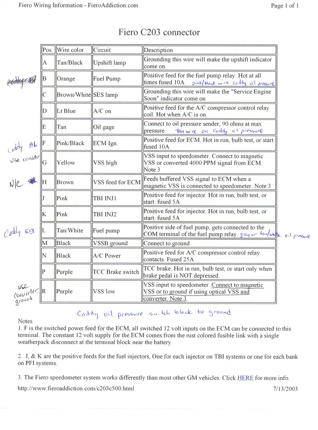 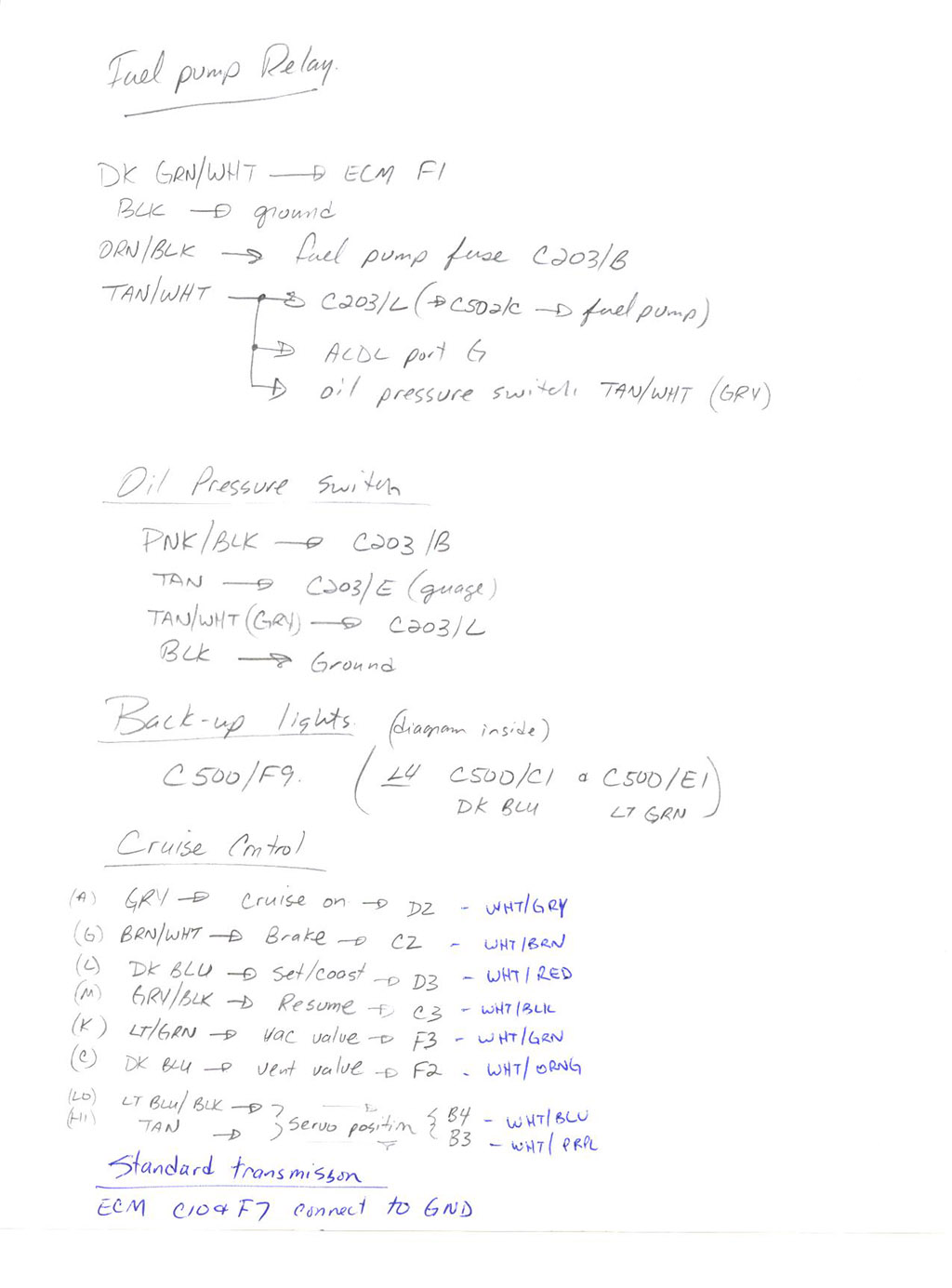 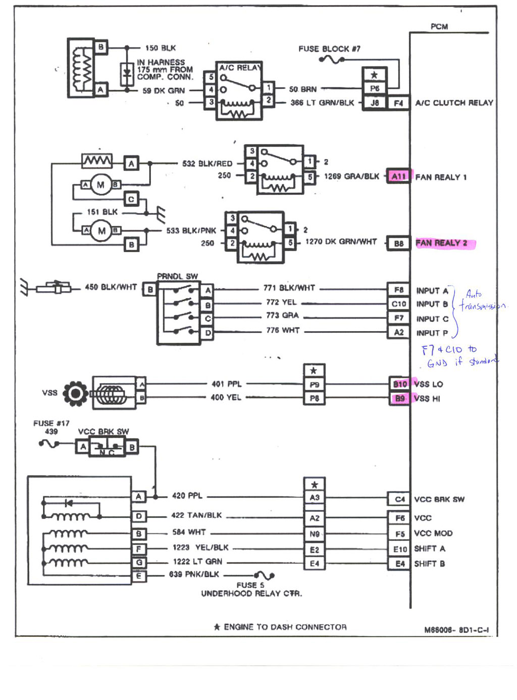 Note: there is a correction in the following for the grounds - it shows D5 as connected to ground when it should read D6: Thanks to olejoedad for pointing this out 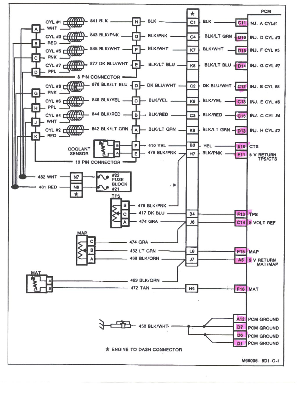 Note: there is a correction here for the EGR - the highlighted area is correct (EGR=A1): 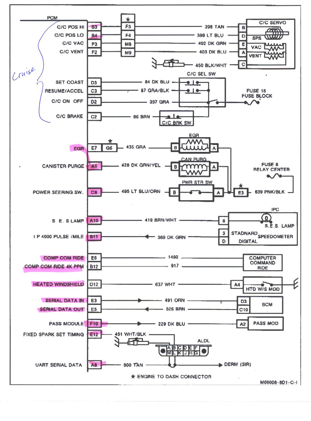 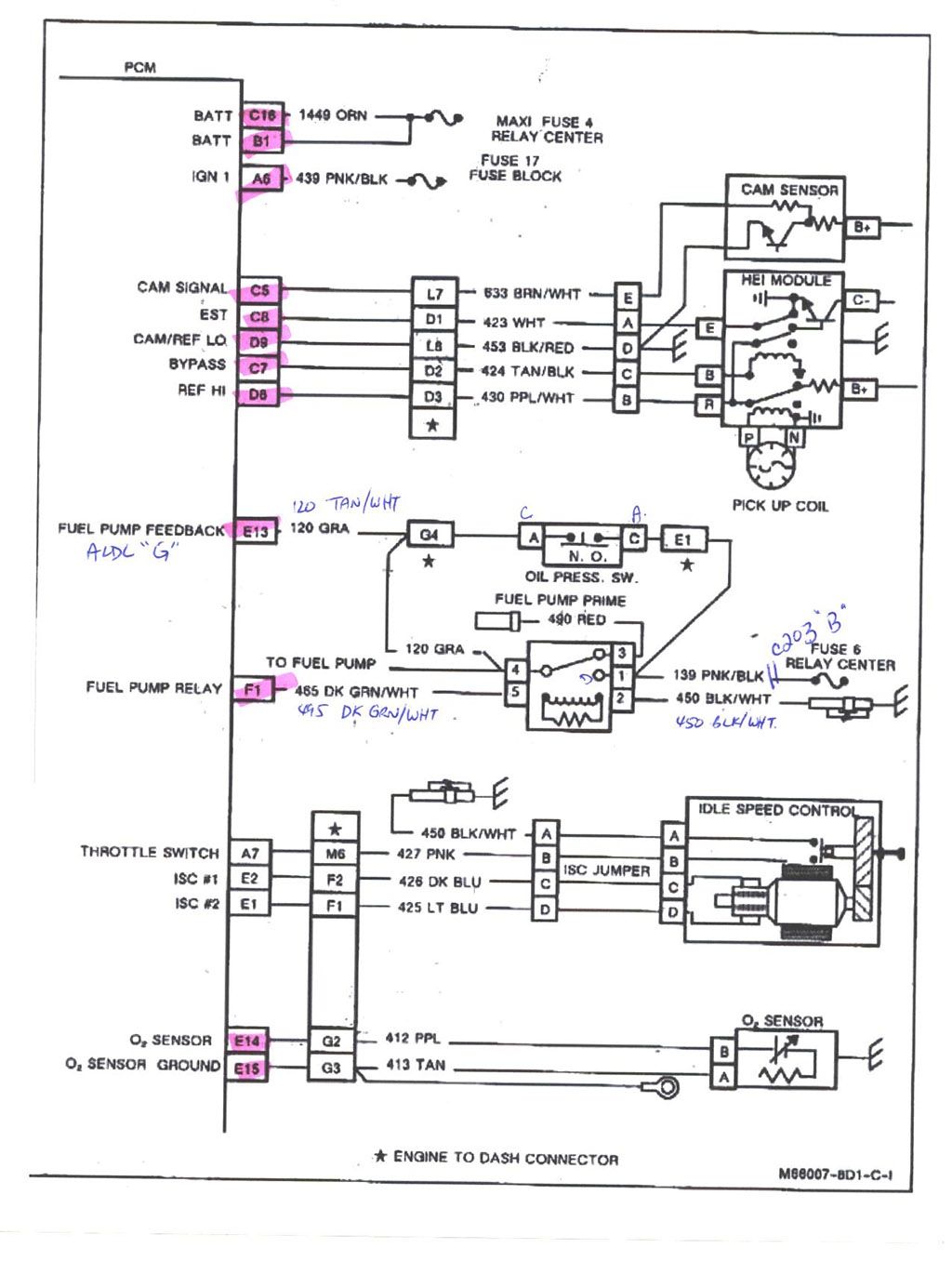 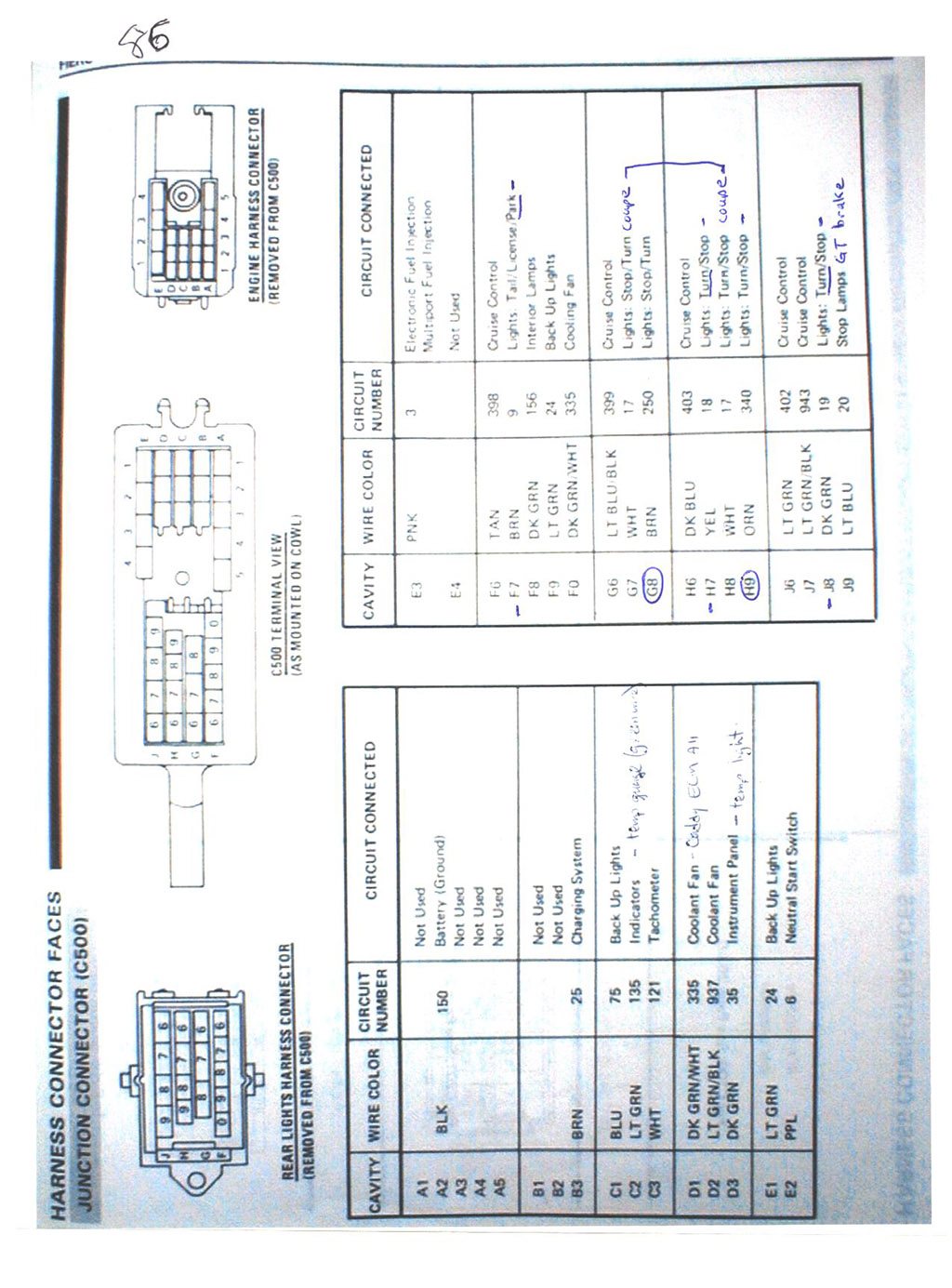 And here is a copy of the 92-93 service manual that I received courtesy of Fieroseverywhere: 92-93 4.9 Service Manual Just an FYI on how the ECM determines what gear the car is in F8, C10, F7 and A2 provide a binary code input to the ECM to tell it what gear the car is in - code 91 indicates a unknown code is inputted. SpECiFiCLlY: in this order of F8, C10, F7, A2 P = 0100 R = 0011 N = 1010 D = 1001 3 = 0000 2 = 0101 1 = 1100 So, in a manual car when you tie C10 and F7 to ground (the pins are tied high internal to the ECM) inputs 1001, which tells the ECM it's in drive. Technically speaking A2 is what GM is calling a parity bit and you have a 3 digit binary code. Hope that helps and answers any questions, Tim BIN files for the 2240 PCM (what I have) can be downloaded from here: https://drive.google.com/dr...AI0g4?usp=share_link NOTE: I do NOT recall if VATS has been disabled in these files or not - you will need to verify in Tunercat. [This message has been edited by Mickey_Moose (edited 02-11-2023).] |
|||||||||||||||||||||||||||||||||||||
|
|||||||||||||||||||||||||||||||||||||
|
Great writeup. Thanks! |
|||||||||||||||||||||||||||||||||||||
|
|||||||||||||||||||||||||||||||||||||
|
Awesome post! I converted this w/pics into a 2MB word document. With your permission, Tim, I can email it to anyone who needs it. |
|||||||||||||||||||||||||||||||||||||
|
|||||||||||||||||||||||||||||||||||||
|
The VATS (passkey) can be defeated with a VATS bypass module. They are available from Baker Electronix (e-bay store) for $25. There are two versions 30 Hz and 50 Hz. 30 Hz works for 91-93 and 50 Hz for 94. Edit to add website for Baker Electronix - http://mysite.verizon.net/vze7erz1/ [This message has been edited by sanderson (edited 02-03-2009).] |
|||||||||||||||||||||||||||||||||||||
|
|||||||||||||||||||||||||||||||||||||
Rofl... looks like someone got sick of having to answer my questions. Or at least didnt want to do it again.  Looks great, this information is absolutely invaluable. Thanks again. |
|||||||||||||||||||||||||||||||||||||
|
|||||||||||||||||||||||||||||||||||||
|
Great post - good work - a plus for you!!! |
|||||||||||||||||||||||||||||||||||||
|
|||||||||||||||||||||||||||||||||||||
|
plus from me also. About as complete as it gets right there, |
|||||||||||||||||||||||||||||||||||||
|
|||||||||||||||||||||||||||||||||||||
|
Please note that I have added a couple more pictures/info (to be 'more' complete): temp sensor, speedo converter and cruise. Also reorganized... ...and as soon as I find my passkey diagram, I will also add it to the post.  Feel free to 'share' this info with others, as it is meant to be shared and no secret (it's all been posted already, just not in one post).  [This message has been edited by Mickey_Moose (edited 02-03-2009).] |
|||||||||||||||||||||||||||||||||||||
|
|||||||||||||||||||||||||||||||||||||
|
You have a + from me, I am planning on gathering the 4.9 and other necessary items for this swap this summer into Fiero # 3. Joe Crawford Texas |
|||||||||||||||||||||||||||||||||||||
|
|||||||||||||||||||||||||||||||||||||
|
since i plan on doing a 4.9 in the future, a + from me. |
|||||||||||||||||||||||||||||||||||||
|
|||||||||||||||||||||||||||||||||||||
|
added ALDL plug diagram |
|||||||||||||||||||||||||||||||||||||
|
|||||||||||||||||||||||||||||||||||||
|
This thread should be called "4.9 wiring for Dummies" and I mean that in a good way! Thank you!!!!! |
|||||||||||||||||||||||||||||||||||||
|
|||||||||||||||||||||||||||||||||||||
|
Mickey Moose, I ran the main harness over the top of the engine when I did mine. It's butt ugly. Is there enough length in the Caddy harness to run the main harness down by the transaxle and then up to the firewall? |
|||||||||||||||||||||||||||||||||||||
|
|||||||||||||||||||||||||||||||||||||
If you run your wires like mine (see picture) there is enough length - a couple need to be made longer. Bascially, I run them all along the fuel rail (tuck way down), the rear side runs along the intake manifold and under the distributor. The front rail wires join up here and straight into the cabin. Any wires running to the C500 are run along the firewall following the harness that is there already. C500 wiring run along the strut tower to the motor (or along the firewall). Big thing is to lose a majority of the wire loom as it is bulky, just tape it up. Does that answer your question? |
|||||||||||||||||||||||||||||||||||||
|
|||||||||||||||||||||||||||||||||||||
Yup, That's what I needed to know. Probably going to build a new harness the right way when I get all the rest of the little things sorted out. |
|||||||||||||||||||||||||||||||||||||
|
|||||||||||||||||||||||||||||||||||||
|
...added: Passkey description and diagram AC wiring diagram 92-93 service manual ...to original post. I think that should be about everything now. Please let me know if I am missing anything. Tim |
|||||||||||||||||||||||||||||||||||||
|
|||||||||||||||||||||||||||||||||||||
That'd be me. I found that especially the fuel injector wiring diagram was much better in the 92-93 diagram. |
|||||||||||||||||||||||||||||||||||||
|
|||||||||||||||||||||||||||||||||||||
|
Mr Moose, I have read that the 88 4 cyl throttle cable is a direct fit to the 4.9.throttle body arm. Is the 87 4cy throttle cable also a direct hook up? I think I have read that the 87-88 2.5's cables were the same. Also would it be better for me to start with a 6cyl, or 4 cyl car for the basis of this swap? Better cooling maybe? Automatic or standard, I plan on using the 4T60E that was mated to a 4.9. On the liter side: I want to tell you how much I appreciate this write up you guys have done for us all. I cant give you another +. I have done lots of swaps in my life including a 2300cc Pinto engine into a VW van. The kit was called "The Pinto Bean". But this will be my first fuel injection implant. In 1962 my first car was a 1955 Pontiac Chieftan. I swaped in a 1957 Cadillac V8 , found in the Dallas paper for $75.00. All of my friends at school called it the "Caddie-Pon". Looks like my last swap will be a Caddie-Pon also. Joe Crawford Texas [This message has been edited by josef644 (edited 03-04-2009).] |
|||||||||||||||||||||||||||||||||||||
|
|||||||||||||||||||||||||||||||||||||
If they are the same part number I don't see why - but I can not comment if the 87 and 88 cables are the same since I never really looked into it. Maybe someone else can say they are. Does not matter what car you start with - however you will need the rad from a V6 car - I would also go with an automatic car since you will be using the 4T60E just to make things a little simpler (no clutch pedal to deal with and it already comes with the automatic shifter/etc). |
|||||||||||||||||||||||||||||||||||||
|
|||||||||||||||||||||||||||||||||||||
also transmission cooler lines and TCC brake switch/wiring |
|||||||||||||||||||||||||||||||||||||
|
|||||||||||||||||||||||||||||||||||||
...hence the 'etc' in my post  |
|||||||||||||||||||||||||||||||||||||
|
|||||||||||||||||||||||||||||||||||||
|
Thanks guys. Joe Crawford Texas |
|||||||||||||||||||||||||||||||||||||
|
|||||||||||||||||||||||||||||||||||||
|
...added information about the alternator wiring - now that should be everything (finally). |
|||||||||||||||||||||||||||||||||||||
|
|||||||||||||||||||||||||||||||||||||
I am updateing the word document for everyone. Looks like these three link are broken. Do you have the full url? Thanks! |
|||||||||||||||||||||||||||||||||||||
|
|||||||||||||||||||||||||||||||||||||
...fixed... |
|||||||||||||||||||||||||||||||||||||
|
|||||||||||||||||||||||||||||||||||||
|
Mickey_Moose, I'm trying to help out one of our new members with a temperature gauge problem. He bought a car with the 4.9 swap already done. The PO did not change out the temperature sensor. The car has a two wire sensor in it. The new owner has acquired the correct temperature sensor. Where do you get the connector for the new three wire sensor? I seem to remember I salvaged it off of an '88 Fiero harness. If you want to jump into the thread it is: https://www.fiero.nl/forum/Forum2/HTML/098585.html [This message has been edited by sanderson (edited 03-01-2009).] |
|||||||||||||||||||||||||||||||||||||
|
|||||||||||||||||||||||||||||||||||||
I got mine off of a 92 cavalier. There are tons of cars out there that use this type of connector. If you can't find one on the temp sender check the TPS. Wire colors probably wont match on the TPS connector but it will plug in. Not sure on the 88 fiero part. |
|||||||||||||||||||||||||||||||||||||
|
|||||||||||||||||||||||||||||||||||||
He found one at a junkyard. I think I used the 88 Fiero oil pressure sender/switch. I know I didn't get onre at a junk yard |
|||||||||||||||||||||||||||||||||||||
|
|||||||||||||||||||||||||||||||||||||
|
edited my post to include the temp sensor plug info - also, as you may already know, I posted in the "other" thread. |
|||||||||||||||||||||||||||||||||||||
|
|||||||||||||||||||||||||||||||||||||
|
added a FYI at the end on how the ECM knows what gear the car is in. [This message has been edited by Mickey_Moose (edited 03-14-2011).] |
|||||||||||||||||||||||||||||||||||||
|
|||||||||||||||||||||||||||||||||||||
|
Only one thing missing from this thread to be a compleat swap thread also is the information on the CV shafts needed to use the 4T60E. Hint Hint anyone, Sanderson? EDit to add: I found this info on FieroAddiction's site. Quoteing from his site, I hope he doesn't mind, any credit goes to him for the information: "For a 4T60E you can use the same left axle for a '89 Pontiac 6000 with 4T60 and light duty brakes on the left side, and a left axle for a manual Fiero on the right side. Some people have reported having problems with the Fiero axle on the right side, but they have always worked well for me." [This message has been edited by josef644 (edited 03-27-2009).] |
|||||||||||||||||||||||||||||||||||||
|
|||||||||||||||||||||||||||||||||||||
I used the '89 Pontiac 6000 axle on the left. On the right I used a 92 Old Silhouette with 4 speed auto and swapped a Fiero manual CV joint on the outer end. |
|||||||||||||||||||||||||||||||||||||
|
|||||||||||||||||||||||||||||||||||||
|
Which side of the 92 Old Silhouette did you get the parts from? |
|||||||||||||||||||||||||||||||||||||
|
|||||||||||||||||||||||||||||||||||||
Right side. I bought it new. Other early 90's minivans are the same if your'e going the junkyard route. |
|||||||||||||||||||||||||||||||||||||
|
|||||||||||||||||||||||||||||||||||||
|
4T60E Axles I found an archived thread from 2004 by member jeffndebrus that details how to get the correct size axles for a 4T60E. He also has several good pictures of these axels, and a good "how to" swap out the one hub end. I quote from his posting. Drivers,Left, side: "For your drivers side of the Fiero with 4t60e you can use a left axle for a '90 Pontiac 6000 with 4T60 and light duty brakes. It is a stock drop in part and works well." Passenger, right, side: "For the passenger side you have to use a GM axle part number 9572 which can be ordered by asking for a 1994 Pontiac Transport van right hand axle-4spd automatic 3800. The outer CV joint on this unit is too large to fit the Fiero hub/bearing assembly so it must be removed and exchanged for a Manual Tranny Fiero CV joint. ***Please Be Advised*** some axle remanufactureres are using smaller diameter axles so when you get your Fiero manual cv joint---make sure that the axle which it came off of is a 1.030in axle---NOT the smaller .85in which some are using.-the smaller cv joint will not fit on the minivan axle." A link to his thread: https://www.fiero.nl/forum/A...090219-2-057038.html |
|||||||||||||||||||||||||||||||||||||
|
|||||||||||||||||||||||||||||||||||||
|
Excellent post. Really good info here. The only thing missing were suggestions on what size serpentine belt to use and what fuel pump you ended up using. |
|||||||||||||||||||||||||||||||||||||
|
|||||||||||||||||||||||||||||||||||||
Good point on the fuel pump - will add that. As for the belt size, I can add that too, but this all depends on a number of factors (a/c compressor in the loop, the idler below the alternator, water pump idler size, etc). Anyways, original post updated - thanks for pointing that out. BTW - I left out the axle info out of the original post as others have replied on what to use (and I never done one myself). So thanks to josef644 and sanderson for the info. [This message has been edited by Mickey_Moose (edited 04-11-2009).] |
|||||||||||||||||||||||||||||||||||||
|
|||||||||||||||||||||||||||||||||||||
I believe the left side axle needs to come from an '89 Pontiac 6000. When I got mine from Carquest they didn't list a light duty brakes option for '90. |
|||||||||||||||||||||||||||||||||||||
|
|||||||||||||||||||||||||||||||||||||
It's a tight squeeze but I did manage to get the OEM Cadillac fuel pump into the tank. As you point out the belt length will vary depending on the details of the belt routing. I've got the Camaro tensioner with A/C and I'm running a 79" belt. It's a tight fit. I actually have to unbolt one side of the tensioner to get the belt on. But with a 79.5" belt it felt like the tensioner was fully extended. |
|||||||||||||||||||||||||||||||||||||
|
|||||||||||||||||||||||||||||||||||||
|
I went to RockAuto and looked up the fuel pump for a 1993 Deville, and a 1988 Fiero GT. Both used the AC Delco EP378 fuel pump, $78.79. 1987 Fiero Gt used a different one, EP240,$80.79. Two bucks difference. I was thinking that the 87 and 88 Fiero' both had the same enlarged just a bit fuel tank. I would think the FP access hole has to be the same. |
|||||||||||||||||||||||||||||||||||||
|
|||||||||||||||||||||||||||||||||||||
The fuel pump itself is bolted to the sender. So the physical size of the fuel pump is nearly irrelevant. Everything else being equal I would suggest the more powerful pump. With a fuel injected engine it's relatively harmless to have too much flow, but not enough can make your engine run dangerously lean. |
|||||||||||||||||||||||||||||||||||||
|
|||||||||||||||||||||||||||||||||||||
The Caddy pump I is used from a '92 Deville and the motor is about twice the diameter of an '88 Fiero V-6 fuel pump ( and I personally think size matters on electric motors). I had to grind on the fuel sending unit and enlarge the hole in the tank by about 1/16" on 1/2" of the circumference to get it in the tank. This project also entailed modfications to the fuel sending unit to mount the pump but I don't remember exactly what they were. It's a tight fit but it can be down. In your case I'd just pull the pump from the '93 Deville (whatever it is) and use it. If it's the same as a Fiero pump it's a piece of cake and you save $80. As I remember removing the gas tank on the Caddy was no big deal. |
|||||||||||||||||||||||||||||||||||||
|
|||||||||||||||||||||||||||||||||||||
My 4.9 is a 93, the Deville was a 91. And it is history. I'll just get me an 88 V6 fuel pump. [This message has been edited by josef644 (edited 04-14-2009).] |
|||||||||||||||||||||||||||||||||||||
|
|||||||||||||||||||||||||||||||||||||
Ohh I can't think of a reason that I would want to cut a larger hole in a gas tank. There are plenty of pumps that are only minimally larger, I would have gone with the Corvette or the Walbro before I started grinding on a gas tank. |
|||||||||||||||||||||||||||||||||||||
|
|||||||||||||||||||||||||||||||||||||
I had about 80 reasons to use the Caddy pump. The tank had been thoroughly cleaned with lacquer thinner and then hot water and TSP. There was no explosion risk. |
|||||||||||||||||||||||||||||||||||||
|
|||||||||||||||||||||||||||||||||||||
|
M Moose, Fieroseverywhere, I am starting to work on my harness for my 4.9 swap. I will be going to go get my 87 Coupe to put this in the next 8-9 days. I removed the body connector (two 7MM screws) from the wiring today, and started removing the black plastic harness protector stuff. I was looking at another guys thread requesting help about Pin 'C' on the round transmission plug. He was removing the two part rectangular connector with one small bolt in the center, and joining the ends back together. Are all you guys removing this? Is there room in the ECM area for this,or have you guys been mounting it in the engine compartment? If it needs to go, I am gonna start in on this and have it done when my care gets here. Thanks Joe Crawford [This message has been edited by josef644 (edited 04-26-2009).] |
|||||||||||||||||||||||||||||||||||||
|
|||||||||||||||||||||||||||||||||||||
Just remember to take your time - if you rush, you may make a mistake (and those can be tough to find later). Transmission plug - I have only done manual cars, so I can not comment on transmission plugs - maybe point me to the thread and I can have a look. The only 2 part connector I an aware of right now is the C500 - is that what you are refering to? My ECM is mounted in the stock location, you have to modify the plastic bracket a bit for it to fit (make a notch in the side for the top most plug) - I will see if I have a picture of mine I can post. Cheers, |
|||||||||||||||||||||||||||||||||||||
|
|||||||||||||||||||||||||||||||||||||
Here is a picture of it, I didn't know the number of it,or on any of my two printouts from Fiero Addiction, or this thread. They call it "Engine to Dash Connector Mating Side". I took the picture from the other guys thread. https://www.fiero.nl/forum/Forum2/HTML/100076.html Joe [This message has been edited by josef644 (edited 04-26-2009).] |
|||||||||||||||||||||||||||||||||||||
|
|||||||||||||||||||||||||||||||||||||
That is the caddy C225 connector. I used it as a quick connect for the engine harness. I still used the fiero passthrough for the firewall. When pulling my engine out I just disconnect the C225 and don't have to touch anything in the interior. I have a pinout for it though I believe there is also one on the fieroaddiction site. The pinout will only help so much if you decide to use it. You will still have to connect some wires where there are empty spaces (use the pins from the unused wires). It was more work during the install but should save time during maintence and repair. You can also use this instead of the fiero passthrough if you are willing to trim the firewall for clearance. Option 2: Cut the wires on the engine side of this connector, feed them through the firewall, connect to PCM connectors and C203. Cleaner looking install if that is what you are going for. [This message has been edited by Fieroseverywhere (edited 04-26-2009).] |
|||||||||||||||||||||||||||||||||||||
|
|||||||||||||||||||||||||||||||||||||
Option 2 : Use the ECM mount bracket from an 87-88 Duke. Will fit with no modifications except for screw holes to mount it. |
|||||||||||||||||||||||||||||||||||||
|
|||||||||||||||||||||||||||||||||||||
|
Fieroseverywhere you have this C225 in the engine bay? I have purchased a 1987 Coupe for my 4.9 swap. I had already purchased me an 87-88 ECM tray. I have all the wiring diagrams. Joe [This message has been edited by josef644 (edited 04-27-2009).] |
|||||||||||||||||||||||||||||||||||||
|
|||||||||||||||||||||||||||||||||||||
I usually cut that out. If you cut the wires right at that block, most of the wires will be long enough to reach the ECM in the stock location (provided you remove all the tape and reorganize them, there are only a couple of wires that need to be lengthened) - I wire the car in such a way I can remove the engine harness the same way as the stock Fiero one (unplug the ECM, C203 and disconnect the grounds and pull though the bulkhead). BTW - here is the picture of my ECM (the thing taped to the front is my passkey bypass) - also the white plug near the C203 is for my cruise control (4.9 controlled):  [This message has been edited by Mickey_Moose (edited 04-27-2009).] |
|||||||||||||||||||||||||||||||||||||
|
|||||||||||||||||||||||||||||||||||||
I resized your mounted ECM picture so it would be easier for viewing. I hope you dont mind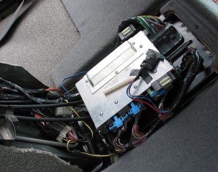 Joe |
|||||||||||||||||||||||||||||||||||||
|
|||||||||||||||||||||||||||||||||||||
Yes. I used the fiero passthrough for the firewall. The C225 is bolted to the firewall on one of those tabs I no longer needed. Here is a pic before loom and such.. 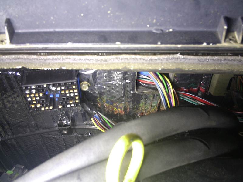 I just unbolt that connector to remove the engine. My engine harness is actually 2 pieces just like the original caddy one. [This message has been edited by Fieroseverywhere (edited 04-28-2009).] |
|||||||||||||||||||||||||||||||||||||
|
|||||||||||||||||||||||||||||||||||||
|
Neet! |
|||||||||||||||||||||||||||||||||||||
|
|||||||||||||||||||||||||||||||||||||
The great auto axle debate:
OR...
|
|||||||||||||||||||||||||||||||||||||
|
|||||||||||||||||||||||||||||||||||||
It's pretty obvious that a drop-in Pontiac 6000 axle for the left side is easier and cheaper than swapping a Fiero CV joint onto a minivan axle. Rockcrawl recommends the Pontiac 6000 axle for the left side. Nobody on PFF has reported a problem with the Pontiac 6000 axle. |
|||||||||||||||||||||||||||||||||||||
|
|||||||||||||||||||||||||||||||||||||
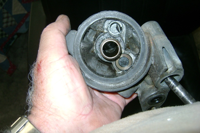
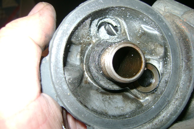
1. In this picture there is a green connector,to the left side of the alternator. The wire goes in, then out of the green part. Then ends up plugged into the alternator in a black plastic plug. Whats the green connector for? Where does it connect to? I cant find reference to it in my wiring diagrams. I borrowed Mickey Moose's picture: 2. All of these "Cruise Control" wires and connectors, can I just clip them out of the harness as I am not going to use these. Joe [This message has been edited by josef644 (edited 06-21-2009).] |
|||||||||||||||||||||||||||||||||||||
|
|||||||||||||||||||||||||||||||||||||
IIRC the green plug only has the on wire in it on the one side - this is used for grounding out the alternator to disable it during the proceedure to set the timing. If you are NOT using cruise, you can remove them from the harness - for unused wires on the ECM plugs I just grab them and yank the pin out of the plastic connector. ONLY DO THIS after you have started the motor and it is running, the pins are damaged when you do this and can not be put back in. But feel free to yank the cruise wires, just double check before you remove them. |
|||||||||||||||||||||||||||||||||||||
|
|||||||||||||||||||||||||||||||||||||
|
Great information. I had run into a little snag on my harness yesterday. My 93 engine still had its injector wiring part of the harness on the injectors. My 91 harness uses two connectors, one for the even bank, and one for the odd bank. The 93 only has one connector on the injector group harness for all 10 wires. I still had 90% of the 93's harness in the garage, and I think I can splice in the 93 injector connector part into the 91's engine group wiring harness. There was only one difference in the color of the wiring to deal with. I had access to the 92-93 wiring off of your thread from FieroAddiction, and Alldata.com, as well as the available 91's harness diagrams. I am gonna lay all of this out on my 4.9 Wednesday morning, and get this all sorted out in a neat and orderly fashion. [This message has been edited by josef644 (edited 06-22-2009).] |
|||||||||||||||||||||||||||||||||||||
|
|||||||||||||||||||||||||||||||||||||
Wouldn't it just be easier to use the other injector wiring harness? The less splicing the better (less chance of a screw up, less chance of there being a problem in the furture, etc). but that is just me. |
|||||||||||||||||||||||||||||||||||||
|
|||||||||||||||||||||||||||||||||||||
I don't have access to the other harness on the old 91 Deville engine. How do I remove the injector harness from the injectors? I havent found that in the books, or on AllData.com. |
|||||||||||||||||||||||||||||||||||||
|
|||||||||||||||||||||||||||||||||||||
Push the metal 'ring' in and pull off... |
|||||||||||||||||||||||||||||||||||||
|
|||||||||||||||||||||||||||||||||||||
Just did one, and it worked great. Thanks Joe |
|||||||||||||||||||||||||||||||||||||
|
|||||||||||||||||||||||||||||||||||||
|
Congrats Josef on getting this far. I have been having problems with my computer deleting all my cookies so I'm not sure which threads have been updated and which have not. I'm not sure if you saw this yet or not but when doing the wiring for the injectors be sure to use the 92-93 diagrams Mickey posted here in this thread. You will immediately notice a difference between those and the 91 diagrams listed on fieroaddiction.com. The 92-93 diagram actually have everything as it should be. Be careful of one thing though. There are two wires that are the same on the harness (same color). Make sure you put them in the correct spot and check them with a multimeter to be sure. I don't recall exactly but I remember having a problem with that. If you don't find those diagrams here I can e-mail you a copy also... if I haven't already. |
|||||||||||||||||||||||||||||||||||||
|
|||||||||||||||||||||||||||||||||||||
|
There are many of the same colored wires in the 91 harness. Lots of green and green w/wt stripe. I have been checking them one at a time with the meter. I also set up a battery charger and used a test light to find the correct holes in the ECM plugs faster. If the light is on I had the correct hole. As I removed the caddie C225 connector I soldered the wires back togeather an put heat shrink on them. Every wire was done one at a time, and ohmed out after the soldering. Took a while, but I dont want any errors or crossed wires to figure out later. This has really not been real bad so far. I now know each wire , and have marked all of the loose ends with tape as to where they should be connected once merged with the C203- C500 harness. I have one connector I don't know where it goes yet, but I am sure once I set this on the engine and start laying it al out I will find the empty sensor or what ever. It was in the engine harness, but was not a part of the ECM plugs wires. And yes there was two wires different than what was in the 91 diagrams, the # 3, and # 4 in the diagrams were different. I used the correct ECM connector socket to establish the correct injector wire, not the wire color. Joe [This message has been edited by josef644 (edited 06-24-2009).] |
|||||||||||||||||||||||||||||||||||||
|
|||||||||||||||||||||||||||||||||||||
Can you post a pic of it? Sounds like you got this all locked down. No too tough, just time consuming. You'll be driving before you know it. |
|||||||||||||||||||||||||||||||||||||
|
|||||||||||||||||||||||||||||||||||||
|
The wire colors are Lt Green, Dk Green, and the black wires come to a common grounding eye. Both had the insulation toasted right at the connectors. Both have a light blue " gruved rubber band seal". If you want an un compressed photo PM me your home e-address and I'll get it on the way. I have to compress all pictures before posting here on PFF 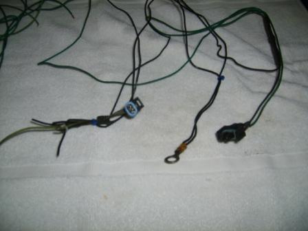 Joe |
|||||||||||||||||||||||||||||||||||||
|
|||||||||||||||||||||||||||||||||||||
|
Yea send me the full size pic. Can't quite tell what it is. The email tab right here...........^^^^ has the right address. Is that a part of the caddy harness or fiero? Oh wait, blue rubber seal. I was looking at the other plug..... checking... OK. I just confirmed. I'm not entirely sure which connector that is. I did not use it on my harness. This leaves a few options though... AC Cruise Auto trans Possibly the stock caddy CTS connector. (this needs to be switched for a 3 wire connector anyways) If its part of the fiero harness then it could also be other options. I started with an 85GT with no AC, cruise, and had a V6 so it could be something to do with that. I'll keep checking and see what I can come up with. Hopefully someone else will be able to chime in also.  [This message has been edited by Fieroseverywhere (edited 06-25-2009).] |
|||||||||||||||||||||||||||||||||||||
|
|||||||||||||||||||||||||||||||||||||
|
It was part of the Caddie harness but was not connected to the ECM plugs or was not connected to (spliced to) a sensor that was. There were two grounding eyes in the Caddie harness, this was one of the two. I'll send you a picture later today. I have some chores do attend to before it gets 103* again. Heat index was 108 here yesterday. Joe [This message has been edited by josef644 (edited 06-25-2009).] |
|||||||||||||||||||||||||||||||||||||
|
|||||||||||||||||||||||||||||||||||||
|
As asked - which harness?? If all your sensors on the 4.9 are plugged in, don't worry about these (don't forget about the plugs on the transaxle). BTW - the ECM plugs are marked which pin is which (look close and you will see the pin numbers stamped) - your method is a good ideal, but I am too lazy to keep getting up and down to go to the engine bay to move the battery (plus I am getting too old for that). |
|||||||||||||||||||||||||||||||||||||
|
|||||||||||||||||||||||||||||||||||||
|
Sorry , I should have said that it was part of the 91 Deville harness, the one I am using for my swap. I do have 90% of the 93 Deville's harness. They cut it all off at the firewall. 107* outside right now. Fieroseverywhere I just sent the unresized photos. Joe [This message has been edited by josef644 (edited 06-25-2009).] |
|||||||||||||||||||||||||||||||||||||
|
|||||||||||||||||||||||||||||||||||||
|
I just finally got my speedo to work. Thought I'd toss the info out here for those that have problems like I did. Basically I bought the signal clamp circuit from fieroaddiction, wired it in and... nothing. Speedo would zero out but never moved. SO I decided to make my own circuit. Then I checked the wiring a dozen or so times. Still nothing. Long story short the problem ended up being a bad output on the PCM. Good thing for us there are 2 on the caddy PCM. So if your speedo doesn't work when you use output B11... switch to B12. Honestly, I'm just glad to know how fast I'm going. Hey Mickey, Want to add this to the first post with the other speedo info? Could come in handy to some later. [This message has been edited by Fieroseverywhere (edited 07-02-2009).] |
|||||||||||||||||||||||||||||||||||||
|
|||||||||||||||||||||||||||||||||||||
|
Also on speedo problems don't overlook the radio fuse - don't ask me how I know |
|||||||||||||||||||||||||||||||||||||
|
|||||||||||||||||||||||||||||||||||||
How do you know? Sorry, I just had to. |
|||||||||||||||||||||||||||||||||||||
|
|||||||||||||||||||||||||||||||||||||
Just wanted to toss something out there on this... For most fieros this is the correct way to wire this in. The only problem I found comes for those who have fixed their pegging temp gauge. Here is a link on how to do the fix... http://www.fierosails.com/tempgage.html You have to switch the 2 pairs of wires to correct this mis-wiring from the factory. Problem is for us 4.9 guys we have switched out our CTS's for a 3 wire unit. This makes it a little harder to determine which wires to switch. To make matters worse the 3 wire unit does not run a temp light so technically there is one wire missing from the equation. The two wires that need to be switched in the gauge cluster do not change. While facing you gauges, the left connector on the back pin 11 needs to be switched with the right connector pin 13. This is the same for all fieros that have this problem. The two wires in the engine bay that need to be switched are located at the C500. C2 (dk grn/wht wire V6, tan wire L4) and D3 (dk grn wire) are the ones in question. In a fiero with a stock CTS you simply switch these wires at the connector. Option 1: In a 4.9 fiero you probably won't even have the wire in D3 hooked to anything... unless you are lucky enough to have the caddy head temp sensor on your engine and decided to use it. You probably hooked the CTS wire to C2 to run the gauge. If you, instead, connect pin "C" of your CTS to D3 of the C500 instead and switch the 2 wires at the dash connectors your temp gauge will not peg on startup anymore. Option 2: An even easier way to take care of this is to remove and tape up the Dk grn/yellow wire from G1 or G2 (varies based on year) from the ignition switch connector. This will eliminate the bulb test feature. Since most of us are not using a temp light anyway it won't make a difference if we take care of it this way. If you are running the caddy head temp sensor use option 1. Most of my fieros I don't even bother with this fix. The temp gauge in my 4.9 though, sticks when it pegs and drives me crazy. I just had to fix it. Anyways, thought I'd share. [This message has been edited by Fieroseverywhere (edited 07-02-2009).] |
|||||||||||||||||||||||||||||||||||||
|
|||||||||||||||||||||||||||||||||||||
|
Does the distributor 12v supply need to be switched or can I hook it to the battery distribution terminal under the c500? Also how has everyone connected the tach lead? What source did you use for the connector? |
|||||||||||||||||||||||||||||||||||||
|
|||||||||||||||||||||||||||||||||||||
For dist power I used the pink wire from the C500 (pin E3). For tach the white wire from C500 (pin C3). For the tach connector @ the coil I used a second dist power connector and shaved off the tab that keeps it from being used on the tach side. You can also find any GM vehicle with HEI ignition and a Tach and swipe a connector from there. |
|||||||||||||||||||||||||||||||||||||
|
|||||||||||||||||||||||||||||||||||||
tach lead = find an HEI distributor in the junk yard that has a tach lead on it and use that one - the BAT lead can be modified to work in the tach position (so I have heard). [This message has been edited by Mickey_Moose (edited 08-24-2009).] |
|||||||||||||||||||||||||||||||||||||
|
|||||||||||||||||||||||||||||||||||||
Good info how about the 12 volt lead should that go straight to the battery or should it be switched? The FSM really does elude to either. I actually found a website that has the tach connector and the 12v connectors and a bunch of other GM stuff. Here is the link. It's fairly inexpensive and less than it would cost me to drive and hunt for one. http://www.repairconnector....subcatid/0/id/293731 [This message has been edited by Carrluvr (edited 08-24-2009).] |
|||||||||||||||||||||||||||||||||||||
|
|||||||||||||||||||||||||||||||||||||
No not always hot. The pink one from the C500 is your ignition on wire. |
|||||||||||||||||||||||||||||||||||||
|
|||||||||||||||||||||||||||||||||||||
|
Mickey_M or Fieroseverywhere, I am adding my C500. I see where the pink wire "J" & "K" are the injector feeds. I only have one of these as my car was a 2.5 Duke in its prior life. Can I feed both banks of four injectors off of this one feed, or do I need to locate/create a second injector feed for my red/white 4.9 injector harness? Is this asking to much for one wire to feed all eight injectors? Thanks Joe Crawford [This message has been edited by josef644 (edited 09-07-2009).] |
|||||||||||||||||||||||||||||||||||||
|
|||||||||||||||||||||||||||||||||||||
I assume you mean C203. Under the console next to the shifter? While it might be possible to run both banks off on one wire if you up the fuse, I think its better to add the second wire. The C203 should have both wires running to it from the fuse panel. The 2.5 cars only have one wire coming out though. Just add the one pin and your golden. Double check that there are 2 fuses in place. I think the ALDL has the same pins so you probably have extras somewhere. Not that a quick trip to the yard cant fix it either way. |
|||||||||||||||||||||||||||||||||||||
|
|||||||||||||||||||||||||||||||||||||
What here said - the C203 opens up like a clam shell so it is easy to remove/add wires with pins. |
|||||||||||||||||||||||||||||||||||||
|
|||||||||||||||||||||||||||||||||||||
|
Yep, I mean the C203. I am seeing so many wires I get corrrn-fused. i see wires in my sleep!! Thanks for the speedy reply to both of you. I will not be able to get any progress done this week as I am trying to play catch up with the mowing here. I will have Satuerday & Sunday off to get some more work done on the coupe. We have three plugs connectors on the 4t60E. The round one is for the shift solinoids and lock up converter, the 4 wire flat one is for the ECM gear position information. The third one is a 5/6 wire connector for the start signal imput and backup lights. Position "C on that connector is labeled "Brake Switch". Is this a brake depressed signal, like for the brake light, or the brake released signal as for the lock up converter and cruise control. In you debt Joe Crawford [This message has been edited by josef644 (edited 09-08-2009).] |
|||||||||||||||||||||||||||||||||||||
|
|||||||||||||||||||||||||||||||||||||
|
added some more info to first post regarding the cruise control from Fieroseverywhere. |
|||||||||||||||||||||||||||||||||||||
|
|||||||||||||||||||||||||||||||||||||
|
To keep everything together, first posted edited to add: 1) proceedure for deleting the oil cooler as originally posted by josef644: https://www.fiero.nl/forum/F...L/077299-4.html#p158 2) a picture of a semi completed wiring harness |
|||||||||||||||||||||||||||||||||||||
|
|||||||||||||||||||||||||||||||||||||
|
Just added some info on an a/c delete pulley, and idler pulley (which seemed to be missing)...and a bump for the new comers. [This message has been edited by Mickey_Moose (edited 01-24-2010).] |
|||||||||||||||||||||||||||||||||||||
|
|||||||||||||||||||||||||||||||||||||
|
Just a bump so I can add this to my favorites here on PFF |
|||||||||||||||||||||||||||||||||||||
|
|||||||||||||||||||||||||||||||||||||
|
Bump for an excellent reference tool! |
|||||||||||||||||||||||||||||||||||||
|
|||||||||||||||||||||||||||||||||||||
|
bump for the new comers... |
|||||||||||||||||||||||||||||||||||||
|
|||||||||||||||||||||||||||||||||||||
|
M_M I had ordered some compressor 'O' rings this last weekend. I only had one 'O' ring on my compressor. They arrived today, and were sealing washers, not compressor port 'O' rings. I spent about two hours on the net looking for a number to try to look up to get the correct ones. I located OEM # 02724674, which is AC Delco #1530169. I called O'Rrilly's in Huntsville, TX They had 9 in stock. 83 cents each. I drove the 32 miles each way and bought me 4 of these. If I was asking for these by application, 91 Cad Deville, AC & heating, compressor seals, etc they were not listed. I found this OEM number at http://gmpartsgiant.com/ This was a difficult item to find. I had been to 4 different parts houses trying to find these, I took my one in my possession, most said they had nevere seen one like these, as they are sort of oval shaped. The guys at O"Riley's didn't even know they had these until I gave them the AC Delco number. This number was hard to find and might be helpful to someone else trying to AC their 4.9 using the Caddie's compressor.  Joe [This message has been edited by josef644 (edited 06-04-2010).] |
|||||||||||||||||||||||||||||||||||||
|
|||||||||||||||||||||||||||||||||||||
|
Thanks for the info Joe and posting it in this thread - nice to try and keep all the info in one place. |
|||||||||||||||||||||||||||||||||||||
|
|||||||||||||||||||||||||||||||||||||
|
What a great post, useful and informative. thank you for taking the time to post your work and share your reference material. You saved me hours of work |
|||||||||||||||||||||||||||||||||||||
|
|||||||||||||||||||||||||||||||||||||
|
I redid my wiring diagrams. They were produced almost entirely using information from this thread so credit is due to Mickey_Moose and others that helped get this out there. These are specifically for a 92' 4.9 single O2 into an 87' Fiero Gt Manual. Hope they are of use to someone. This is the second iteration and I have worked out the bugs but as always use at your own risk. http://depositfiles.com/files/zymub91vy [This message has been edited by Dizzixx (edited 08-27-2010).] |
|||||||||||||||||||||||||||||||||||||
|
|||||||||||||||||||||||||||||||||||||
Very nice work Dizz!! These is the first true conversion diagrams I have ever seen. Complete will all the pin #'s and wire colors. Very nice!! On the shift light. There may be a way to make it work but would require a change to the auto trans shift tables. I was able to make it sort of work at one point. The issue was it was way off for when it came on. I used the VCC pins on the PCM to accomplish this (F5 & F6). One of those wires would turn on the light for 1st and 2nd, the other did 3rd and 4th. I finally had to disconnect it. Light kept coming on at idle and stayed on in 4th gear. |
|||||||||||||||||||||||||||||||||||||
|
|||||||||||||||||||||||||||||||||||||
|
Had to go through it pin for pin today for myself. I caught two minor things. A)Two of the pins on the TPS were labeled wrong. B) ECM B1 is always hot with C16 through the fusible link. I have edited my previous posts download link to reflect this. |
|||||||||||||||||||||||||||||||||||||
|
|||||||||||||||||||||||||||||||||||||
|
info from Dizzixx and Fieroseverywhere added to the first post to try and keep all the info in one spot. Thanks guys... marked with: ***ADDED INFO*** [This message has been edited by Mickey_Moose (edited 09-22-2010).] |
|||||||||||||||||||||||||||||||||||||
|
|||||||||||||||||||||||||||||||||||||
|
Just added some info about the idler pulley near the water pump to the original post. |
|||||||||||||||||||||||||||||||||||||
|
|||||||||||||||||||||||||||||||||||||
|
your awesome mickey id give you a +1 but i already did a while ago ;-) |
|||||||||||||||||||||||||||||||||||||
|
|||||||||||||||||||||||||||||||||||||
|
Edit: I have a 93 Deville ECM controlling my 94 4.9L/4T60E (with the proper sensor and tranny wire corrections) I just bought a scanner that does both OBD2 and OBD1 and when I connect it to my 88 4.9 Fiero, and turn the key to the ON position, I get a "Vehicle not responding...". I checked the connections and I also checked the scanner on a different car (although it was an OBD2 car) and everything is fine on that front. So, now it's time to look into the Fiero wiring. In the diagram below: 1) I'm assuming that we're looking at the ALDL connector as though it is mounted in the factory postion and we are sitting on the dashboard. Is that correct? 2) I checked the A8, ground, and E12 connectors that they all have continuity at the ECM positions, but I don't know where the "fuel pump" connector should be reading from. There is a "fuel pump feedback" pin on E13 of the ECM, and there is "fuel pump relay" pin on F1. Are either of those the "checkpoint" for checking what "fuel pump" signal the ALDL is getting? thanks, -Tim  Edit: I just noticed on the diagrams I have for a 91-93 Deville (and on the schematics in the first post as well) it shows on the ALDL that A position connects to GND B position connects to E12 M & L positions connect to A8 which also goes to DERM (whatever that is) [This message has been edited by BigGuyTinyCar (edited 04-08-2011).] |
|||||||||||||||||||||||||||||||||||||
|
|||||||||||||||||||||||||||||||||||||
|
The fuel pump circuit is for manualy priming the pump (connect +12v to that pin). Unless someone put it in there for your 4.9 swap it probably doesn't have one. Especially if they used the caddy ALDL connector and/or the caddy fuel pump relay. E12 is used for setting the timing. A8 is for scanner data (I wired it to both pins M & L). A is... obvious. |
|||||||||||||||||||||||||||||||||||||
|
|||||||||||||||||||||||||||||||||||||
Thanks. Mine appears to be wired correctly, but it won't communicate with my scanner for some reason. It doesn't appear to be a scanner connection problem because it says, "Link Initialization established", but then quickly comes back with "Vehicle not responding". What the heck is DERM? [This message has been edited by BigGuyTinyCar (edited 04-09-2011).] |
|||||||||||||||||||||||||||||||||||||
|
|||||||||||||||||||||||||||||||||||||
DERM - Diagnostic energy reserve module. In particular this device is part of the SIR, or supplemental inflatable restraint system. One function of it is... In the event of a front end crash where voltage is lost the DERM will make sure the airbags can still function. This is done by way of a 36 volt reserve loop. The DERM can also detect malfunctions in the SIR system, record malfunctions, notify driver of malfunction (by way of a "inflatable restraint" light), or record system status during a frontal crash. Obviously not necissary unless you installed airbags in your fiero. [This message has been edited by Fieroseverywhere (edited 04-09-2011).] |
|||||||||||||||||||||||||||||||||||||
|
|||||||||||||||||||||||||||||||||||||
|
wrong thread lmao [This message has been edited by hookdonspeed (edited 06-15-2011).] |
|||||||||||||||||||||||||||||||||||||
|
|||||||||||||||||||||||||||||||||||||
|
I thoroughly enjoyed reading this thread and was inspired to do a 4.9L swap. Lots of great info posted here. Ho0wever these Caddy engines seem to be getting hard to find in solid shape. Sure you can get the 130K+ powertrains but try to get one at 80K or less and your are S.O.L. I've been looking for quite some time with out success. Maybe I'll get lucky and find a recent low miles wreck but that takes me back to the 3800's that appear to be available. |
|||||||||||||||||||||||||||||||||||||
|
|||||||||||||||||||||||||||||||||||||
|
I have a question concerning the pinouts and diagrams - Per Schematic M66006-8D1-C-1 (on the first page of this thread), ECU grounds are D1, D5, D7 and A12 - BUT per the MetriPak pinout for connector C/D, ECU grounds are located at D1, D6, D7. My C/D connector has D1, D6 and D7 as grounds. Should I leave the connector the same (D6) or re-pin it for D5 as the schematic indicates? Stickpony reprogrammed the ECU. Thanks for the input. |
|||||||||||||||||||||||||||||||||||||
|
|||||||||||||||||||||||||||||||||||||
I wouldn't worry about 130k - I have found through experience that these things are fairly bullet proof. That being said, if you are still on the fence I would probably lean more towards the 3800SC (power and revs are better) - but you need to decide on which side of the fence you want to be on.
Which ECM are you using and what did Stickpony program for? The diagrams are for a 91 Deville setup - other models and years vary. So if you are using the 2240 ECM and have the EPROM programmed as the 91 Deville use the diagrams as posted - otherwise you will need to make the changes to match your setup. [This message has been edited by Mickey_Moose (edited 08-16-2011).] |
|||||||||||||||||||||||||||||||||||||
|
|||||||||||||||||||||||||||||||||||||
|
The EPROM is programmed for a 91 deville, the ECU was a remanned (by AC/Delco) unit with GM# and ACD# 88999176. The car was a 91 Deville as far as we can tell. The C/D plug is pinned as the MetriPak pinout shows, I just questioned the discrepancy between the MetriPak pinout and the ECU wiring schematic relative to D5 (on the wiring diagram) and D6 (on the MetriPak pinout). Your clarification will help out alot. |
|||||||||||||||||||||||||||||||||||||
|
|||||||||||||||||||||||||||||||||||||
The 92-93 diagrams correct for this discrepancy. D1, D6, D7, and A12. There were a few other corrections also. As far as I've ever been able the tell all of the corrections work for all 91-93 devilles/fleetwood/60 special no matter what they are wired for. The only real difference is in the injector harness itself, which is slightly differernt. http://captfiero.com/caalon...20PCM%20diagrams.pdf Hope this helps. [This message has been edited by Fieroseverywhere (edited 08-16-2011).] |
|||||||||||||||||||||||||||||||||||||
|
|||||||||||||||||||||||||||||||||||||
|
Thanks for the info and the link, it helps out greatly. This is such a good thread, I hope that this info helps someone else. Joe |
|||||||||||||||||||||||||||||||||||||
|
|||||||||||||||||||||||||||||||||||||
|
Ok, my bad - I don't think the read the post correctly (or understood it) - but I do now and see the issue. I have always wired it according the MetriPak pinout and never really paid any attention to the actual wiring diagrams much. I will make a note of this in the first post. Thanks for pointing that out. |
|||||||||||||||||||||||||||||||||||||
|
|||||||||||||||||||||||||||||||||||||
|
I probably would not have noticed it either, but on the schematic the D5 was fuzzy and I couldn't tell if it was a '5' or a '6', so I went to the pinout............ Good thread, quite the asset for the Fiero Community. Thanks for the help. |
|||||||||||||||||||||||||||||||||||||
|
|||||||||||||||||||||||||||||||||||||
|
Another question, this time concerning the speedometer conversion circuit...... I have seen and used diagrams very similar to this when wiring up the VSS on the 4T65E-HD used on the 3800SC - the circuit is the same except for the diode on the switched 12v lead (C203F). Is the diode needed in the circuit when doing the 4.9/4T60E swap? Thanks for the help. Joe Edit to remove link. [This message has been edited by olejoedad (edited 08-20-2011).] |
|||||||||||||||||||||||||||||||||||||
|
|||||||||||||||||||||||||||||||||||||
|
Link doesn't work. To answer the question though I have never needed to use a diode in this circuit. Just the one .1 uf capasitor, the 22k resistor, and the 1k resistor. The diagram in the first post is correct as far as I know and should work for all engine swaps (unless you have non-fiero gauges). [This message has been edited by Fieroseverywhere (edited 08-20-2011).] |
|||||||||||||||||||||||||||||||||||||
|
|||||||||||||||||||||||||||||||||||||
|
Thanks. Appreciate your prompt reply. Joe |
|||||||||||||||||||||||||||||||||||||
|
|||||||||||||||||||||||||||||||||||||
|
Another question as I finish the wiring (and my notes) for this 4.9/4T60E swap into an 88 Formula - Neutral Safety Switch - 7 connector plug - Terminal 'C' - lt grn/blk wire Per the 'Auto trans Gear Selector SW' graphic on the first page of this thread, this terminal is described as 'Brake SW' and indicates it is hot in Park. Where does this wire terminate? Thanks. |
|||||||||||||||||||||||||||||||||||||
|
|||||||||||||||||||||||||||||||||||||
|
DUH! I figured it out - it's the signal to diengage the parking brake on the caddy - it's not needed in the swap harness. Mystery solved. Where are my wire cutters? |
|||||||||||||||||||||||||||||||||||||
|
|||||||||||||||||||||||||||||||||||||
Bummer  "Such file does not exist or it has been removed for infringement of copyrights. " |
|||||||||||||||||||||||||||||||||||||
|
|||||||||||||||||||||||||||||||||||||
|
. [This message has been edited by Mickey_Moose (edited 04-14-2012).] |
|||||||||||||||||||||||||||||||||||||
|
|||||||||||||||||||||||||||||||||||||
|
added info about engine mounts to the top of the first post. [This message has been edited by Mickey_Moose (edited 05-22-2012).] |
|||||||||||||||||||||||||||||||||||||
|
|||||||||||||||||||||||||||||||||||||
|
I have a question here. Im attempting to run +12v switched power to the distributor, egr/ps pressure, and the trans round plug . Do I take it from the injector feed or the ecm feed or somewhere else? these would be the pink or pink/black ones. Maybe I just am missing something? |
|||||||||||||||||||||||||||||||||||||
|
|||||||||||||||||||||||||||||||||||||
I took my +12v "hot in run" power from C203 F (in the orange circle) to power the EGR and Power Steering Pressure Switch. It's the same amperage as the caddy 12v supply and I haven't had a problem yet.  The distributor coil was powered by the C500 E3 thick pink wire on the fiero, I figure it should power the Caddy distributor coil as well. Given it's guage, it must be supplying considerably more current than the C203 F could. I ran mine across the engine to the distributor from the C500.  I found this caddy ECM wiring layout quite helpfull. OK, it's for a 95, but the wiring colors are the same as are the pinouts on the ECM side. Earlier ones won't have two O2 sensors, different trans range switch etc. To bypass the power steering switch, I just jumped from BR wire to O/B.  post edited for clarity and more pictures! [This message has been edited by Reallybig (edited 01-09-2013).] |
|||||||||||||||||||||||||||||||||||||
|
|||||||||||||||||||||||||||||||||||||
|
85-88 Fieros have the ignition power wired to C500 E3. It is not fused before the connector so you should add a weatherproof fuse holder there. Link to C203 / C500 Image http://images.fieroforum.co...201-C500-DLC-Cru.jpg Normally I use C203 F for the ECM and the MAF (If equipped), and the speedo buffer (if equipped) Normally I use C203 J (INJ1) for Injector power Normally I use C203 K for all the other power requirements. Heated O2, EVAP solenoid, Vent Solenoid, Cruise Power and Transmission Power. [This message has been edited by phonedawgz (edited 01-10-2013).] |
|||||||||||||||||||||||||||||||||||||
|
|||||||||||||||||||||||||||||||||||||
Phonedawgz, the caddy 4.9 injectors are powered by two seperate 10A fuses; 4 injectors per fuse. I used C203 K for one set of four and C203 J for the other set of four. Both K and J are fused at 5A each in the fiero. I didn't want to change to 10A in case they are to protect the wiring more so than the injectors. Are you not concerned that all 8 injectors on the 4.9 will be too much for the one fused C203 J wire? Do you bump up the fuse amperage? I do have concerns that sharing the C203 F with items other than the dedicated ECM supply could draw current away from the ECM and potentially cause issues. I know that on the 4cyl fiero it is shared with the fuel injector but stands alone ECM on the V6. I'm hoping that sharing it with the EGR and PSPS won't cause me any problems....I'm probably over-thinking things as always. |
|||||||||||||||||||||||||||||||||||||
|
|||||||||||||||||||||||||||||||||||||
On this wiring print, it shows that the V6 C500 E3 has a fusible link. I've got the 4cyl, so I can't confirm what it shows in this picture, but I can confirm that on the 4cyl, the pink wire from C203 E3 is NOT fused as you have stated. What Amp fuse do you recomend putting in that weatherproof fuse holder? I'm not sure what the rating is for the fusible link in this Pic.  [This message has been edited by Reallybig (edited 01-09-2013).] |
|||||||||||||||||||||||||||||||||||||
|
|||||||||||||||||||||||||||||||||||||
|
reallybig, I'm using a modified diagram similar to the 1995 you have posted. I drew in the colors I have plus the pin positions for the trans etc. Im using a late harness with early trans, but wiring the whole thing as mickeys diagrams. This makes the colors and trans wiring wacky. As a bonus I'm fairly color blind. I know my car is red though... anyways thanks for the help. thanks phonedawgs for the last few posts as well. seems reallybig and I are somewhere around the same wires. I dont have it with me, but if I posted my diagram do you think you could take a look at it to double check? I seriously start to go crazy after looking at all these wires for more than a few hours at a time. I dream about wires, its weird. |
|||||||||||||||||||||||||||||||||||||
|
|||||||||||||||||||||||||||||||||||||
|
I'm running the TPS and temp gauge ground to E11 per here: http://www.fieroaddiction.c.../cadero/49wire-2.jpg This should be the top-most connector on the ECM, correct? I still get an open connection. I'm thinking of tying the wires to B5 here: http://www.fieroaddiction.c.../cadero/49wire-1.jpg When I ground to the chasis, it draws 12v thru the sensors and my temp reads 12v/5v higher or 2.4x higher than it should hence it pegs by 120F when ground to the chasis. I have the TPS and temp gauge on the same ground. |
|||||||||||||||||||||||||||||||||||||
|
|||||||||||||||||||||||||||||||||||||
On my swaps I use the INJ1 - C203 J for all injectors and fuse it at 10 A
The ECM gets it's main power from the unswitched source. Put an amp meter on it and test. It only uses the switched source to sense if the ignition is on or off.
20A [This message has been edited by phonedawgz (edited 01-10-2013).] |
|||||||||||||||||||||||||||||||||||||
|
|||||||||||||||||||||||||||||||||||||
The TEMP GAUGE grounds to the engine block. I think you mean Temp Sensor. Both grounds should be essentially the same. The sensors wire directly to the ECM for ground to avoid any less than perfect grounds causing changes in the engine operation. Are you sure you are using the correct ECM wiring diagrams for YOUR ECM? (What is your ECM SERV #?)
Something is seriously wrong with that. Chassis ground SHOULD be the same as ECM ground. If swapping from one to the other causes significant differences, you have a grounding problem. Are you talking about scanning the ECM and reading the temp sensor, or are you talking about the reading on the gauge? [This message has been edited by phonedawgz (edited 01-10-2013).] |
|||||||||||||||||||||||||||||||||||||
|
|||||||||||||||||||||||||||||||||||||
|
sometimes I need a diagram. Is this how you normally power things phonedawgs? I used reallybigs sheet to make this terrible drawing in paint I'm using a 95 harness with an early computer and trans so the trans is a little different, but that is irrellivant for this discussion I think.  [This message has been edited by gen2muchwork (edited 01-11-2013).] |
|||||||||||||||||||||||||||||||||||||
|
|||||||||||||||||||||||||||||||||||||
As you can see here, the TPS and coolant sensor share a 5v ref ground.  |
|||||||||||||||||||||||||||||||||||||
|
|||||||||||||||||||||||||||||||||||||
|
thanks for the help everyone. I think I was succesful so far. did you get that temp gauge figured out lou? |
|||||||||||||||||||||||||||||||||||||
|
|||||||||||||||||||||||||||||||||||||
|
I swapped the temp gauge wire and CTS signal wire and the gauge reported ~160 while the CTS reported about 73C so it looks like that's all set. However my TPS still says 1.18v /60% thottle at idle at that temp. WOT sees it go to 4.88v. I jumped on the ground from the MAP sensor since that's also supposed to be a 5v ref ground. For some reason Pin F11 is an open pin on my ECM. The pin is there but it acts open. All readings were taken using TunerPro RT with the '2240 .ads file converted to .adx... Looking at the page I linked 2 posts ago, the TPS signal goes to B4 before it goes to F13. What is meant by B4 here? I'm thinking B4 steps it down to the proper range at this point. Right now I take the TPS signal and it's going straight to F13... [This message has been edited by lou_dias (edited 01-15-2013).] |
|||||||||||||||||||||||||||||||||||||
|
|||||||||||||||||||||||||||||||||||||
B4 is the pin of the bulkhead connector used in the Caddy. It does nothing electrically.
Doesn't the print say E11, not F11? [This message has been edited by phonedawgz (edited 01-15-2013).] |
|||||||||||||||||||||||||||||||||||||
|
|||||||||||||||||||||||||||||||||||||
|
I think B4 is the big rectangle bulkhead connector. |
|||||||||||||||||||||||||||||||||||||
|
|||||||||||||||||||||||||||||||||||||
are you using c225 or whatever the big connector is? I cut it out like many people have. The B4 is just a pin in a connector. the connector is the box around B4 and is refefenced on the print as a star. If you are not using that connector, cross it out on your copy so you dont have to get confused looking at it. It helped me to just sharpie it out. [This message has been edited by gen2muchwork (edited 01-15-2013).] |
|||||||||||||||||||||||||||||||||||||
|
|||||||||||||||||||||||||||||||||||||
yes it does I have found a few of those when doing this that did not copy well for me too, and I almost mixed them up as well. |
|||||||||||||||||||||||||||||||||||||
|
|||||||||||||||||||||||||||||||||||||
I had the wire there from the harness supplied by the Fiero Factory. I'm on the connector side and the 11th pin. I looked at all the other wires used and everything matches up...unless the schematic is wrong. Regardless I tied it to the MAT ground wire which should go to another 5v ref ground. I am wondering if that bulkhead connector had some built-in resistance that knocked down the the voltage... Again, I'm using the Fiero Factory harness... |
|||||||||||||||||||||||||||||||||||||
|
|||||||||||||||||||||||||||||||||||||
The only built in resistance is corrosion. Take a look at the schematic. There are two 5v returns. Tps goes with cts. Map and mat. |
|||||||||||||||||||||||||||||||||||||
|
|||||||||||||||||||||||||||||||||||||
|
part of me thinks that the .adx file is the problem...for instance, my battery voltage that it reports is .07v... |
|||||||||||||||||||||||||||||||||||||
|
|||||||||||||||||||||||||||||||||||||
|
I remember some weird thing like fuel pump voltage being weird with the 92 .adx. What does the TPS Volt meter measured voltage come out as compared to the ALDL reported voltage? |
|||||||||||||||||||||||||||||||||||||
|
|||||||||||||||||||||||||||||||||||||
|
man time goes by - 5 years since I did the original write up and good to see that others have also taken up the cause to help some of the newbies (I haven't been on here in ages). Anyways, just bumping the thread since I am still getting a fair number of emails asking. |
|||||||||||||||||||||||||||||||||||||
|
|||||||||||||||||||||||||||||||||||||
|
This and a few other pages are getting me through my swap. I can't thank you guys enough for what y'all have done. |
|||||||||||||||||||||||||||||||||||||
|
|||||||||||||||||||||||||||||||||||||
This is a great thread to use! Everything you need for wiring / vacuum lines, etc is here. Helped me take care of all the tricky stuff. It's a definite "must read" for anyone doing the 4.9 swap. |
|||||||||||||||||||||||||||||||||||||
|
|||||||||||||||||||||||||||||||||||||
|
IMPORTANT: the server that I have all my pictures on will be shutting down in the near future - so if you want to keep this as reference, download/copy the pages/pictures and save as a word file so that you have a copy of any of my pictures. Sorry, no I will not be going through all the posts (editing them) and relocating the pictures to a different location. |
|||||||||||||||||||||||||||||||||||||
|
|||||||||||||||||||||||||||||||||||||
|
Thanks for the warning. I have saved a copy, along with the one I printed out and put in a binder on the fiero shelf next to the service manual. Thanks again for posting this. |
|||||||||||||||||||||||||||||||||||||
|
|||||||||||||||||||||||||||||||||||||
Here is an archive of the first post of this thread I took awhile ago, all the pics that were lost are here once again! Click on the links to view them.
|
|||||||||||||||||||||||||||||||||||||
|
|||||||||||||||||||||||||||||||||||||
|
Update links to the pictures - so the post should now show all the pictures once again. Regards |
|||||||||||||||||||||||||||||||||||||
|
|||||||||||||||||||||||||||||||||||||
|
Thanks Mickey_Moose! This still remains as the best source of info for the 4.9 swap. I don't think I could have completed mine without it. |
|||||||||||||||||||||||||||||||||||||
|
|||||||||||||||||||||||||||||||||||||
This was an excellent thread but IIRC the OP finished the swap didn't have any oil pressure but rather than replacing the oil pump (easy BTW) he scrapped the project. Just wonder if he ever got the 4.9L working. |
|||||||||||||||||||||||||||||||||||||
|
|||||||||||||||||||||||||||||||||||||
??? If you are referring to me - the swap was completed and drove daily for several years, this car then became a project once again when I swapped in the f-body interior after seeing JScott's thread - and then I drove it daily some more. I then changed jobs and had too many cars in the garage, so this one was cut (sold to a young kid in Saskatchewan). Sometimes I miss it. Also, never had an issue with the oil pump - the only issues I had with the car was destroying a SPEC clutch (back when they used cheap metal on the pressure plate and the springs broke out) and and early overheating issue (which was attributed to an air bubble in the system). Edit: actually I killed a Centerforce clutch early - piece of crap would not hold when the beans would be put to it - SPEC at least sent me the new modified pressure plate, Centerforce basically said too bad...  This car had gone through a lot of transformations: originally a 86 4 cyl coupe, then a 4.9l "SE", then custom tail lights (design based on the 91 GTA), then a "GT", then the f-body interior. lol[This message has been edited by Mickey_Moose (edited 06-05-2019).] |
|||||||||||||||||||||||||||||||||||||
|
|||||||||||||||||||||||||||||||||||||
|
Got any pics of the f-body interior install? |
|||||||||||||||||||||||||||||||||||||
|
|||||||||||||||||||||||||||||||||||||
Oops, sorry about that. I was referring to Josef644 build that lost oil pressure. He did a neat 4.9L swap but lost oil pressure, then gave up and put in a 3.4L P/R engine. |
|||||||||||||||||||||||||||||||||||||
|
|||||||||||||||||||||||||||||||||||||
|
I'm still driving my 88 4.9. Puts a smile on my face every time I turn the key! A bit worse for wear cuz I drive it year round. On my second isuzu 5spd; (stripped second gear), but kept the centre force clutch. So far so good! |
|||||||||||||||||||||||||||||||||||||
|
|||||||||||||||||||||||||||||||||||||
I don't have a specific thread, but I took all the information from this thread. There were some challenges mating the tach with the 4.9l, but got it all sorted along with some other novel solutions to some problems (HVAC controls). My pictures in this thread are also probably dead, but they are too spread out over many pages for me to really go back and update the links. I probably have some pictures laying around of the finished product if you are really interested. lolhttps://www.fiero.nl/forum/A...120111-1-023174.html |
|||||||||||||||||||||||||||||||||||||
|
|||||||||||||||||||||||||||||||||||||
|
I never resolved my code. Runs pig rich so I stuck E85 in it and it seems to not run rich but has cold-start issues. Blew a Getrag transmission mount. Waiting for a replacement. Can't seem to kill it... |
|||||||||||||||||||||||||||||||||||||
|
|||||||||||||||||||||||||||||||||||||
|
updated first post to include a link to some BIN files (only applies to the 2240 PCM) |
|||||||||||||||||||||||||||||||||||||