
 
     |
| A 3.4 DOHC Build then... F40 Turbo (Page 4/57) |

|
Fierobsessed
|
FEB 09, 07:23 AM
|
|
After a quick session cleaning the garage, I got back to the business of once again, removing the cradle.
Since I am still waiting on plumbing, which should be here early next week, I wanted to investigate the Garrett GT3582R, turbo theory, cradle clearancing that I need to do, and the serious oil leak problem I had on this 3.4 DOHC.
A close look at the GT3582R turbo in all its glory

First lets look at the compressor

This particular turbo is fitted with an anti-surge housing. An anti-surge housing typically has a pocketed inlet, or if its aftermarket, it'll have a bunch of holes drilled radially around the inside of the inlet.
On the inside of the housing, you can see a slit all the way around the inlet hole. This slit intersects the pocketed section on the otherside of the inlet. When a turbochargers output pressure is more then its impellers speed can sustain, the normal pattern of airflow starts to break down as the pressure tries to escape out the inlet. The idea behind an anti surge housing, is to allow the unsettled air partway through the impeller a little space to escape back to the low pressure of the inlet, before it disturbes the flow of the air at the very entrance of the impeller. If this weren't there, in certain conditions the boost would full on blow right out of the inlet. This is known as compressor surge (or in jet engines, compressor stall). This condition suddenly causes the compressor impeller to drop a great deal of speed, as the load the air places on it multiplies. This damages the turbo. It can even cause the nut holding the compressor impeller to tighten till the shaft snaps off, if subjected to this abuse regularly. My swap shouldn't have this problem as the boost levels will be fairly tame compared to this turbo's max output.

Now lets look at the turbine housing,
This TIAL cast stainless steel housing is really pretty. It was totally overkill, I didn't need to get it, but once I sold the original housing, it wasn't all that expensive. Being all V-Band, and having housings of multiple A/R values, I figured, if I hate the way it spools, I can swap it out for a differen A/R value in only a few minutes, with no gaskets.

Heres a neat picture, this is the inlet of the turbine housing, showing the shape it chages to once it enters the turbine housing. And, looking at it, you can see how the cross sectional area is ever decreasing as it goes into the turbo. This is the basis of the term A/R, or Area/Radius ratio. Best explained, As the hot gasses enter the turbo, the cross sectional area decreases at the same time that that area gets closer to the centerline of the turbine wheel itself. The size of the area, and the distance from the center of the turbine (Radius) are in a fixed ratio. The A/R ratio. This ratio basically determines how aggressivly the gasses are shoved into the turbine. A low A/R tends to spool faster, but is less efficient. A larger A/R tends to be more efficient, and produces great horsepower numbers, at the expense of turbo lag. This is also a great way to tune a turbo for the displacement of the engine it is on. There were 3 A/R options, .63, .82, 1.06. I chose the middle option, the .82. The .63 would have been a bit like a cork for a 3.4L DOHC engine's exhaust, but would be perfectly happy on a lower displacement 2-3L 4 banger. 1.06 would be good for my engine, but I'd rather have it spool faster, as I don't intend to use all of this turbos 600hp flow potential anyway. I'd actually consider the .63 housing before the 1.06.

The CHRA unit
CHRA, or Center Housing Rotating Assembly. This particular turbo, and all Garrett GT-R series turbos are full ball bearing turbos. The spool much faster as there is little friction to overcome compared to hydrostatic bearings. The downside is that they are very expensive, and cannot be rebuilt by the novice, at least until recently.
You can see the AN-4 oil feed, and the oil drain, as well as a water passage hole. The oil inlet does contain a small oriface restrictor. Feeding oil at 40-60 PSI unresticted has a tendancy to overflow the turbo bearings, causing it to smoke, and spool slower. The oil outlet is a 1/2" NPT pipe screwed into a two bolt flange with an AN-8 Flare fitting.
You can also see the difference in size between the compressor wheel and the turbine wheel. This is definitely a high flow compressor!

The Turbine wheel
This part is typically made from Inconel, which is a high nickel super-alloy, similar to stainless steel. This metal is suitable for extreme temperatures, and is as non reactive as stainless steel. I've seen many turbochargers turbine's before, but this is the first one I have ever seen that carried blades this thin. Clearly this was done for weight reasons, which again helps greatly with spool. The blades are at a glance, about as thick as a business card.

Turbo's always need to be mounted in such a way that the oil drain is straight down, you can see the water lines attached, and some more of the bracket that will support the turbos weight.

My engine developed a pretty bad leak here:

the gasket actually ruptured out from between the head and the cam carrier, so there was constantly oil dripping onto the exhaust manifold and the catalytic converter, the engine bay smoked constantly, and it stunk pretty bad. This was the main reason the engine had to be pulled out in the first place.
This is how I get my engine in and out:

And one more shot of the interference on the F40 transmission with the cradle before I cut it out.

|
|
|
|
Fierobsessed
|
FEB 13, 05:39 AM
|
|
Updates!
This morning while I was waiting for pipes, I decided to finalize the shifter cable bracket/turbo support.
As I had left it, it was a few bits of steel just tack welded together, sharp edges, overhang... all that good prototyping nonsence! Looked something like this:

Removed

First step, Weld it up


Then, Round off edges, cut off excess metal, and sand blast

Then I decided to add a couple of extra reinforcements

Weld those in nicely

Some more sand blasting, then install.

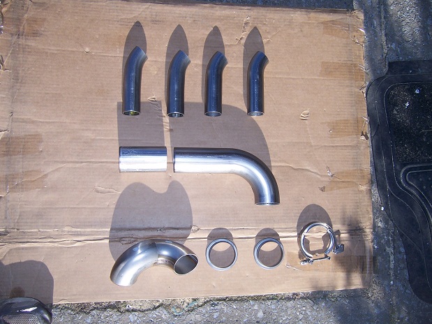
Once that was done, My piping that I need for the crossover/turbo manifold showed up!
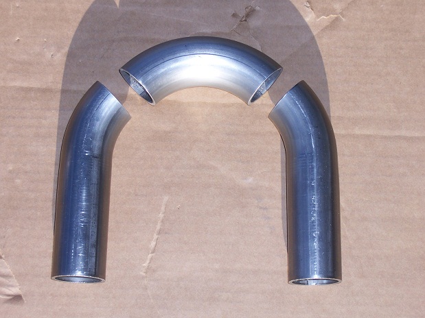
The large 90's are 2.25" 304 stainless weld joints, about 1/8" thick!
All the other parts are for the wastegate, 1.5" bend, 1.5" flex, 1.75" 90, 1.75" straight.

Preliminary layout for the wastegate

The Proposed arangement somewhat in place

With the concept for the wastegate settled, I figured it would be time to look at what I have planned for the turbo drain.
This was nice and simple, All I'm using is a 1/2" AN flare fitting on the bottom of the turbo, and a piece of 24" long 1/2" appliance gas hose. I decided this would be best because, as it is stainless, it can tolerate extreme temperatures, (that it should never encounter!) It acts as a coalescent for misting oil, and since it is thin, and has a bunch of surface area, the oil inside it will self cool. Hopefully it'll do as I think it will. It wasn't difficult to find that ideal mostly downward position for it. Don't know If I'm the first to do this, but I think its a great idea!


I just got started on building the Crossover manifold.
There is going to need to be a collector just before the turbo, where I merge both 2.25" pipes into the single 2.25" inlet of the turbo. So what I'm going to do, is to run both exhaust pipes straight to the turbo one at a time, and mark their orientation on the turbo inlet flange, then I will draw a 50/50 center line across the two orientation marks, and cut the two individual pipes on that axis. If I get it right, then they will form a perfect collector. I will also have to cut a hole in the top of the collector for the 1.75" wastegate pipe that will point straight up. I'll post pics of this process.
So far, I did some trimming the two bends that I will be using for the front exhaust bank, and got a perfect fit for them. Hopefully tomorrow I will get some welding action on these pipes. There is not going to be any flex joint on this connection, just due to space reasons. The turbo bracket itself is flexible enough to accomodate the heat expansion that will certainly occur, and there will be a flex joint on the rear bank, down pipe, and wastegate. That should be sufficient.

Thats all I got for you folks tonight, Thanks for watching!
|
|
|
|
Joseph Upson
|
FEB 13, 06:14 AM
|
|
I made my shift cable bracket at the tranny adjustable and recall some remarks in descent about doing so, I believe flexibility even where it is not foreseen is important, GM included some adjustability with the originals. Many of the F40 transmissions are very difficult to impossible to shift into the lower gears in cold weather below 60 deg and often times I've had to start the car with the tranny in gear otherwise I would have to shut the engine off to do so until the tranny gets warmed up from use.
The potential problem with that is some times impatience sets in and you can start to force the gears stressing the shift cables. Light duty cables (Advance, Autozone, etc) will not hold up and even the good ones can start to show some fatigue as mine have a little, or the bracket may have bent a little. It still shifts fine when warm but cold initial shifts sometimes fall short of being fully engaged now which I can adjust for. You may want to consider at least a custom gear shift cable thicker than what's currently available for more firmness in shifts. I know Rodney makes a good cable, I purchased mine from the Fiero store and although not the same to my knowledge, they look exactly like the ones he makes regarding quality and are much better than what the local parts stores provide. It doesn't look like you'll have much room to work in that area once it's in the car so keep that in mind.
Disregard, I see now you have a cable source should it become a problem.[This message has been edited by Joseph Upson (edited 02-13-2013).]
|
|
|
|
Joseph Upson
|
FEB 13, 06:29 AM
|
|
|
1/2" drain back from the turbo is cutting it very close, especially since it is angled which will reduce the flow rate from the turbo, you should have at least 5/8" to be on the safe side as oil comes through really quick after it heats up. If it's a ball bearing unit okay, but the coolant jacket tells me it's not. I'm speaking from having backed oil up into the turbine housing on a number of occasions. You don't want to restrict oil flow into the turbo unless you have to due to high pressure, not restrictive drain back.
|
|
|
|
Will
|
FEB 13, 09:30 AM
|
|
| quote | Originally posted by Joseph Upson:
The potential problem with that is some times impatience sets in and you can start to force the gears stressing the shift cables.
|
|
You're using two of what were originally designed as select cables, right? The cables designed to be shift cables are significantly more robust than the select cables.
| quote | Originally posted by Joseph Upson:
If it's a ball bearing unit okay, but the coolant jacket tells me it's not.
|
|
It is a ball bearing turbo. I thought that the BB center sections needed cooling jackets more than the journal bearing centers.
|
|
|
|
Will
|
FEB 13, 09:38 AM
|
|
| quote | Originally posted by Fierobsessed:
Once that was done, My piping that I need for the crossover/turbo manifold showed up!
The large 90's are 2.25" 304 stainless weld joints, about 1/8" thick!
All the other parts are for the wastegate, 1.5" bend, 1.5" flex, 1.75" 90, 1.75" straight.
|
|
Weld El's rock. It's good that you're going that thick for the hot side piping. I went with 11 ga mandrel bends for the primaries on my Northstar manifold... and it's not even turbo. A friend had a custom manifold made for his turbo MR2 Spyder a few years back using SS Weld El's.
|
|
|
|
Joseph Upson
|
FEB 13, 09:44 AM
|
|
| quote | Originally posted by Will:
It is a ball bearing turbo. I thought that the BB center sections needed cooling jackets more than the journal bearing centers.
|
|
I'll have to check into the cables again as the thicker OE cables I had could not be used due to the larger cup size.
I remember reading differently about the ball bearing turbos due to reduced friction which also permits much less oil flow. I've seen them with both though and didn't see where he mentioned it was BB.
|
|
|
|
Fierobsessed
|
FEB 13, 11:59 AM
|
|
The oil inlet on this turbo has an oriface restrictor that is only .035" in diameter, the oil flow required is very low on this turbo. The drain hole on the bottom of the turbo is actually pretty tiny too, I think the 1/2" drain line isn't going to give me any grief. If it does, I'll source out some 5/8" line.
The one thing that sucks about the crossover manifold, is that although I have the 11ga weld el's, I still have to run the thin material at the manifolds, as they flare out on the manifold. It will be the most likely to crack where the two thicknesses are welded together. I wanted to use the weld el's due to there fairly tight radii that they have. Those buggers eat sawzall blades though!
|
|
|
|
Joseph Upson
|
FEB 13, 12:38 PM
|
|
|
I use 18 TPI blades and a cheap lubricant to keep the blade cool. [This message has been edited by Joseph Upson (edited 02-13-2013).]
|
|
|
|
Fierobsessed
|
FEB 14, 06:31 AM
|
|
Some more progress!
I did some welding on the front bank crossover tube, I first started by putting the pipes in place and making a couple of alignment marks with a sharpie, then I remove the pipes and clamped the two together on my work table do a couple of light tack welds, and then do the full weld once I removed all the clamps. Here it is just before I tack welded it.

Traditionally, when you are tig welding stainless pipes together, you have to do what is known as a back purge. Essentially, you fill and run some of your shielding gas (argon) into the inside of the pipe, so that the oxygen in the atmosphere doesn't react with the metal on the inside of the pipe opposite the weld zone. This wastes a whole lot of shielding gas.
A friend of mine turned me on to this product called Solar Flux "type B".

This stuff is basically a super fine powder, that when mixed with methyl alcohol (I use HEET, from autozone) forms a paste. I apply the paste to the inside of the two pieces I'm about to tig together, then weld away. The heat of the weld causes the Solar Flux to turn into a hard glass like shell that insulates the back of the weld joint from oxygen, saving me a bunch of argon. Pretty neat product!
However, I've also read that it should not be used in a turbo manifold as the glass like substance it leaves behind could flake off and damage the turbo's turbine blades. But, I use the sand blaster on the inside of the joints, removing any and all traces of the solar flux. So this process leaves pretty clean welds, and no residue.
I am, by no means an expert welder. I am far too under practiced to be considered anything other then amature. But still, I enjoy the challenges of fabrication. So take any welding advice I give with a grain of aluminum oxide.
After that weld was done, I put the pipe inplace and had to do a couple of in situ tack welds to join the new pipe to the flange piece mounted to the manifold. Here I am about to do just that.

After the tack weld, final weld and some more sand blasting


I had a little extra time this morning and managed to get started on the rear bank tube. I welded the two joints as needed, and started fitting them into place.

The next challenge, now that I have the two pipes that need to join together at the turbo flange, I need to figure out exactly where to cut them to form a nice clean collector. This is actually pretty tough to do. I'm going to get my hands on some form of laser to draw out the lines on the pipes. I drew out the 2 orientation marks on each of the two pipes, then transferred the 4 marks to the turbo flange. Then I drew my 50/50 mark to indicate the spot where the seam will intersect the flange. This was a good starting place for marking out the collector Y. I'll get that going tomorrow hopefully.
Things are moving right along, and with that, the end of page 1.
|
|
|
|