
 
     |
| Trinten's SBC/F23 build - The work has begun! (Page 55/76) |

|
Steel
|
MAY 05, 09:33 PM
|
|
|
I can now see all the pictures~ Great work on the sunroof, I really need to address mine as well.
|
|
|
|
Trinten
|
MAY 09, 02:55 PM
|
|
So planning ahead to some gauges...
I've got the turbo Sunbird cluster, there are two users that I've found that have installed this, one (reportedly) is Tom. The other is FieroGuy123. I've reached out to the latter to see if he did a build thread on how he installed it.
Now this means that when I put in my Amida interior, I'll need to create a new bezel. Not worried about that.
Since the Sunbird cluster has voltage and oil pressure (and boost), it leaves open the spots where the GT Pod gauges go.
In the short term, I'm going to mess around with an extra GT Pod I have. I took measurements of the bezel opening (roughly 3.225" x 1.724" viewable), and measurements of the space the gauges take up behind the bezel in the pot housing.
I'm likely going to put in a Transmission temp readout, and for the other space, a wideband sensor readout.
I looked at Speedhut ditigal gauges for transmission temps, and I bought one, unfortunately now(March 2023) the link to it seems to be dead. The part number for it - GL-DG-TRNS-01 doesn't come up on their site.
The measurements look like I can take off the outer bezel, maybe modify the housing a bit, but should be able to center the actual display part in the center of the GT Pod!
I hope.
So ordering that one today to experiment with. If it works out, I'll make my final choice on the other one, find one the same size, and do the same thing.
Since I have leather wrapped A and B pillars, I don't want to put the A-pillar gauge pods on it. Amida's center console section also has a 'blank space' with a cover panel, We're going to mount some USB ports there (one to go to the FAST, one for charging). In the future I'll have to take some measurements of the spacing behind it, maybe I can squeeze another gauge back there, opening up the cover panel for it's face as well.
[This message has been edited by Trinten (edited 03-26-2023).]
|
|
|
|
Trinten
|
MAY 27, 07:51 PM
|
|
Super quick up date for some continuity because I haven't gotten the pics off and fixed up yet.
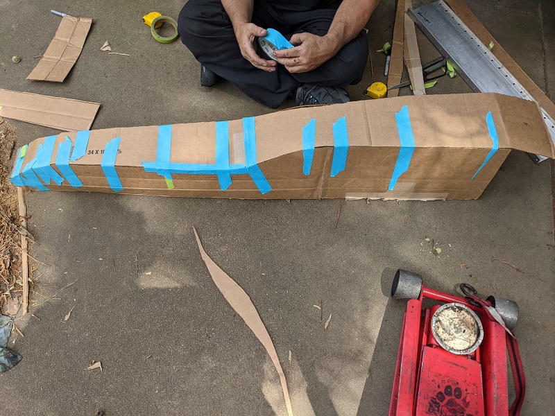
Mike decided instead of trying to edit the fuel tank drawings that are floating around, he was going to come up with his own and maximize our available space. When he got under the car, he says "I see why FieroGuru cut a tunnel out of a Fiero. This shape is ridiculous."
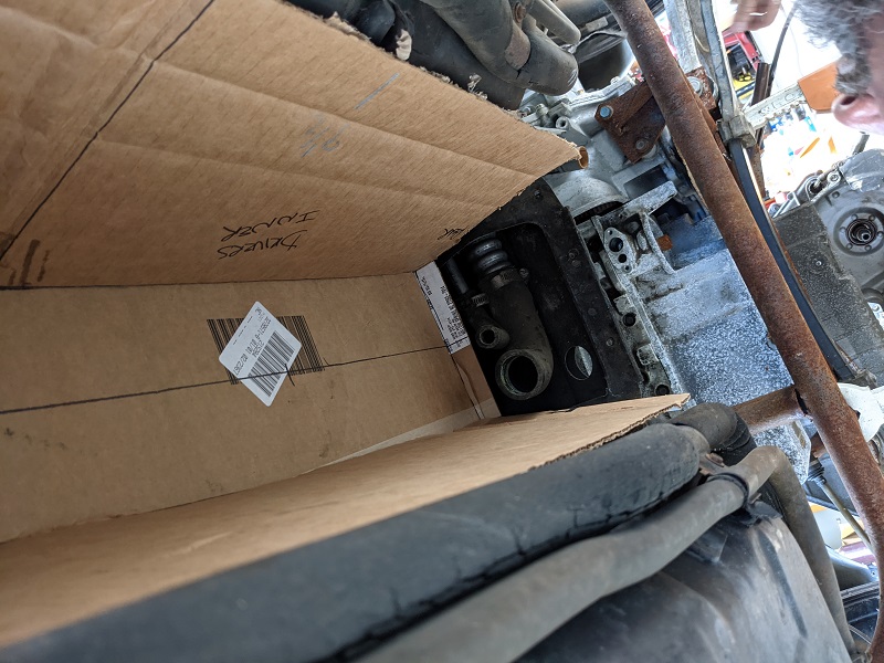
He then started working on a mock-up out of cardboard, hugging the tunnel as much as possible and maximizing our space at the end. He had a concern about how far back the tank could go, namely in order for us to have room to get the hose clamps on. I recommended cutting up that metal thing at the back of the tunnel, but he didn't want to do that (more on that in a minute). So he goes "Might have to cut it back to closer to stock tank length."
I say "What about quick disconnects." he pauses (and some other guys were hanging out), and says to them "Watch this. I've learned not to say something doesn't exist with this guy around."
He gets under the car with a tape measure. "Okay, if you can find stainless steel quick disconnects with an OD of half-inch and 1.5", we can investigate that.
Took me about five minutes to find them from about three different sources. So I ordered a few for us to play with. 
He has the mockup at a big metal work and fabrication shop that he does business with, asked them to make a rough-up of his mockup, since it'll likely get beat up, bent, cut, etc. Then we'll deliver that to have the final version made.
His reason for wanting to leave the tunnel and 'hose holder' in place? Because he reminded me I wanted to investigate how much it'll be to have these tanks made and where the price breaks would be, both in stainless and aluminum.
When I get the prices, I'll post them up if anyone is interested! I know folks like Rodney had investigated it but had to walk away. Hopefully I can provide a 'small batch' channel for this. I'm sure shipping is going to be expensive.
The metal shop anticipates having the alpha tank back to Mike sometime next week. So hopefully about mid june we'll have the modified/tweaked alpha back to them to create the beta, and then the production unit!
|
|
|
|
Trinten
|
JUN 06, 06:06 PM
|
|
Gas Tank mockup, wire order and coolers
A little update and pictures!
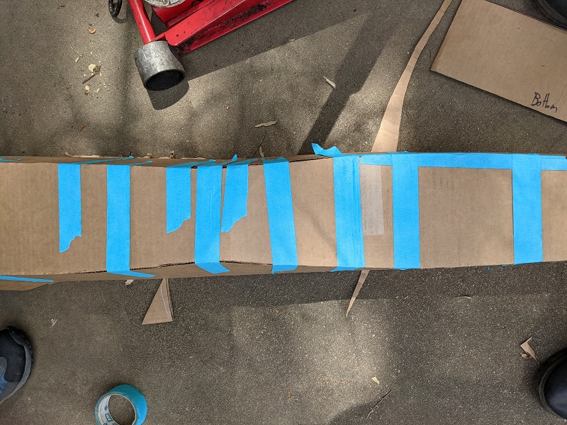
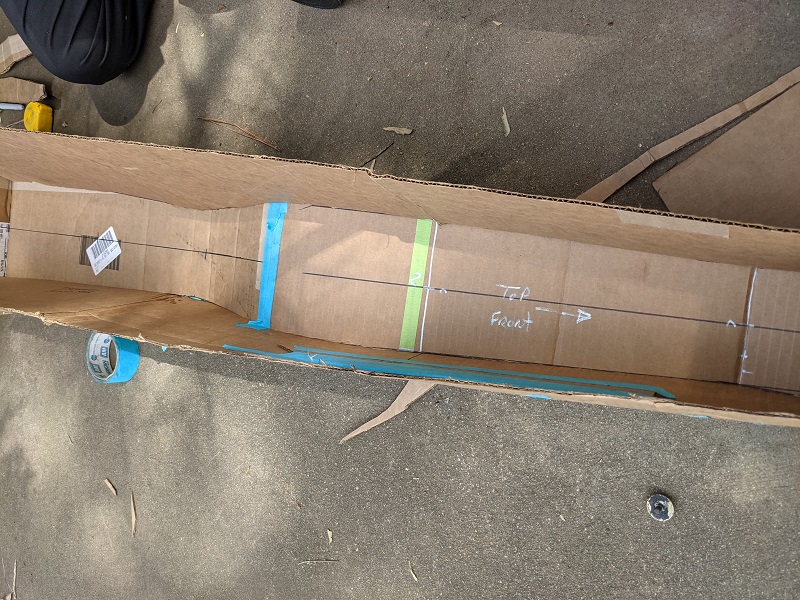
First up is some of the pictures I took when Mike was measuring, cutting, and test fitting for his gas tank mockup.
We're still thinking about hookups to the two stock lines (filler neck and expansion tank). He's trying to maximize all the space he can, without cutting up that metal piece the two hoses come though. I've suggested different quick disconnect and push to connect solutions.
The hard part is finding a solution that will work with OEM fiero stuff without taking up the room to get a hand/pliers in there to put on hose clamps. The lines going from the tank to the fuel pump and so on will be much easier.
Still waiting for the metal shop to get the pieces back to Mike for next phase of mockups. This was expected, Mike did tell them it was a low priority job.
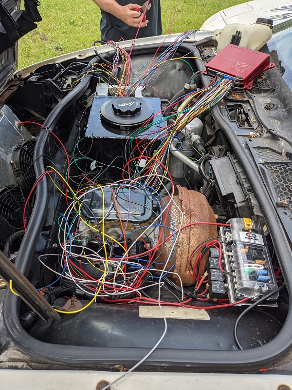
So this past weekend the focus was on wiring! Lots... and lots of wiring.
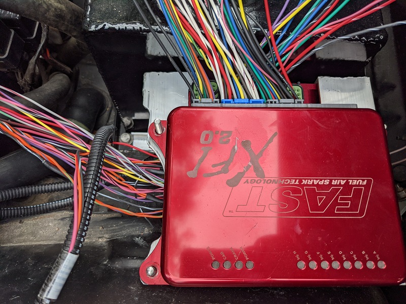
Because I went with FAST, and we were putting the modules up front, we knew we'd need to cut the wires and extend the harnesses. To make sure all the wiring was the same for any future troubleshooting, I called up FAST and asked if I could buy wire in the appropriate colors... they said no.
Well, if they don't want my money, someone else would! I went through the XFI and XIM wiring diagrams for LS, and wrote down every striped color combo... and found a great company to work with. Adiwire.com was happy to fill the order, and though the minimum was 500' per color, the cost per foot was about half if I would have been able to find and buy that much in the smaller spools.
You'll see I had a few small spools of solid color. 20Ga SXL copper strand wire. I foolishly underestimated how much wire we'd need, so I'll be ordering spools of the solid colors from ADI tomorrow.
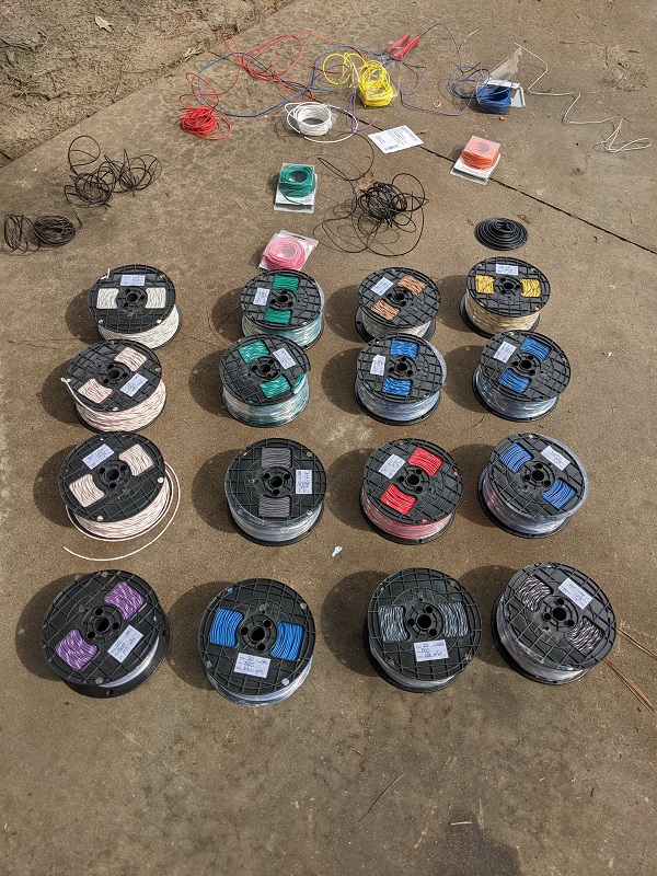
My collection of wiring, so far!
Yes, this looks crazy. But Mike actually laid it all out that way to make it easy to group it.
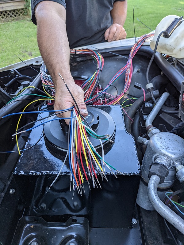
After finishing making the bundles.
Not quite done (need more solid color wire), but mostly done with the wiring up front.
To protect all of it, I got some high quality fiberglass high-temp loom from a company called Insultherm. I got it in three different sizes. It's nice, can be cut with scissors, flexible, and highly abrasion resistent.
I have other stuff for the really high temp areas in the engine compartment.
The wiring cout up front does mean we won't be able to use just the one Deustch connector we got, I'll need to get a second one. The space Mike was planning for it will still work.
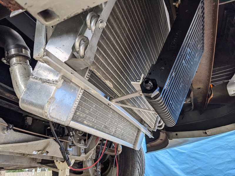
A shot of the Derale transmission cooler is mounted!
I got the wrong fittings though, so need to fix that.
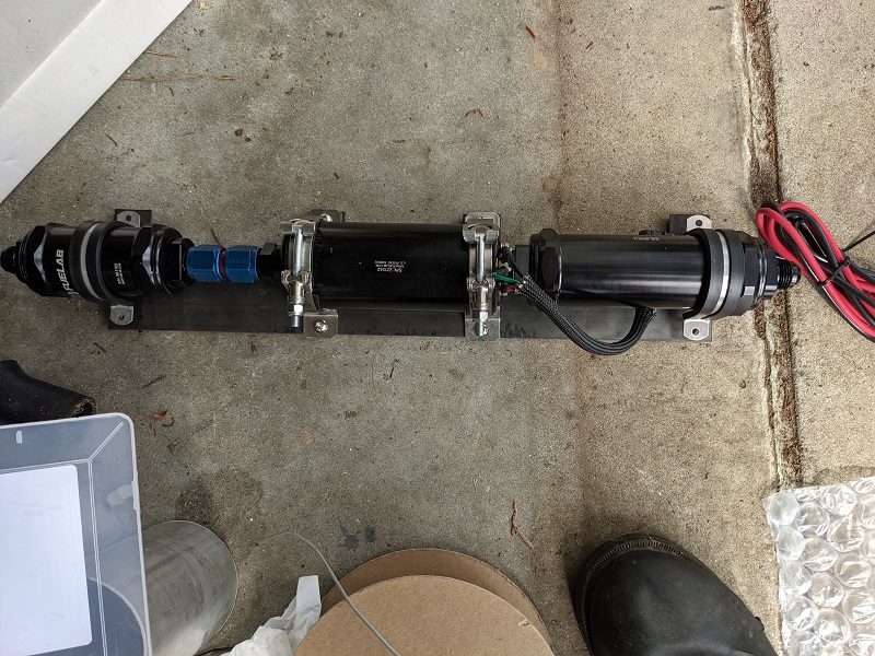
And lastly, the mounted test setup for the pre- and post- pump fuel filters, and the pump itself. Once everything is mounted and finalized, the mounting will go off for powdercoating.
[This message has been edited by Trinten (edited 03-26-2023).]
|
|
|
|
Trinten
|
JUL 22, 06:54 PM
|
|
Hey everyone,
So not a huge update, just some little stuff, some of it starting from late June (weekend before Carlisle).
Mike and I got the cradle and drive train out, and he had split them apart. He made some final adjustments on the cradle and did most of the primary welding, compared to the spot welds that had been in place. It was smart that he did that, he did discover he had to shift the drivetrain back and up a little (less than an inch in both directions). And while it was out we swapped over to the Moroso Oil pan (and modified pickup tube) and installed the starter. Also have a pic of the beta-assembly for the fuel system mounted to the cradle.
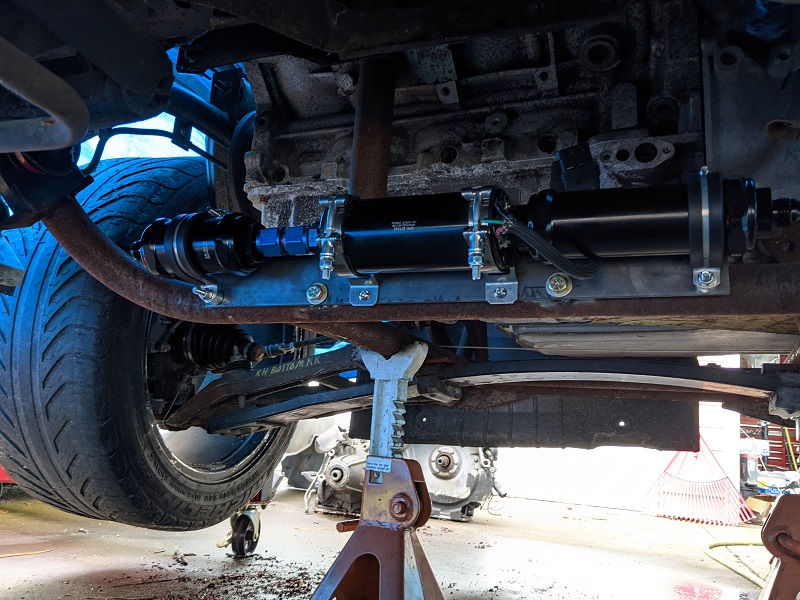
The aforementioned fueling setup. The pre-pump filter, pump, and post-pump filter. All FueLabs stuff. They have great pre-sales support, talked with them about power goals, fuel type (flex fuel) etc, and they were great about giving me options and the pros/cons between them.
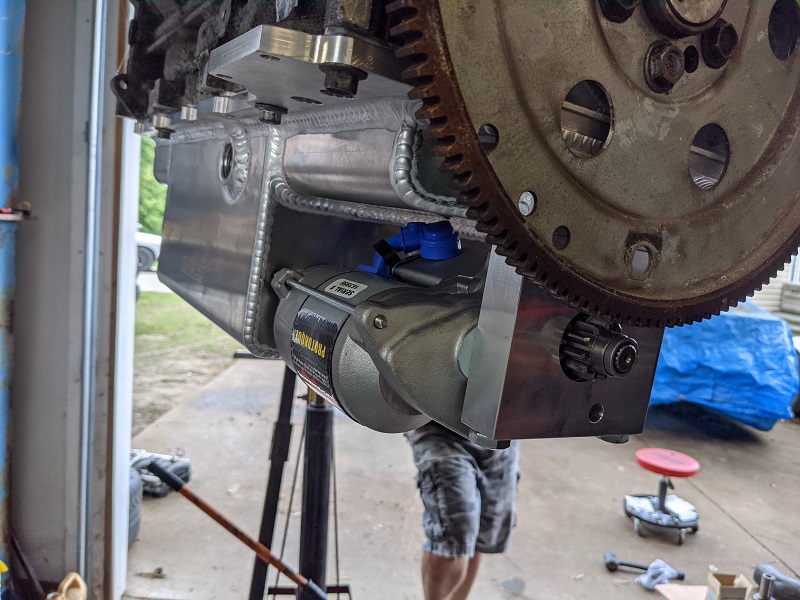
This is the LS4 / 4T80 Oil pan and it's accompanying CVR starter. It's a nice piece!
I also worked with ADIWire to get a bunch of solid colors. Realized it was going to be way more cost effective to do that than keep buying smaller rolls. Plus, when it's a solid color, they don't have a minimum-length like they do with spiral-colored wire, just the less you by it changes your cost per foot. I got enough of each of the solid colors that my cost per foot didn't increase, and because there was no spiraling involved, there was no setup fee... so it was VERY affordable.
There's been more work (and pictures) since these were taken, of course. But not enough for it all to make sense in context, and I'd rather wait and get more pictures to do a more coherent story. The last few weekends Mike has been working on exhaust stuff, getting more of it mocked up, and working on the intake plumbing.
We did realize there simply wasn't enough room to go with our original 'packaging' idea, so we're going to flip the intake back around to face the passenger side. Which also means we'll need to take the torsion rods off, as they won't clear the throttle body. So that's on the agenda soon. Also means Mike needs to cook up a mounting point for the gas-strut that I kept from my Rodney Dickman setup from the last Fiero. Or another mounting solution and just need to find a gas-strut that's the right length.
We did do some of the fabrication work that I'm really excited to show off once it's finished (want the rest of the pics when it's set up for context and a clear view). I think it's going to look pretty cool, and be functional!!
[This message has been edited by Trinten (edited 03-26-2023).]
|
|
|
|
Will
|
JUL 25, 07:54 PM
|
|
Does the Moroso pan have that ridiculous protruding drain plug that they showed on the prototype?
If Mike is cutting & welding, he could fix that...
|
|
|
|
Trinten
|
JUL 25, 08:08 PM
|
|
Intercooler intstallation
Okay so Mike did some cool stuff this weekend.
I mentioned before that trying to package all of the plumbing with the intake facing the transmission side was getting tight and while possible, wasn't ideal. So the intake was going to be spun around. This still left having to modify the intake plans.
Since the intercooler was already going to occupy the trunk, Mike decided to route the intake tube through there, too.
Originally he was going to use some of the oval tube I bought, and tuck it in right below that 'bracing' point in the trunk. However making fittings to go from round to oval at both ends was going to take up more room and diminish the advantage. So he just used regular 3" tubing.
Onto the pictures!
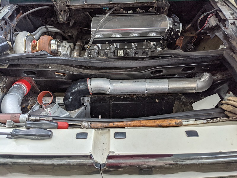
As always, Mike is methodical and likes to make fittings as clean as possible. He also wanted to make as much of the 'run' level as possible, instead of being at an 'easy way out' angle. Everything was tacked into place. Once it's all welded up, it'll be going off to the powder coaters.
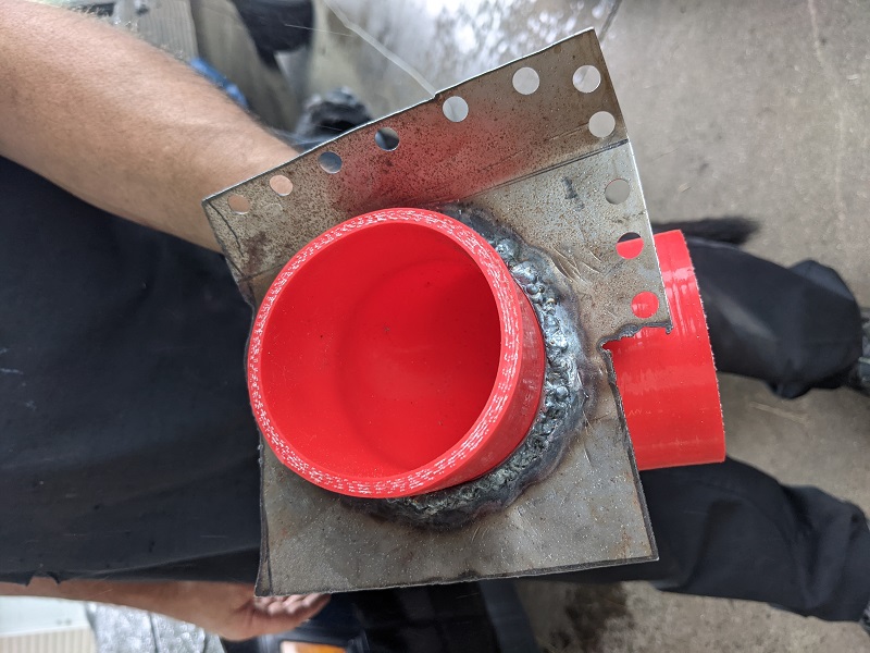
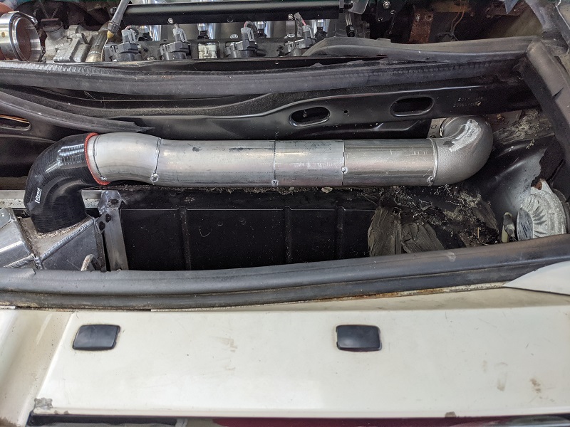
Mike cut out a place following the existing seems in the car to make room for the tube and plate to pass through. On one side, he used 1/8" wire, wrapping it around a metal 3" tube to form a ring, and then welded that onto the plate he formed. He made punches to create spot weld points and final welding, which we can then grind smooth and hit with self-etching primer.
This method worked out great, with the silicone elbow fed through, it was very snug, we can feel the ring pressing slightly all the way around, making it water tight.
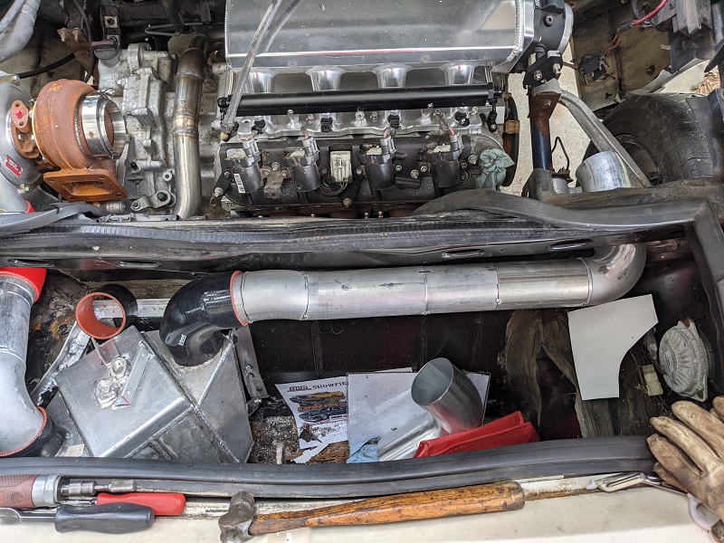
We used silicone hose in two places on the driver side, to be able to get the portion of tube off easily, in case we ever need to remove the intercooler. With the length of pipe going to the passenger side, the panel on that side has been stepped and formed flush to the trunk and will be bolted into place. We'll put a little sealant of some kind around there.
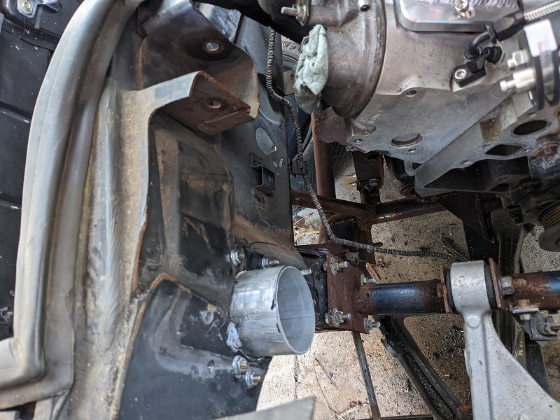
Here's a picture of the passenger side pass through, still not 'finished'.
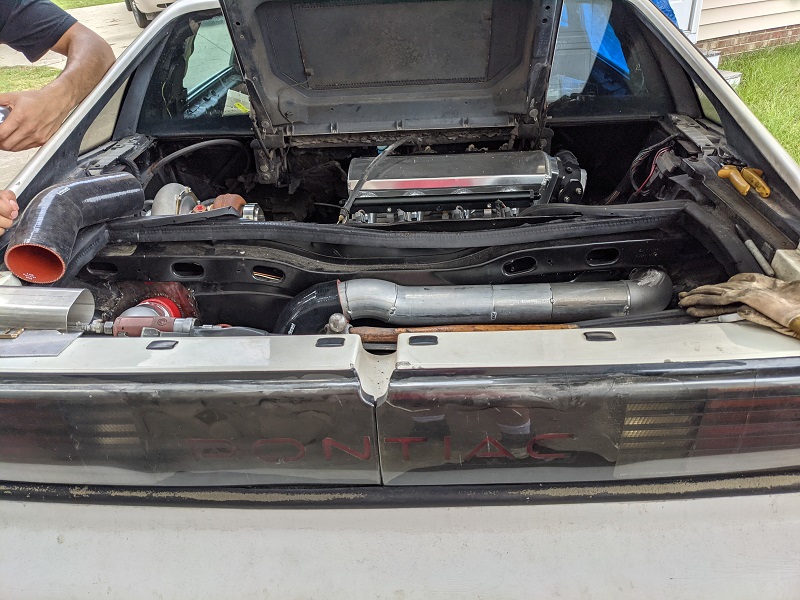
Here's a view from a little further back. The intake is not bolted down yet, since we haven't removed the torsion bar or setup for the gas strut. So right now, we're just turning the intake around each time.
A little more of a close up. Yes, this does block the current placement of the trunk light. Mike suggested we get a LED strip and mount it on the rear passenger side of the trunk (to the right of the trunk catch, and relocate the wiring. So if anyone has any suggestions for a low profile COB style LED strip that would be good for lighting up a trunk and be easy to mount (probably bolted into place instead of just sheet metal screws), I'd appreciate it!
[This message has been edited by Trinten (edited 03-26-2023).]
|
|
|
|
Trinten
|
JUL 25, 08:11 PM
|
|
| quote | Originally posted by Will:
Does the Moroso pan have that ridiculous protruding drain plug that they showed on the prototype?
If Mike is cutting & welding, he could fix that... |
|
You know... I don't remember off the top of my head. I looked through the pics I snapped with the oil pan and I didn't capture it. I know when we looked it over we didn't have any major issues with it. I'll check it out when I'm out there next Saturday!
|
|
|
|
Will
|
JUL 26, 02:23 PM
|
|
| quote | Originally posted by Trinten:
Here's a picture of the passenger side pass through, still not 'finished'.
|
|
What's the structural concept you're working up to here? I sure hope someone is planning to put frame rails back into this thing...
|
|
|
|
Trinten
|
JUL 26, 03:26 PM
|
|
It might not be clear in that picture, there is a section earlier in the thread that talks about that. In hindsight of those posts, I realized I never did a 'here is the near-final setup'.
That chrome moly tube you see holding the upper a-arm IS the frame rail. The 4130 we used has a wall thickness designed for structural support. It's the same stuff he's used to build tubular chassis'. It will remain a bolted in piece, which will allow for most major maintenance items without having to drop the drive train. When it does need to be dropped, that rail-segment can be removed to make it easier to slide the drivetrain out the side, which has a lower height requirement that trying to slide it out the back (and less complications).
If you mean the additional stiffness that the strut towers provided to hold the trunk up, I can't say for sure what Mike has in mind. The cleanup and any necessary reinforcement of that part hasn't been planned out yet. Mike wanted to work from the 'inside out', where possible, to make sure we didn't box ourselves in (literally) with anything that needed to be done for the drivetrain.
One of the things I've mentioned to Mike, to make it even easier to get the drivetrain out when needed, was to rig up a rolling 'skid' with pockets in the right place for the cradle to rest in and keep everything stable while pushing/pulling the setup.
|
|
|
|