|
| LS4 / F40 swap - fieroguru (Page 48/216) |

|
fieroguru
|
AUG 29, 09:05 PM
|
|
| quote | Originally posted by Bloozberry:
Good to see you're back at it.  The same two or three threads have dominated the top of the CZ long enough! The same two or three threads have dominated the top of the CZ long enough!  |
|
Yeah, I am glad to be making progress again!
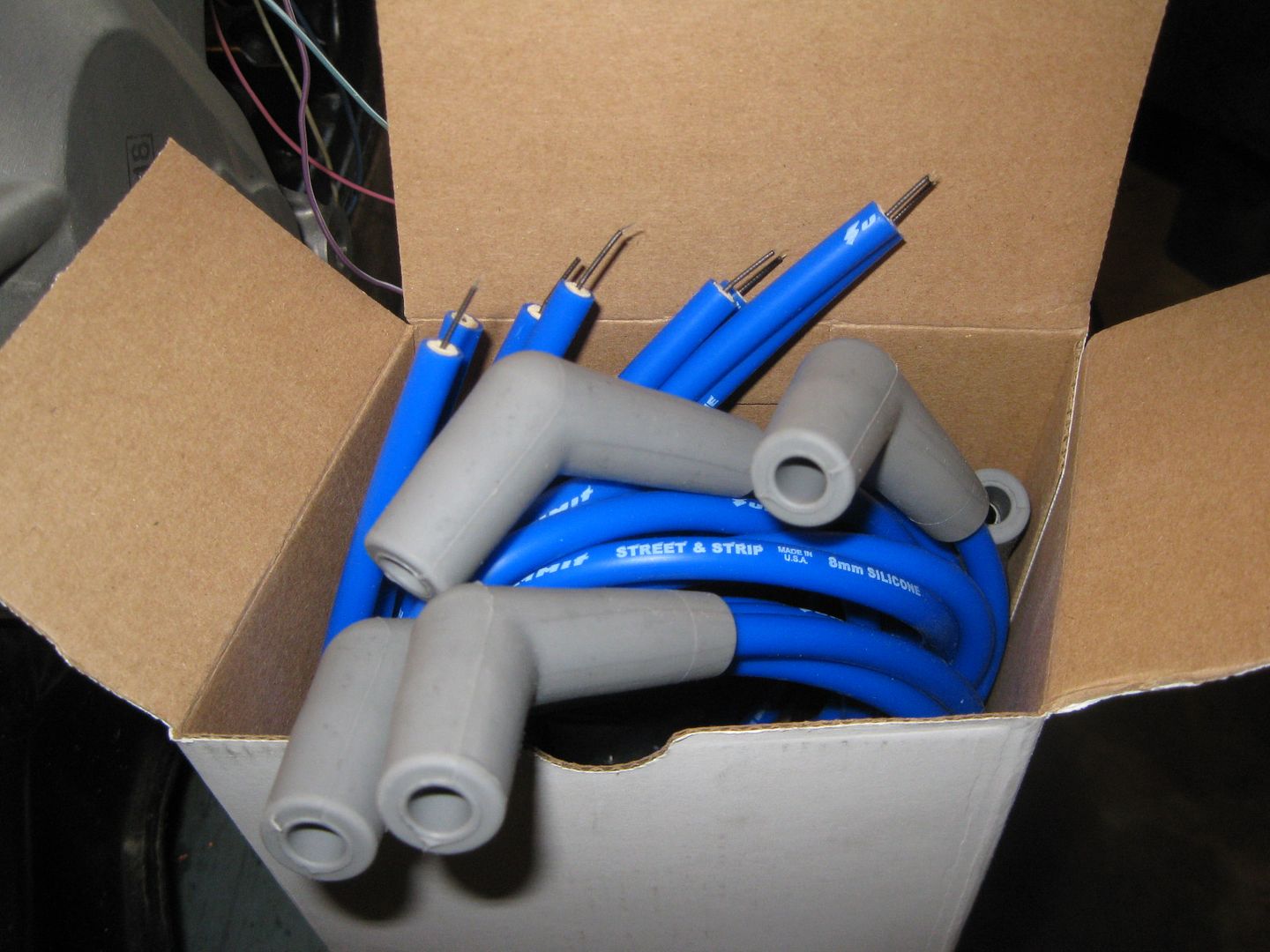
Tonight I was late getting home, but had several parts waiting for me:
|
|
|
|
fieroguru
|
AUG 30, 08:27 PM
|
|
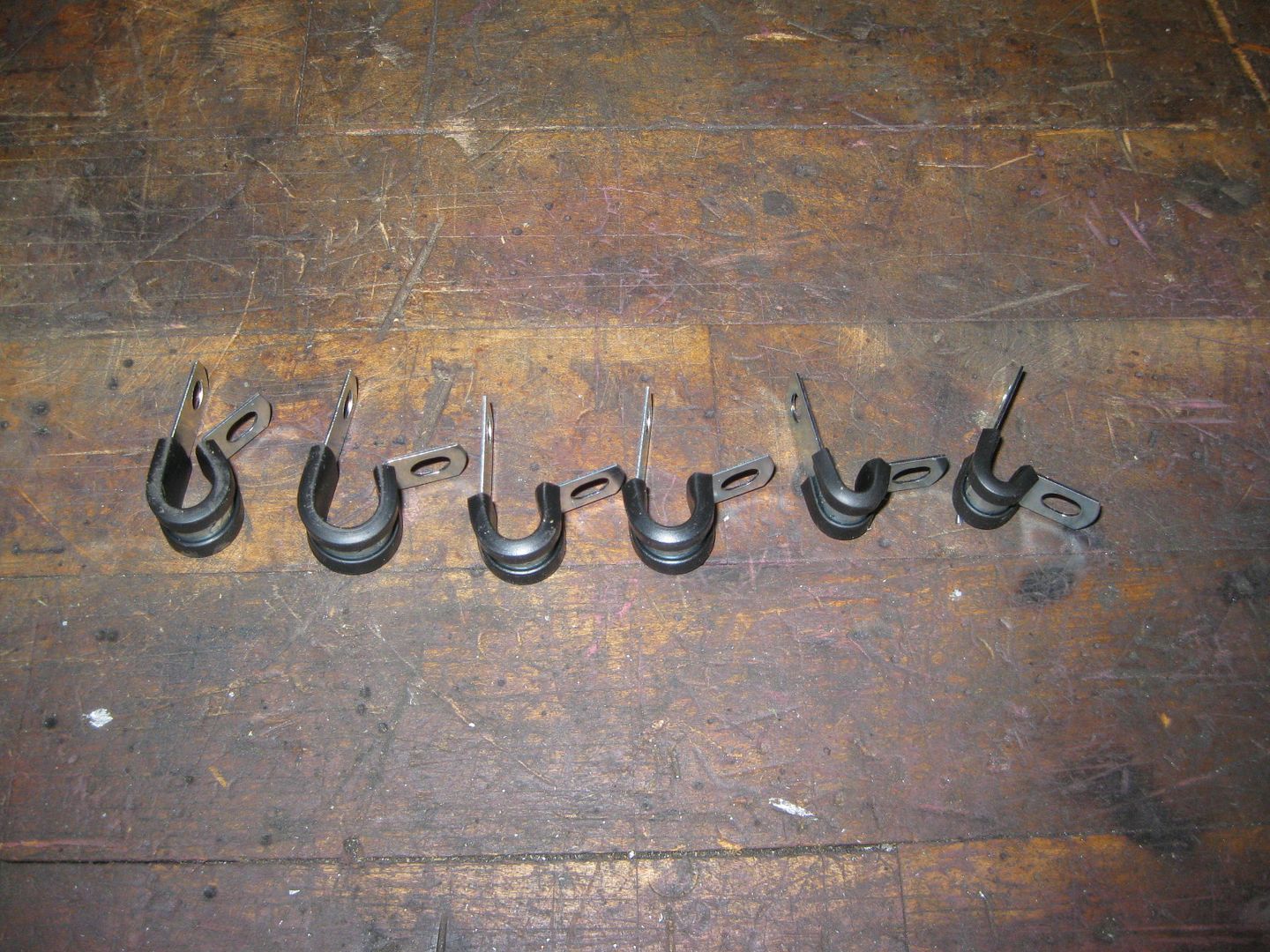
More goodies showed up today:
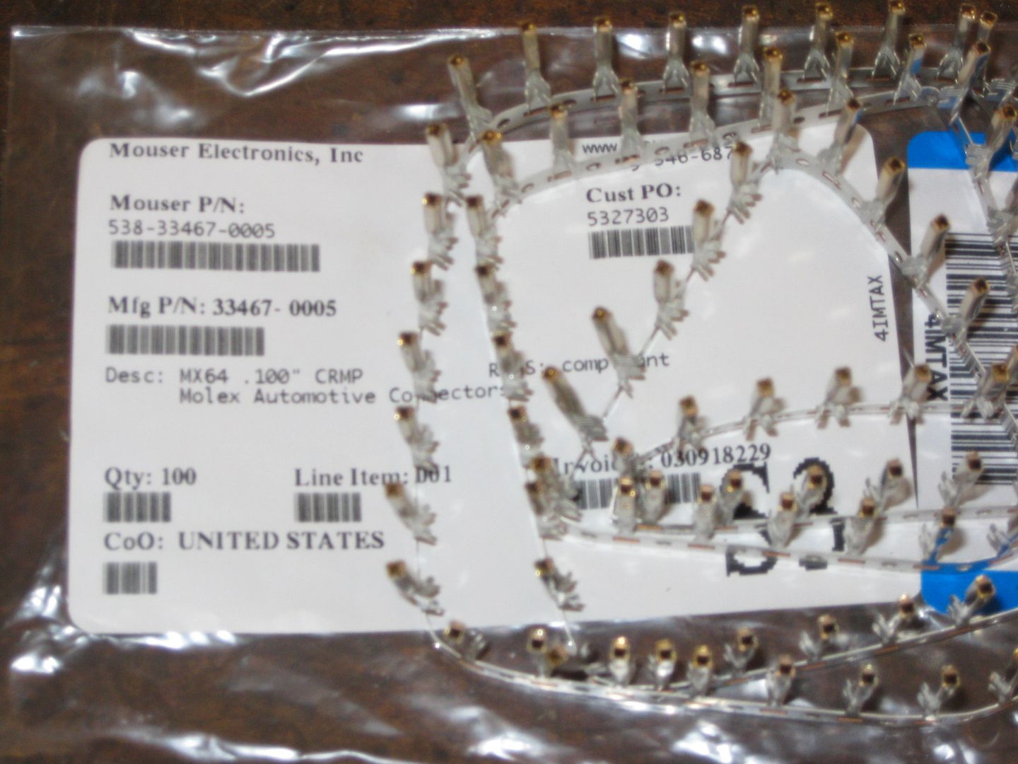
For repining the harness at the ecm:
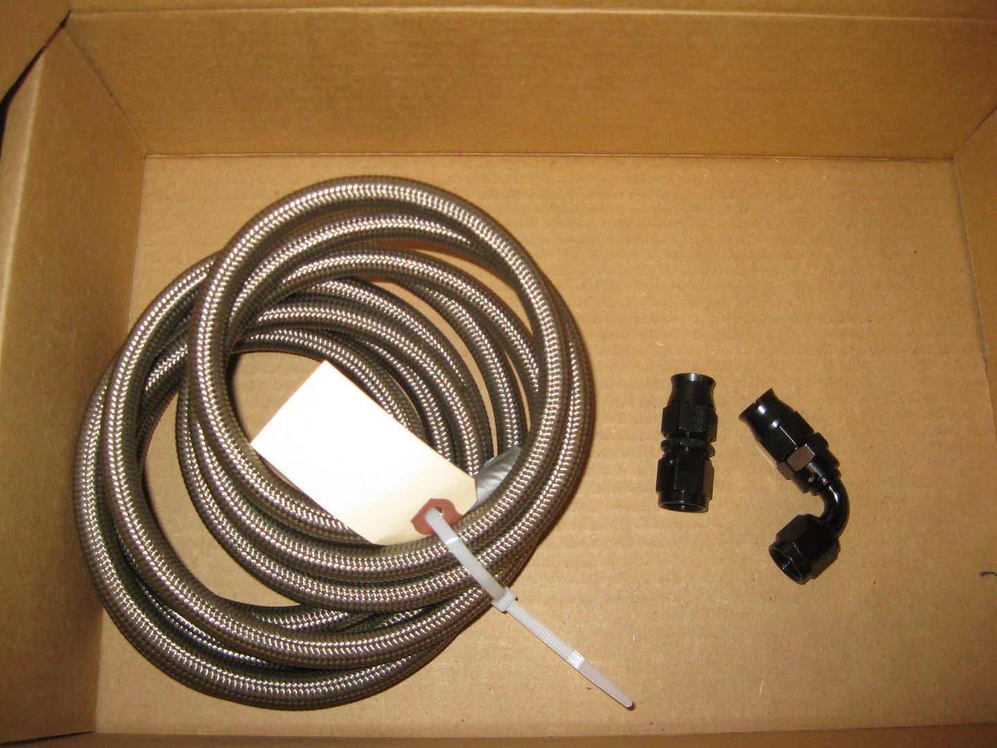
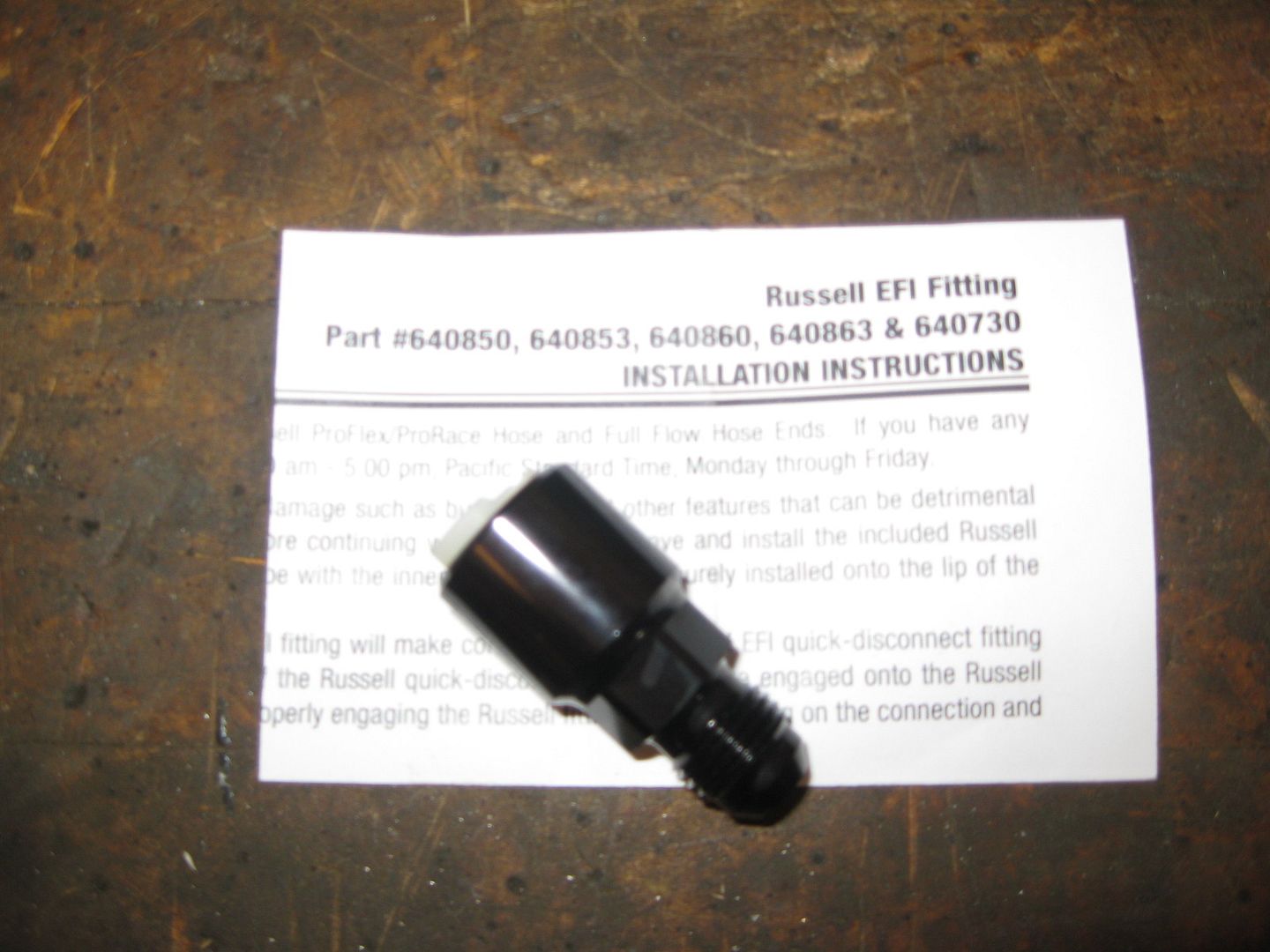
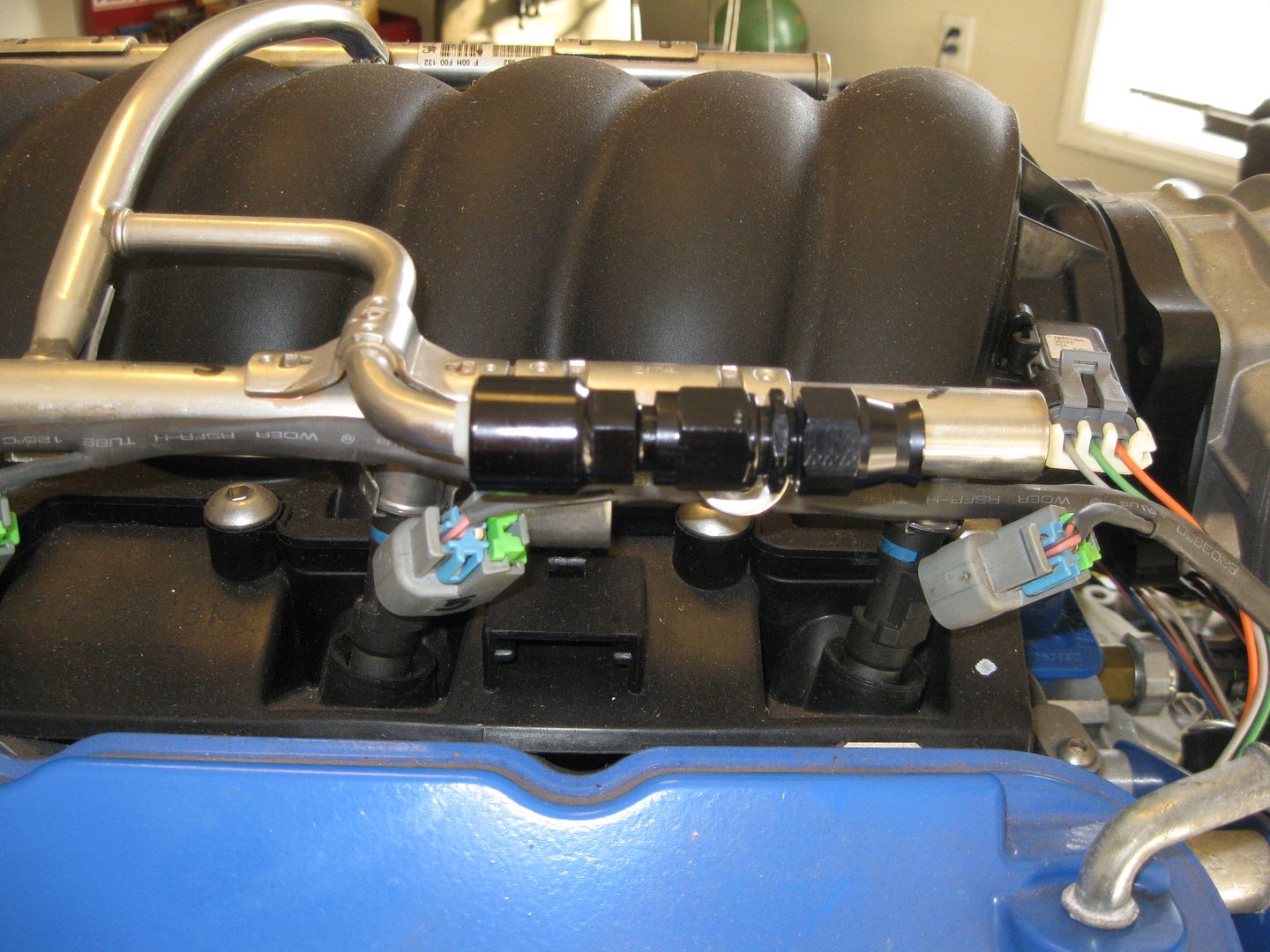
Connection at the fuel rail - GM quick disconnect to -6 AN (the 2nd picture also shows the -6 AN hose end installed):
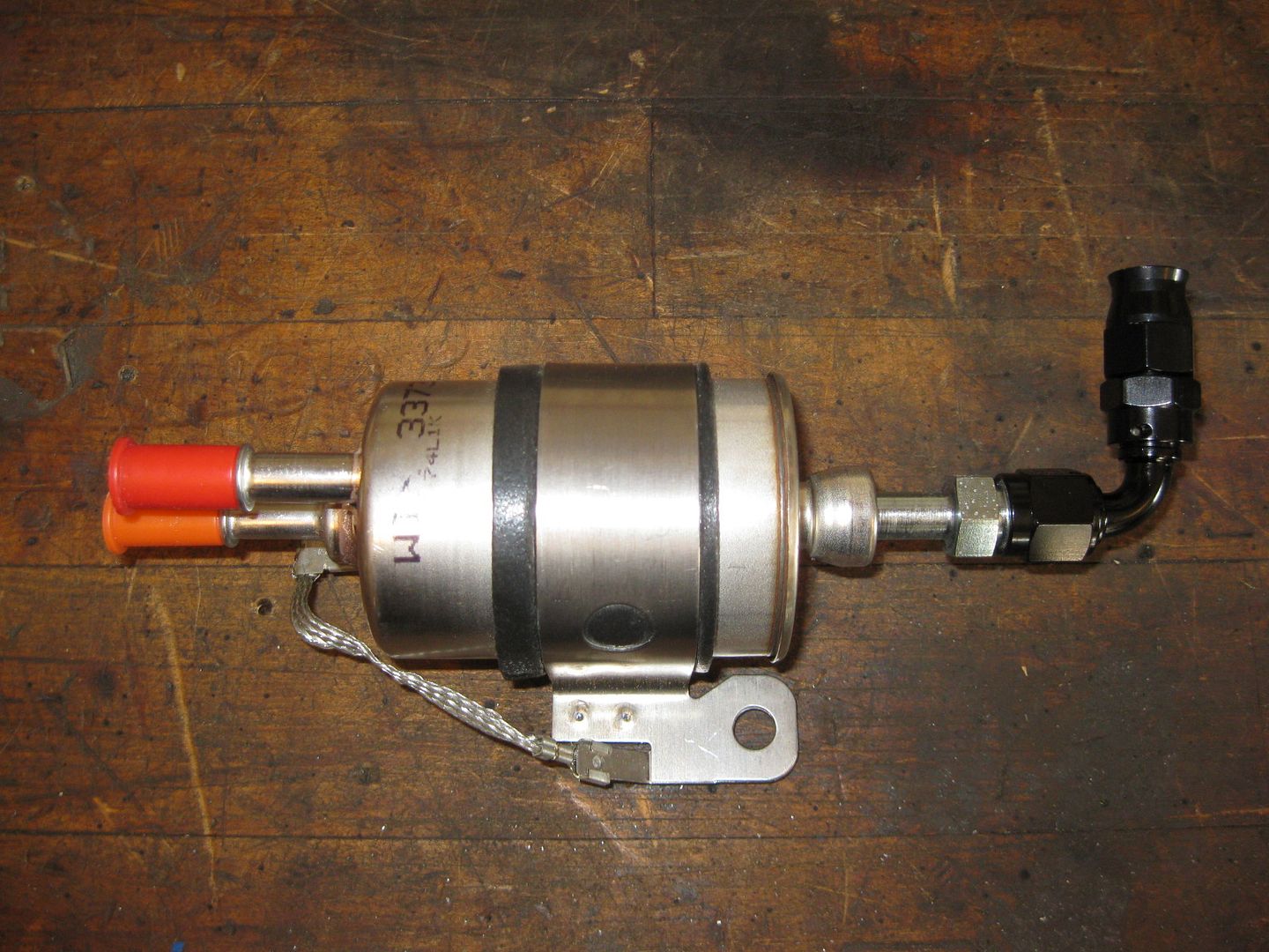
Connection to the LS2 Vette fuel pressure regulator - GM quick disconnect to -6 AN (the 2nd picture alsp shows the -6 AN 90 hose fitting and the LS2 Vette fuel filter/regulator):

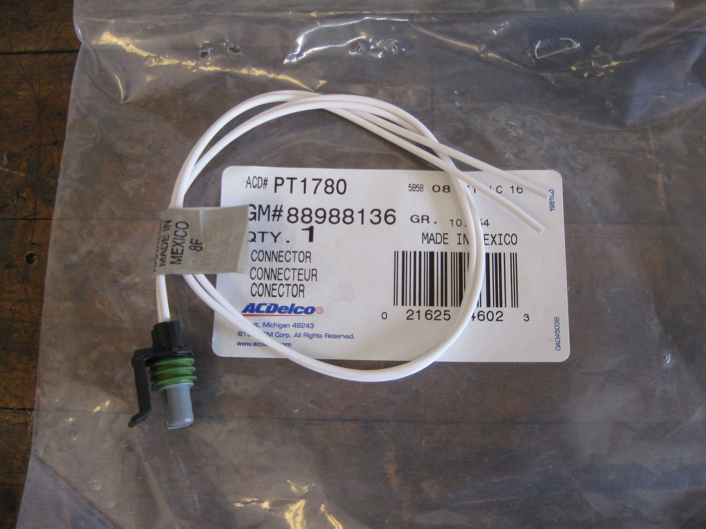
Pigtail for the reverse light switch on the F40 (spendy little thing at $40+):
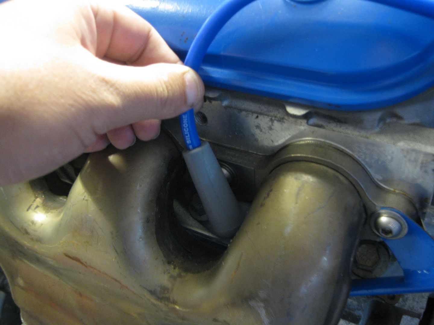
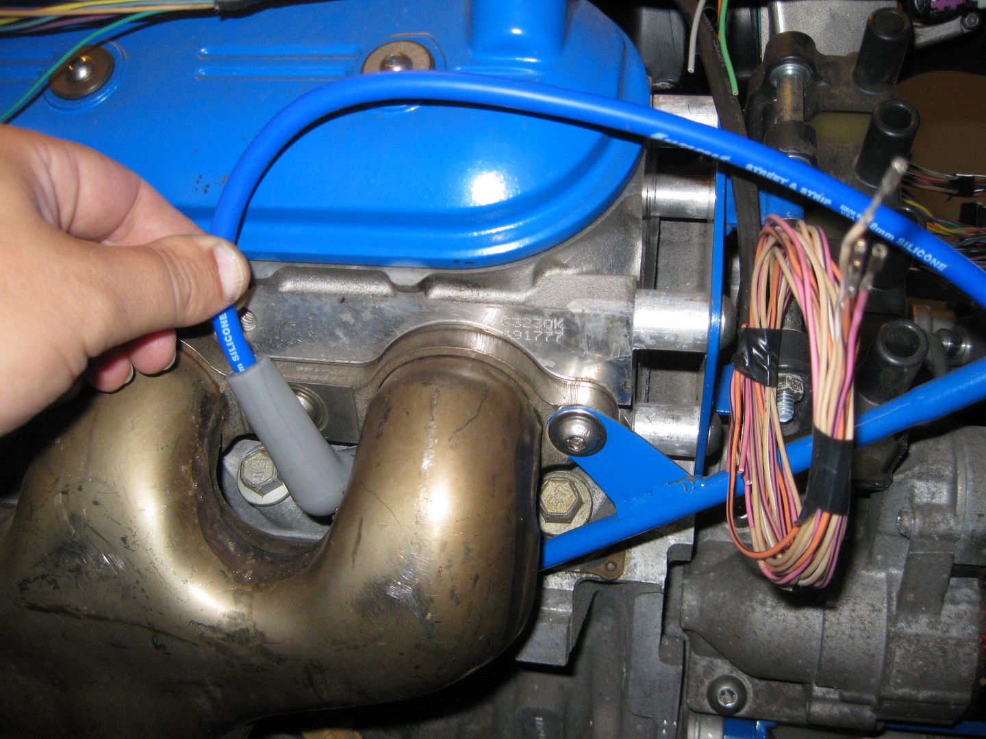
Then I started to play with the AC hose connection at the compressor. I knew it wouldn't clear the exhaust in stock form, but suspected that with some gentle massaging I could make it clear:
Before:
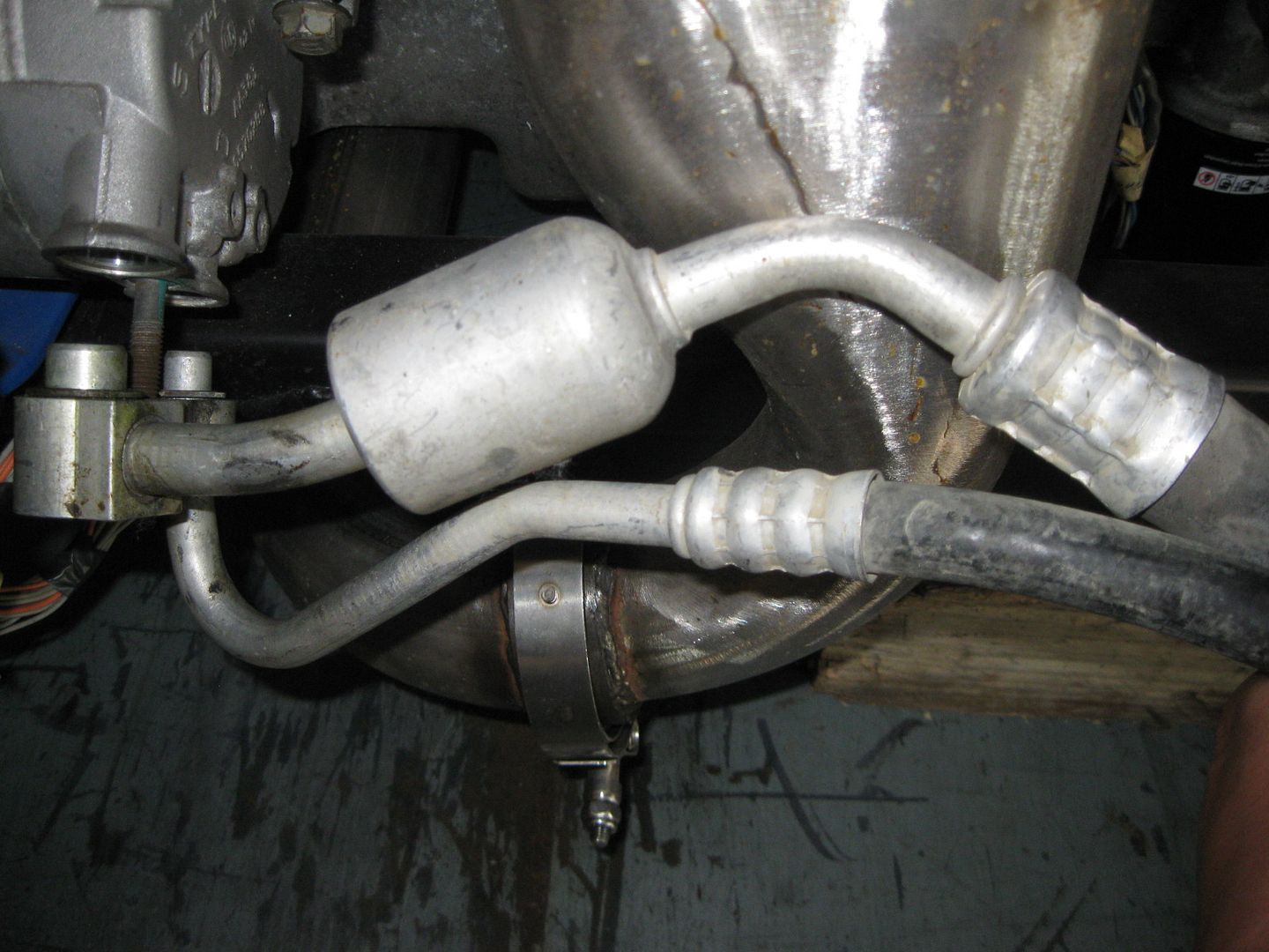
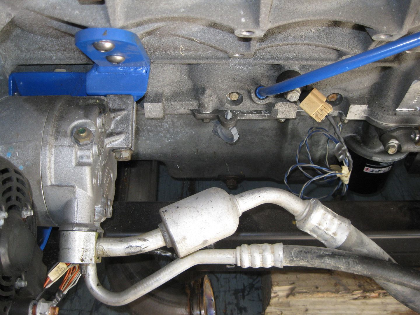
After:
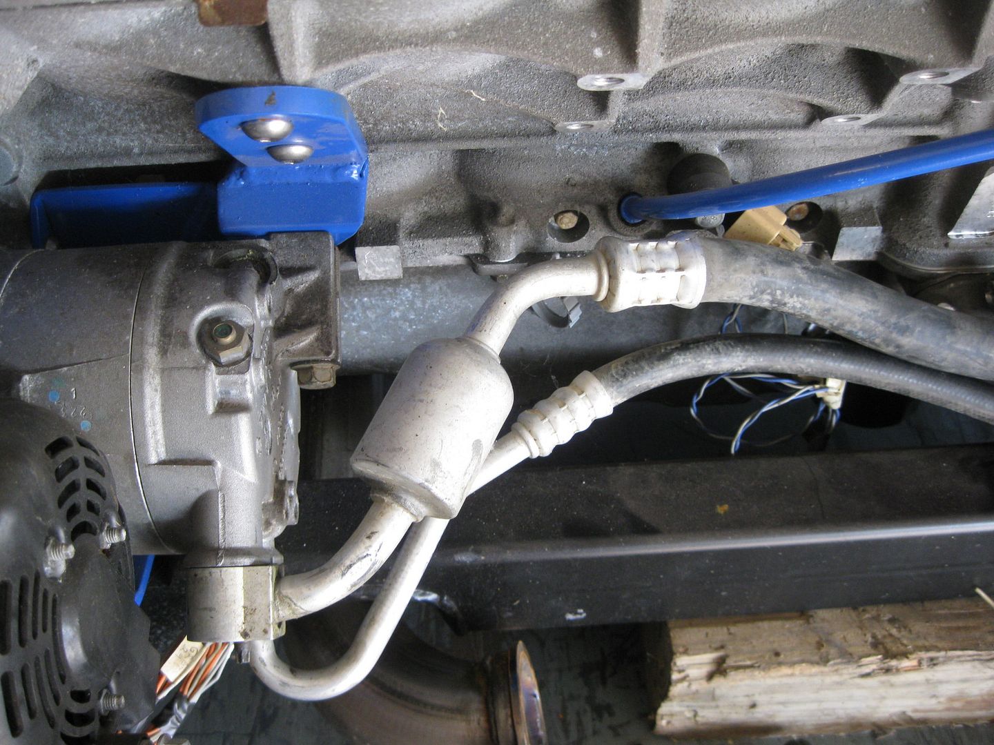
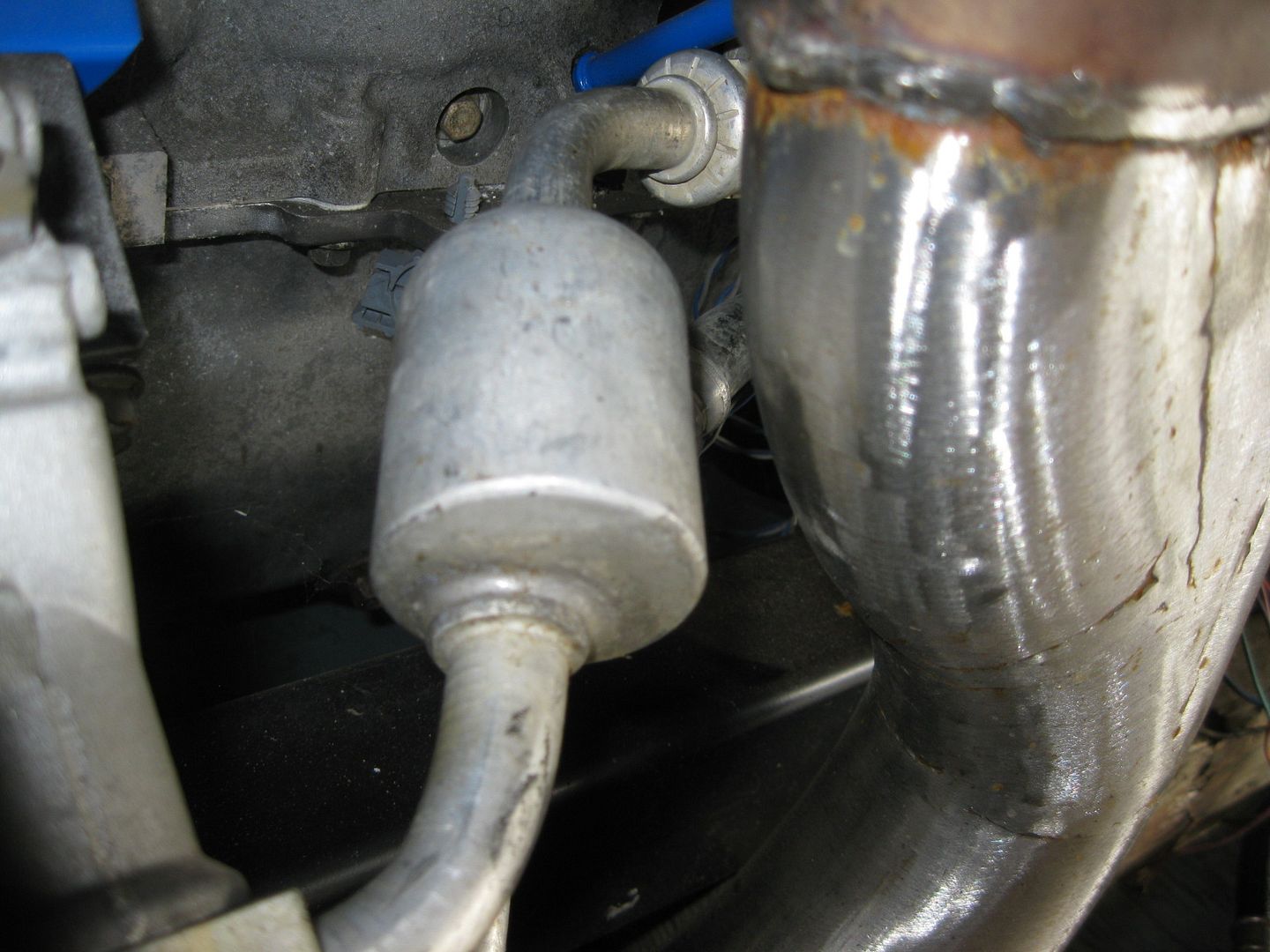
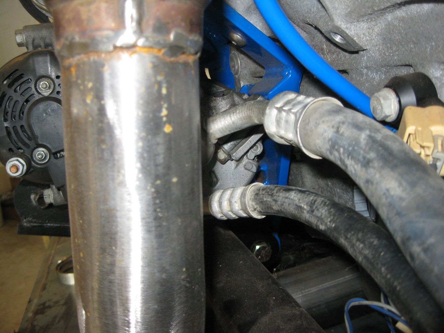
I probably could have pulled it outward, but there was plenty of unused room behind it and with that routing it would leave me with room to get my hands up there to change the plugs some day. I already have some new AC hose in a box, so I will just cut the current hose off, install some new hose and cut it to fit with the stock fiero chassis ends.
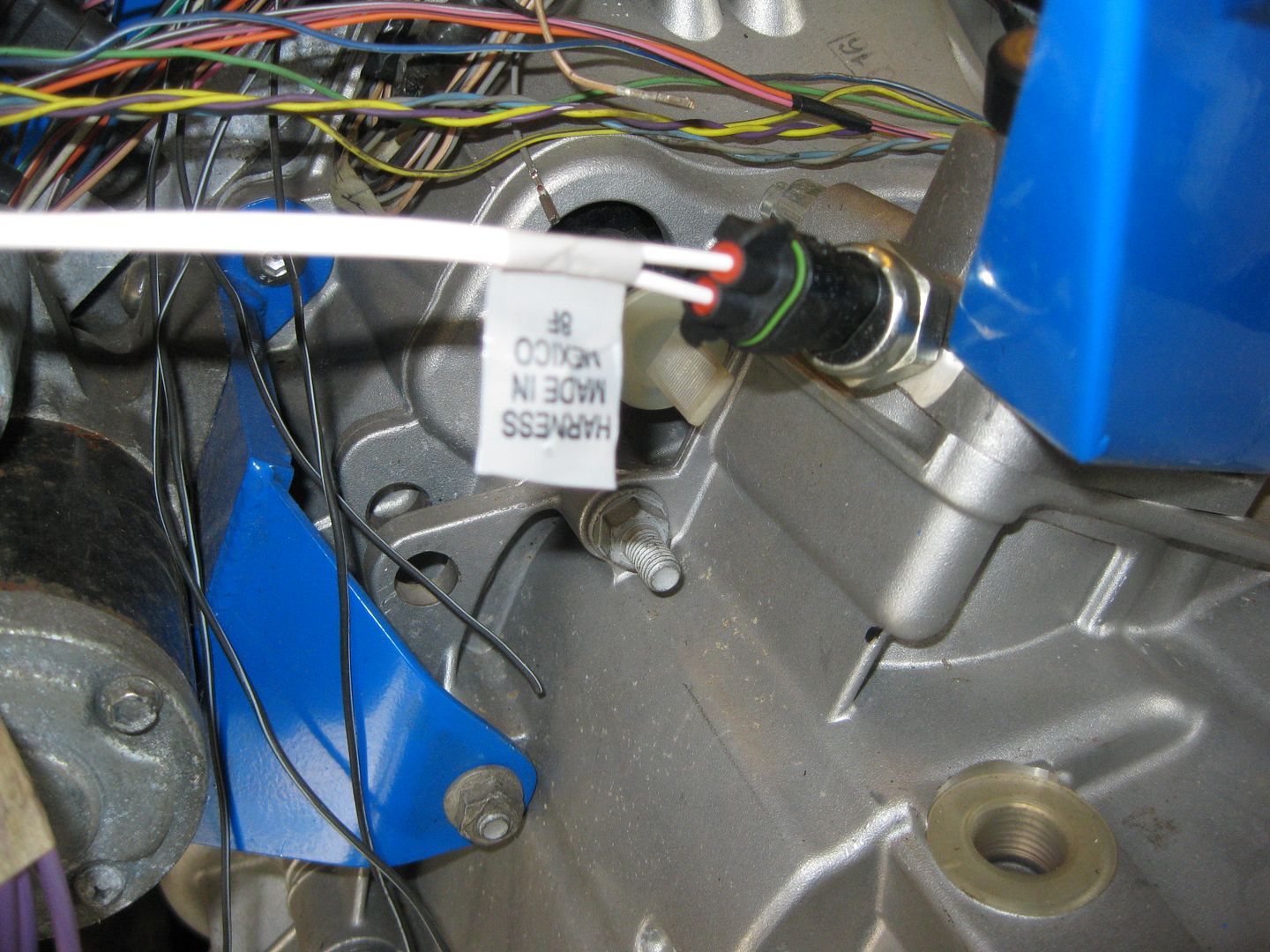
I really hate wiring and am somewhat fanatical about how it looks. It should be hidden as much as possible, the harness should be as small & skinny as possible and there should be a logical flow for the wires that can be seen (and the ones that can't). So here is a peak at the start of the harness build:
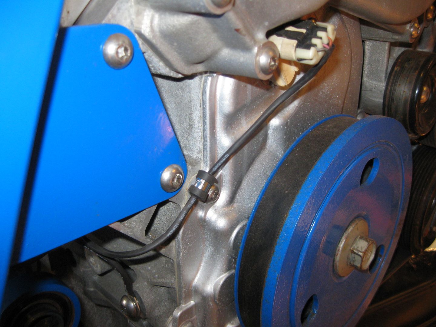
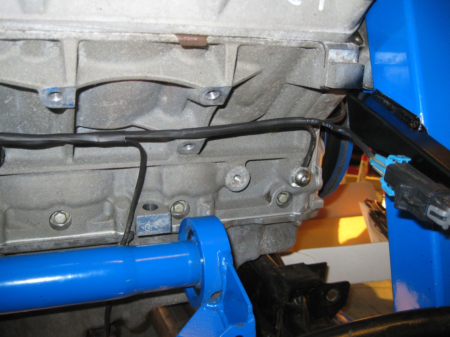
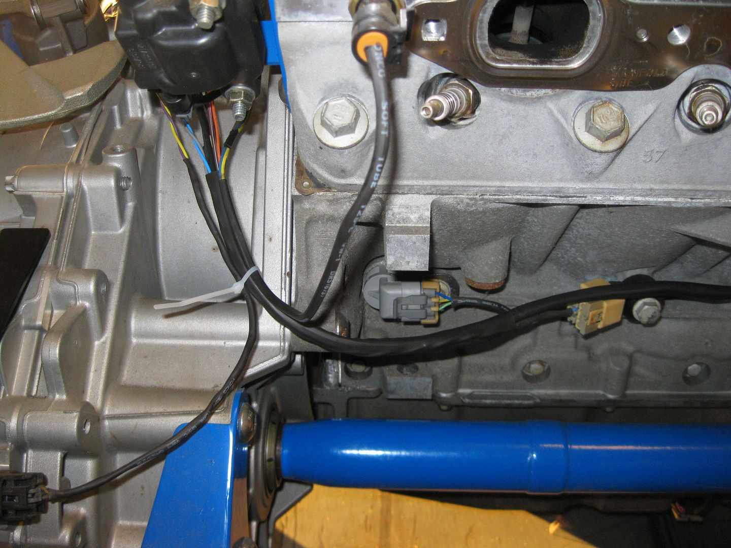
So far the Cam Sensor, Common Ground, ECM O2 Sensor, Oil Level Sensor, B2 Knock, and Crankshaft sensor have been loomed in heat shrink with the VSS and Temp portions getting ready to joint the harness. Lots more to do and the wires will start being added like crazy with the 4 coils and 4 injectors being added before reaching the center of the engine. The the ECM Oil Pressure sensor, DOD connector, MAF, DBW throttle and reverse lights at the center of the engine, then 4 more injectors, 4 more coils, map sensor and starter down the other side, then to the oil pressure sender for the gauge cluster, B1 knock sensor, alternator, and AC compressor.
Right now I am planning to completely eliminate the 500 connector. The rear lights/body harness with be spliced in directly to the body harness and the wires ran down through the fuel tank tunnel, into the double firewall panel, then through a hole I will drill in the B-pillar base, then the harness will be in the passenger wheel well and continue the stock routing path. This setup is very similar to how I ran the harness on my Ramjet/Getrag swap. The engine side of the 500 will probably just be a terminal strip in the console where the ECM used to go. Plenty of room for it and this will keep the size of the harness that needs to pass through the firewall as small as possible.[This message has been edited by fieroguru (edited 08-30-2012).]
|
|
|
|
Bloozberry
|
SEP 02, 08:53 PM
|
|
|
One of the things I like the most about this thread is your high quality pictures. It can easily take as much time to set up, take, crop, resize, and post the pictures as it often does to actually work on the car, something that not many people are willing to do.
|
|
|
|
fieroguru
|
SEP 03, 09:04 AM
|
|
| quote | Originally posted by Bloozberry:
One of the things I like the most about this thread is your high quality pictures. It can easily take as much time to set up, take, crop, resize, and post the pictures as it often does to actually work on the car, something that not many people are willing to do. |
|
Thanks! For me it is just part of the process of documenting so I have some references to go back to at a later date (especially part #'s for the components I used) and to help others follow along. My commentary also helps me remember what I was thinking at the time.
As for the time to get all the pictures... It took some trial and error, but now I have it setup were I literally shoot the pic, upload it (multiple at a time) and copy/paste the link without having to do any resizing/cropping/editing to the pics. I have a camera for car stuff and I set it to a lower resolution since they will be uploaded anyway (and I get more pictures capacity per SD card). Then I setup my photobucket account to auto convert every picture uploaded to a preset size. Once the upload is complete, it automatically gives me the link to the picture with the proper tags so it is a copy/paste.
I am sure I will get ragged on for not using PIP and hosting the pictures through PFF... but the issue is I share these pictures on multiple forums. The ones hosted on a PFF server are not allowed to be hotlinked from any other forum - they are for PFF only. If you try, you get this for all your pictures:

So to post the pictures anywhere else but PFF, I have to use something like photobucket and can't justify the extra effort to upload every picture to two separate servers.
|
|
|
|
fieroguru
|
SEP 03, 09:23 AM
|
|
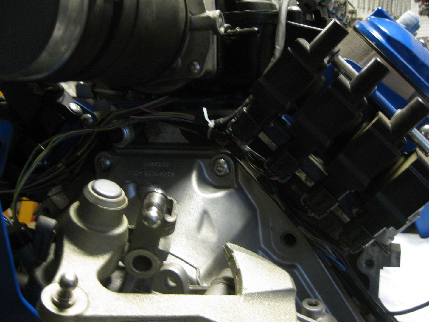
Made a little more progress with harness building and I am up to the point of the even # injectors joining the harness and you can see that I am trying to keep the harness tucked up close to the engine and hidden under the coils. This portion of the harness will be loomed in the normal automotive slip loom material.
I started the process of typing up all the terminations for the 3 connectors at the ecm and adding the termination point at the other side. Long tedius process but it lets be blow apart the harness and route it like I want it wire by wire. It also allows me to see what information I still need to track down... Like the Tach output for the E67 ecm I am using. The LS4 service manual does not list a specific tach output from the ECM as that signal is handled through the GMLAN. However, there were at least 3 other E67 applications that had a dedicated tach line from the ecm (GMPP crate motor ecm, TBSS and CTSV) - all of these have the tach wire installed at C1 Pin 25. Also, the VSS normally goes through the TCM, but the CTSV and TBSS had manual transmissions and connected the VSS directly to the E67 ECM at C3 Pin 66/67 with the output at C1 pin 39. Now I just have to figure out how to enable those functions w/o losing DoD...
|
|
|
|
Danyel
|
SEP 03, 12:07 PM
|
|
Added to my favorites .... PM sent about the F40 ... I also agree with Bloozberry 
------------------

My Build Thread
Tylers Toy[This message has been edited by Danyel (edited 09-03-2012).]
|
|
|
|
fieroguru
|
SEP 08, 02:37 PM
|
|
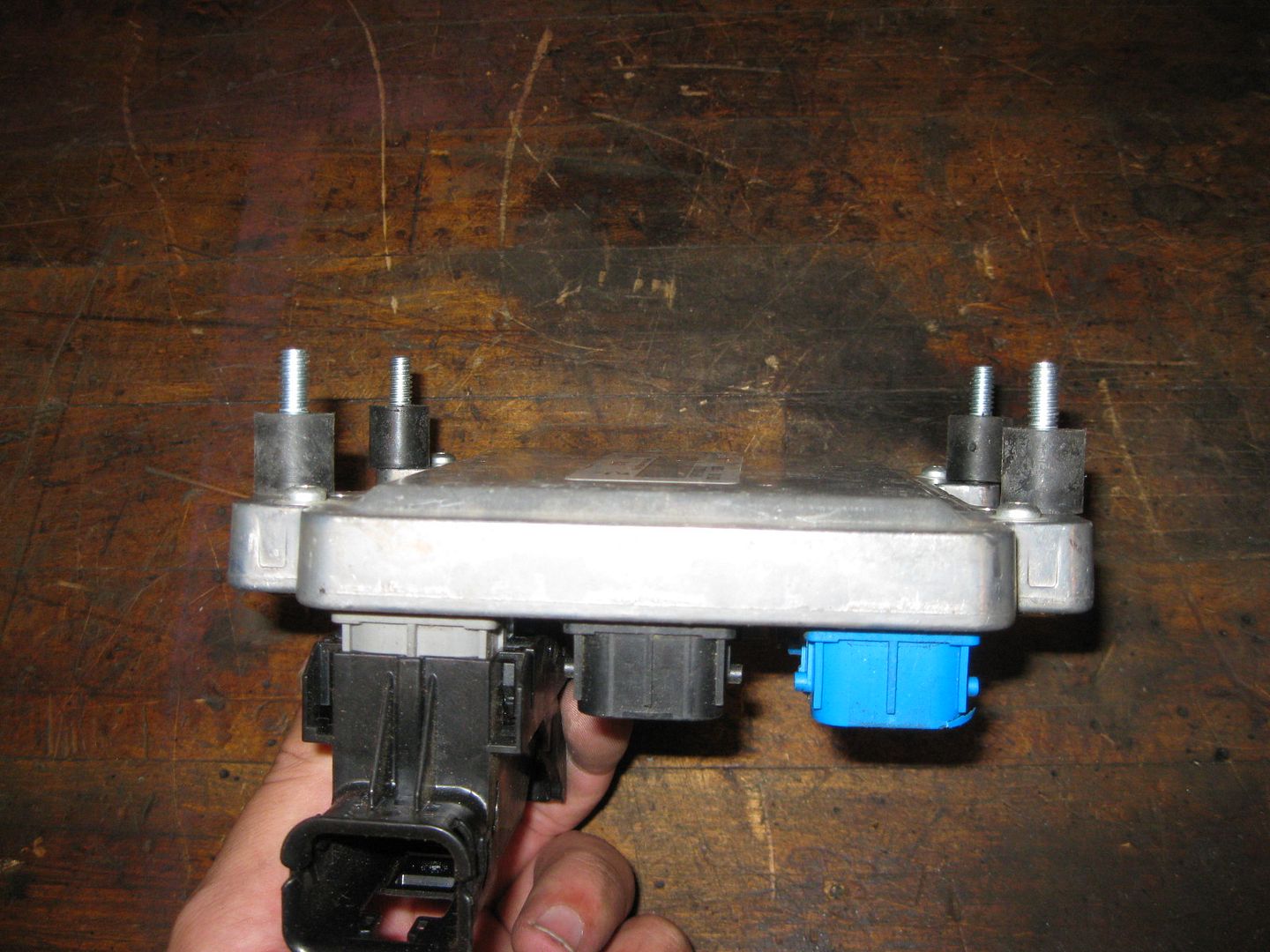
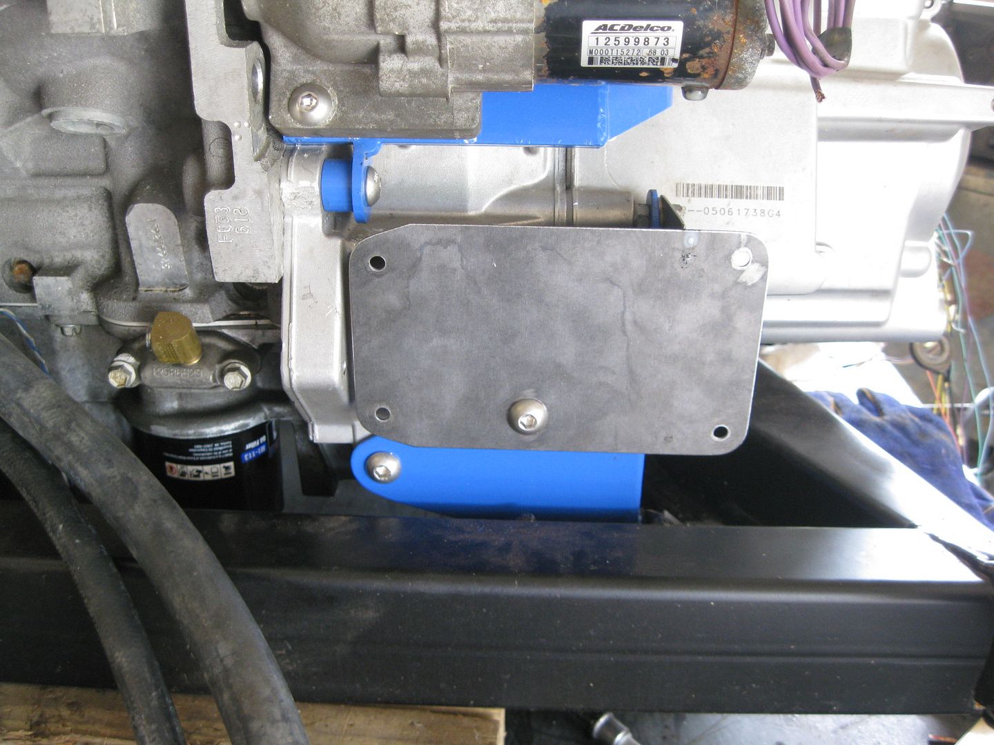
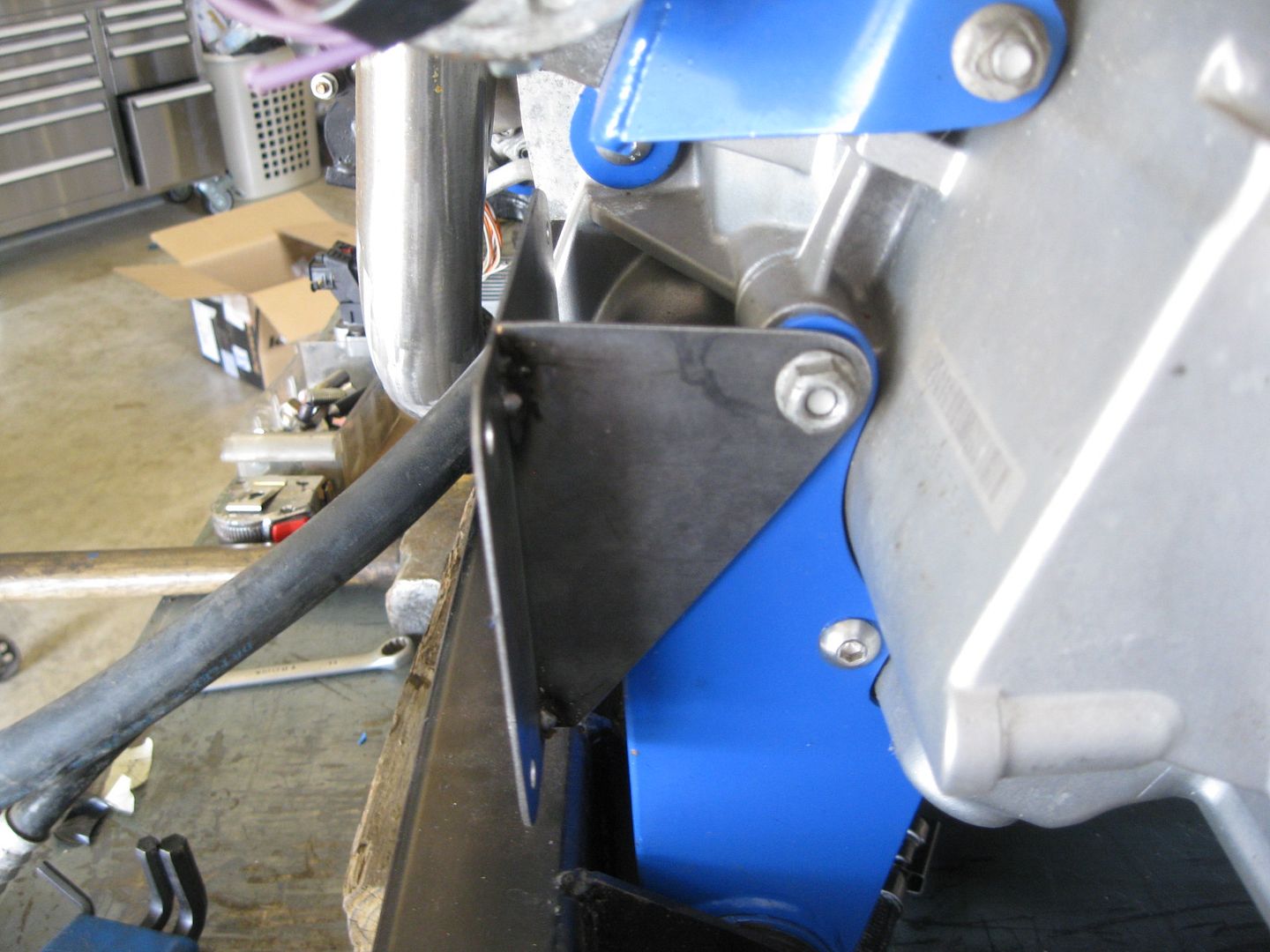
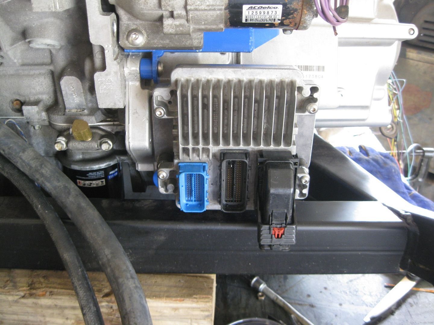
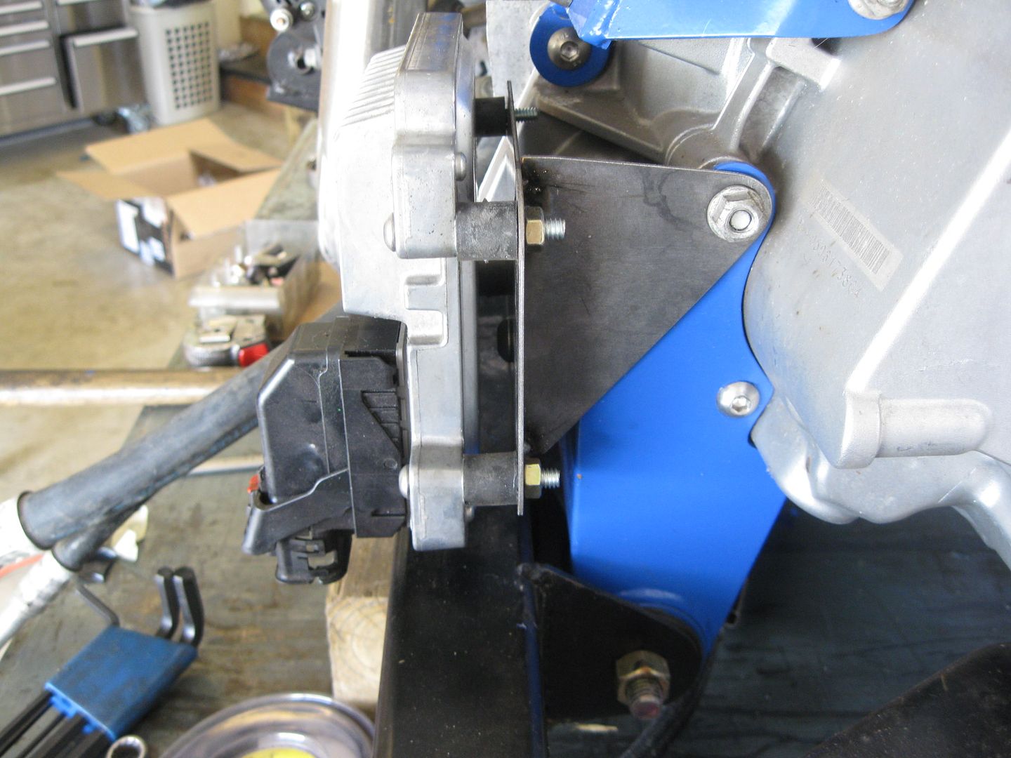
I was able to fab up the ecm mount today. It uses two of the front transmission mount bolts and has spacers between it and the blue transmission mount. The rear tab is just tack welded in the place for the pic:
|
|
|
|
F355spider
|
SEP 08, 09:39 PM
|
|
|
Is that AC hose from the LS4? Does it fit the Fiero connection?
|
|
|
|
fieroguru
|
SEP 08, 10:16 PM
|
|
| quote | Originally posted by F355spider:
Is that AC hose from the LS4? Does it fit the Fiero connection? |
|
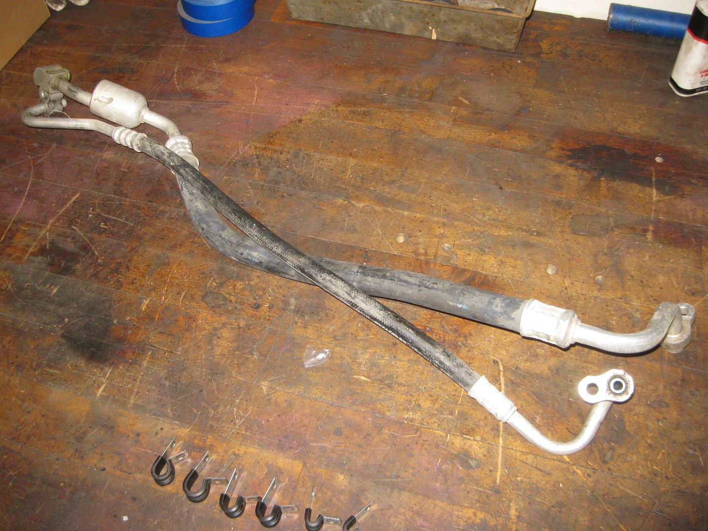
Yes, that is an OEM LS4 AC hose, no the other end will not fit the fiero chassis connection. I am planning to remove the hoses, install new ones with the needed fiero end.
|
|
|
|
fieroguru
|
SEP 11, 07:39 PM
|
|
|
|
|