 
     |
| NS F355 Project (Page 40/73) |

|
Yarmouth Fiero
|
JUN 18, 02:52 PM
|
|
|
Thank you for the information sir. Great picture too.
|
|
|
|
Yarmouth Fiero
|
JUN 18, 03:05 PM
|
|
|
|
|
fieroguru
|
JUN 18, 03:54 PM
|
|
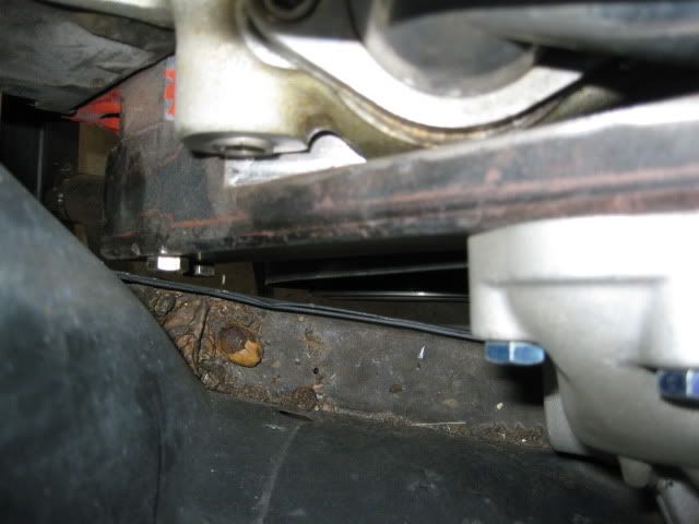
I always place the engine/transmission as low as possible and try to get the oil pan flush with the bottom of the cradle.
Here is a picture of the crankshaft centerline well below the bottom of the frame rail:
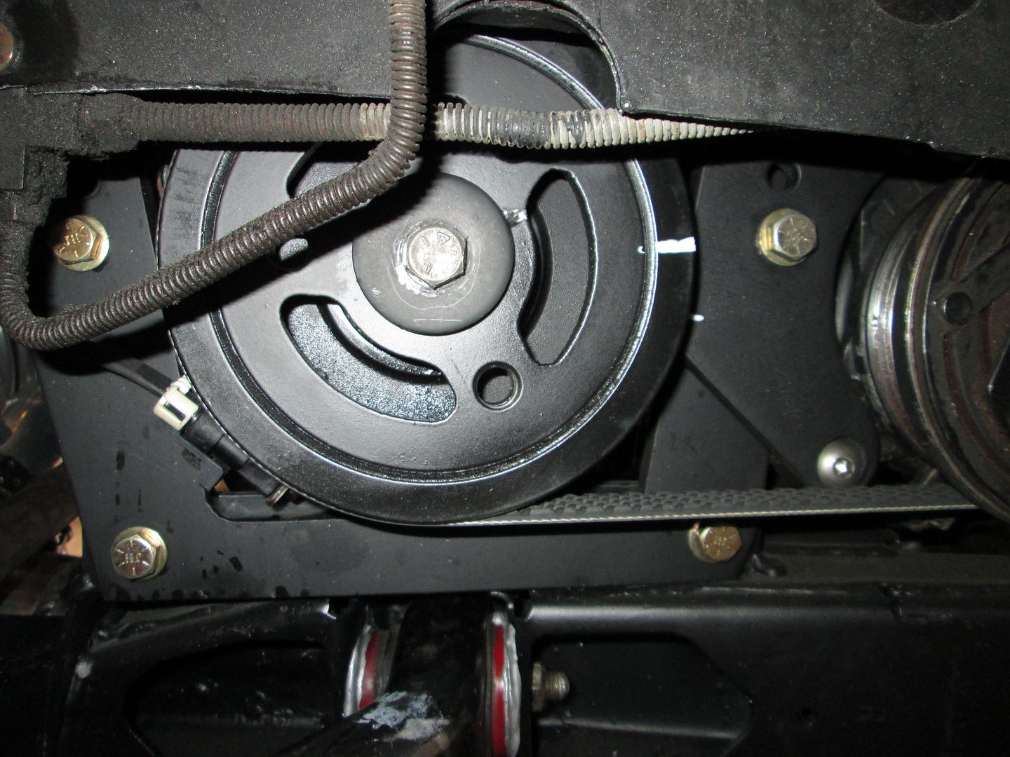
The engine still needs to be further to the PS frame rail. There normally is about 1 3/4" between the 2 rear water pump bolt holes on the engine block and the frame rail. Your accessory drive shown should be nearly completely through the DS frame rail (that is unless you want to notch the DS frame rail for transmission clearance):
|
|
|
|
Bloozberry
|
JUN 19, 03:22 PM
|
|
Way cool drawings there Graham... way cool.
You've just discovered the difference between Archie's V8 adapter kit and the Zumalt knock off kits. The Archie kit with the thicker adapter plate ends up making the water pump pulley interfere with the lower frame rail on the passenger side, so his solution was to extend a shaft from the ends of the crank and water pump pulleys to relocate the pulleys on the outside of the frame rail. Later options included low profile electric water pumps. The Zumalt kit used a thinner adapter plate, a shorty-style water pump with a single V-belt drive pulley on the crank, which kept the pulleys inside the engine bay. That however necessitated a notch in the driver's side lower frame rail to accommodate the transmission though. So there are pros and cons to either approach with the bottom line being that there simply isn't enough room between the frame rails without some compromises.
The adapter I sold you several years ago is an Archie style adapter, though I'm not certain who actually made it.
|
|
|
|
Yarmouth Fiero
|
JUN 19, 03:30 PM
|
|
Thanks Blooze. The 3D is alot of work but its so easy to move things around once they are drawn. The engine model is a generic engine set up. I had always thought about using a remote electric water pump and I don't have any air conditioning or power steering so the belts and pullys will be minimal. I'm still searching for a good 3D model of the 6 speed manual gearbox. I suppose the adapter plate I have now may not suit that.  With regard to frame chopping, I've gotten good at that so I don't mind doing whatever is necessary once I have my engine and transmission sitting in my garage. I am still thinking that I'll move the strut towers out in hopes that it provide a little more room for whatever I may decide to do next. With regard to frame chopping, I've gotten good at that so I don't mind doing whatever is necessary once I have my engine and transmission sitting in my garage. I am still thinking that I'll move the strut towers out in hopes that it provide a little more room for whatever I may decide to do next.[This message has been edited by Yarmouth Fiero (edited 06-19-2014).]
|
|
|
|
HarryG
|
JUN 19, 04:11 PM
|
|
| quote | Originally posted by fieroguru:
I always place the engine/transmission as low as possible and try to get the oil pan flush with the bottom of the cradle.
Here is a picture of the crankshaft centerline well below the bottom of the frame rail:
|
|
That looks like Archie's front mount; do you modify it to gain more adjustability?
|
|
|
|
fieroguru
|
JUN 19, 04:22 PM
|
|
| quote | Originally posted by HarryG:
That looks like Archie's front mount; do you modify it to gain more adjustability? |
|
Yes. I cut 1/2" off the very bottom, filled the half holes and drilled 2 new mounting holes. I also cut 1/2" off the bottom of the adapter plate and notched the cradle for the starter.
|
|
|
|
fieroguru
|
JUN 19, 04:31 PM
|
|
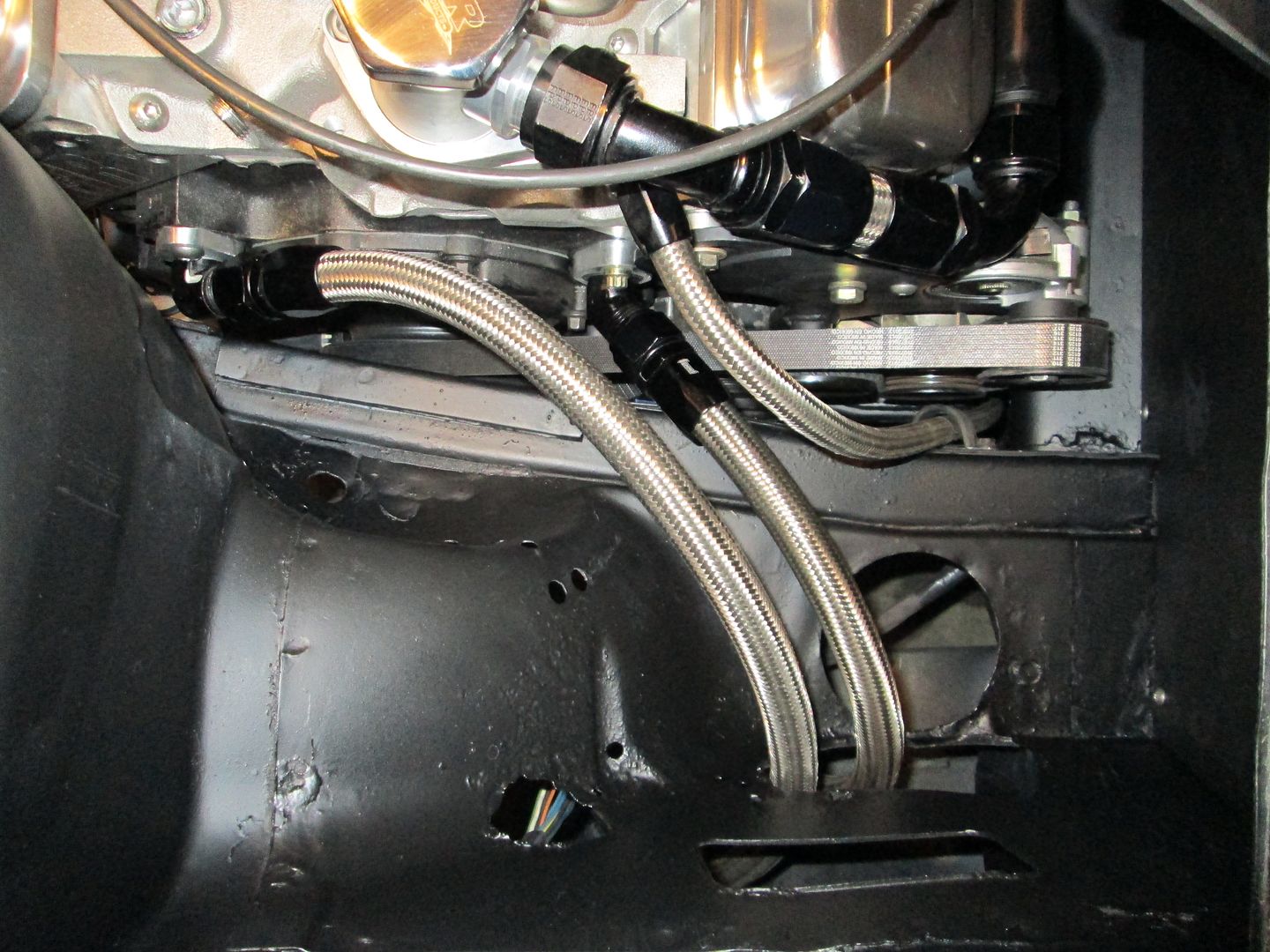
If you mount the engine with the oil pan close to being flush, then the strut towers don't cause any interference issues.
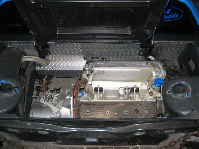
Since you want to do a SBC/F40, you might find this thread beneficial as that was my plan too before I went to the darkside (LS4).
http://www.fiero.nl/forum/A...120111-2-099565.html
I was using a 1/8" adapter plate and a serpentine belt drive with the L31 timing cover and barely fit within the stock frame rails. With the Zumalt adapter plate, you probably have room for a V-belt balancer and the F40. The serpentine balancer or the Archie adapter plate will require a frame notch on one side or the another.
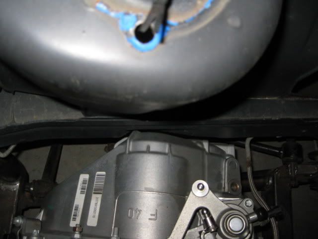
Here is a overall picture of the SBC/F40 combo - notice the engine is further to the DS than the earlier SBC picture I posted. Then pictures of the clearance on each side.
|
|
|
|
Yarmouth Fiero
|
JUN 19, 08:37 PM
|
|
|
Wow, that is certainly a tight fit. Thanks for the photos Fieroguru. Hopefully my 3" chassis stretch may help a little in way of reducing frame interference.... but clearly not enough.
|
|
|
|
Yarmouth Fiero
|
JUN 23, 09:12 PM
|
|
Keeping with the theme of moving the strut towers outward about 3" per side to match the increase in track width, I started removing the sheet metal connecting the upper and lower frame rails forward of the strut towers. The stock sheet metal is arched to form the wheelwells on both sides of the engine bay, however, with the increase in the rear track, there is going to be plenty of room to square the replacement sheetmetal off thus providing a little more room in the engine bay.
Here are a couple screen shots showing the difference in stock and revised strut locations as well as the difference in chassis sheet metal from stock to revised.
Stock strut tower and sheet metal


Proposed strut tower and sheet metal


My chassis has been essentially clear of any rust but as I started removing the sheet metal, lo and behold, there was some rust on the inside face of the upper frame rail. Its easy to see why the Fiero chassis is so susceptible to rust in this location. Clearly the chassis design is deeply flawed with regard to rust prevention.... much like all three of my Grand Caravans over the years. 


I'll repeat this process of sheet metal removal on the passenger side while retaining the strut towers in the best possible condition for reuse.
|
|
|


