One of my major vices is I can't stop messing with stuff... After a while, I just have the need to upgrade a perfectly good setup just to build something different.
My SBC Fiero is my pride and joy and has had a seemingly endless list of upgrades over the years. It was purchased Jan 1, 2000 for $800 as a rust free 88 Coupe with 2.5/Isuzu and I stopped keeping track of $$$ spent on it several years ago... its just an entertainment expense now. Here is the history of the major upgrades:
2001 2.8 V6/Isuzu, full GT Fastback Clone conversion interior & exterior, Mille Miglia MII 16x7 wheels and 245/50/16's. 2002 4.5 Cadillac V8/Isuzu, blue accenting for interior 2003 283 Carbed SBC/Isuzu with electric water pump 2004 350 Carbed SBC/Isuzu with custom mechanical water pump, Spec Stage 3, dual A-pillar gauges, DKOV carbon fiber headliner 2005 350 Ramjet SBC/Getrag with Hydraulic TOB, Spec Stage 2+, 2x3 cradle crossmembers, rear sway bar, 12" Vette Rotors, full Suspension rebuild and poly upgrade front/rear, Corvette Seats, 26x19 radiator upgrade, Blue exterior paint, WRX hood vent, Aus Stage 2 side panels, relocated 500 connector to console area and moved firewall harness down by shifter area 2006 - Nothing... moved to KY 2007 - installed rebuild Getrag, Spec Stage 3+, aluminum firewall, cold air intake, relocated battery under passenger headlight, custom hood vent, started doing my own tuning. 2008 - new box for the battery relocation, started on 180 SBC headers
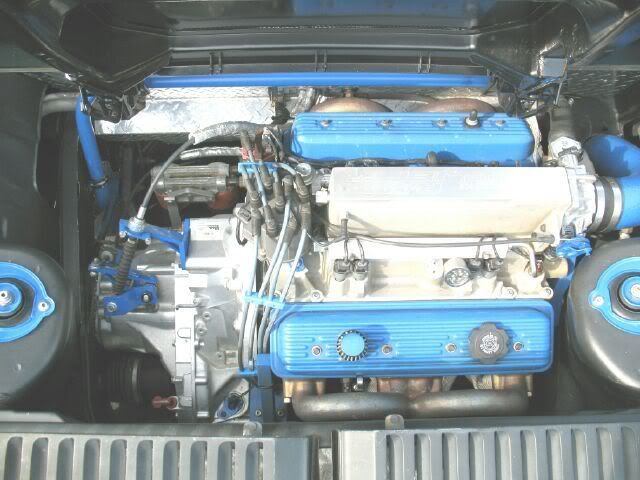
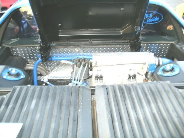
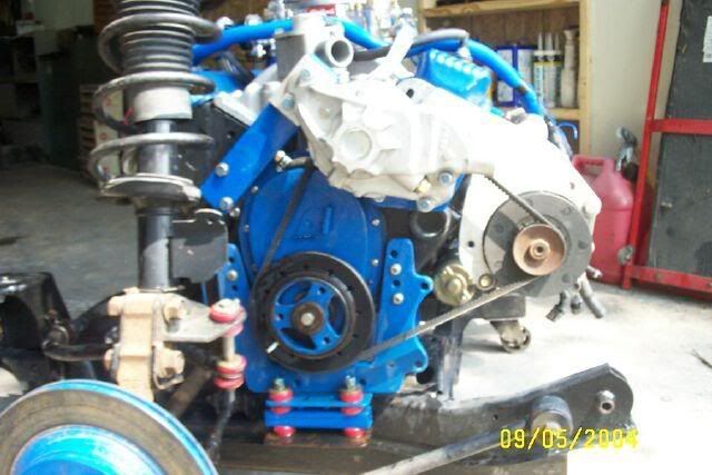
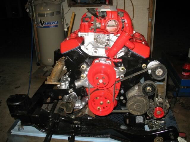
Here are some 2008 pics:
For 2009-2010, there will be a major transformation to the drive train and pretty much everything but the engine itself is slated for upgrading (and the engine might be too if the funds are available).
Planned upgrades are: 1. F40 6 speed with tranny mounted starter 2. Custom SBC adapter plate designed specifically for the F40 and interchangeable between SBC and LSx engines. Also includes integrated mounts and diff support 3. Custom Small Diameter SBC Flywheel for F40 4. Spec Stage 4 clutch – solid hub with ring friction material – (no 6 puck) 5. F40 Axles modified from 99 Saab 9-5 axles 6. Poly Engine & Tranny Mounts 7. Modified 3.1 balancer and custom accessory brackets for serpentine drive 8. 88 2.5 Alternator and AC compressor 9. Duplicate of current custom water pump 10. Custom 180 equal length headers and dual 3” exhaust 11. Custom 88 tubular cradle 12. OBDII 411 LS1 ECM/engine management 13. More engine bay simplification and beautification
Since I am married with 2 daughters in diapers, funds available for this project are quite limited and spending any $$$’s for any kits is out of the question. This will be a very fabrication intensive project to keep the $$$ requirement down, but it will be at the expense of time… which is why it probably will not be fully completed until sometime in 2010. Several methods of mockup will be used to allow the Fiero to remain drivable atlteast through the summer 2009.
To help keep this thread orderly for future reference, I will break it down into a bunch of subsections and each sub section will have a dedicated post on the 1st page that will be updated as things progress. This will provide a single page build summary on page 1 with more details, commentary, and trial and error on the following pages of the thread.
The Ground Rules: 1. I know there are easier, tried and true methods/options, but I want to make something truly unique with an original design. 2. No kits will be purchased, almost everything will be fabricated to help keep costs down, plus the design deviations require custom parts. 3. It will be SBC based. It will be a few years before I go into LSx arena, and have no desire to put any other engine in my 88 GT Clone at this time. 4. Overall weight will be kept to a minimum within reason and the limitations of fabrication and cost. 5. Overall length of the SBC and F40 will be kept to a minimum, but space will be provided for a serpentine belt drive. 6. The full trunk will be retained and left unmodified 7. Car is being built for reliable daily driving (my current SBC install has 40K on it). 8. I have no intention of selling SBC kits, but really enjoy the R&D and fabrication.
[This message has been edited by fieroguru (edited 04-19-2009).]
IP: Logged
12:48 PM
PFF
System Bot
fieroguru Member
Posts: 12550 From: Champaign, IL Registered: Aug 2003
Adapter Plate The adapter plate is where things become really different. In fact my design has 7 significant differences from any available SBC kit:
1. F40 Specific design 2. Thickness of 1/8" 3. Starter moved to Transmission 4. Interchangeable between SBC and LSx (except LS4) 5. Tranny Differential rotated up 1" 6. Rubber mounts integrated into adapter plate (no tranny mounted mounts) 7. Differential supported via adapter plate.
Archie's SBC manual kits uses an adapter plate about 1" thick because the kit is based on using a 153 tooth ring gear that will not fit within the FWD manual transmissions. My current SBC setup is using an Archie Economy kit and it has worked flawlessly for 40K miles... It works very well, I just wanted a thinner overall package and some of the other features that a complete redesign would allow.
Z-Style SBC manual kits use a thinner adapter plate (1/2 to 5/8") and a custom small diameter flywheel with a Nissan ring gear and starter. The manual kits are very tight within the Getrag, Muncie or Isuzu transmission and this lack of space required some design compromises with the flywheel (very thin and counter sunk flywheel bolts). It is also important to use the proper clutch, or there will be more interference issues. I have a Z-style kit in my 4.3 Fiero. While I think the thinner adapter plate was a step in the right direction, it really should have been in the 11/16" to 3/4" range and most of the compromises could have been avoided (I shimmed mine to 3/4" when I installed it).
Both of these style of SBC kits were originally designed in the mid to late 80's and were designed around the available transmissions of the day.
Here are the details about each of the 7 design features:
F40 Specific design My adapter plate is being designed specifically around the F40 6-speed. Mainly because the increased bellhousing depth will allow a much thinner adapter plate and decrease the overall length of the SBC/F40 swap. My adapter plate WILL NOT WORK with any other FWD manual transmission... only the F40.
Thickness of 1/8" The restriction to the F40 transmission with its increased bellhousing depth, allows an adapter plate in the 1/8" thick range. This will be the thickness between the SBC block and the transmission, but the adapter plate could be built up thicker within the bellhousing recess of the SBC to provide more stiffness if needed.
Starter moved to Transmission The next major design variation is to move the starter to the transmission side of the adapter plate. Both Archie and Z-Style kits require an oil filter relocation kit to move the oil filter to make room for the starter on the engine side. Moving it to the tranny side will allow the filter to remain in the stock location... less parts, hoses and chances of leaks.
Interchangeable between SBC and LSx (except LS4) The starter move, also allows the same adapter plate to work for LSx based engines (except LS4). The bolt pattern between SBC and LSx is the same, except for the additional lower bolts on the LSx and the bolt heads that protrude from the LSx rear cover (just need to drill clearance holes in the adapter plate for these). The issue with the LSx swap is starter clearance with the Y block. By moving the starter to the tranny side, this issue goes away entirely and provides the opportunity for SBC/LSx interchangeable adapter plates (but would require engine specific flywheel designs due to different crank protrusions).
Tranny Differential rotated up 1" I like to have my engines as low as possible. My current SBC setup has the engine centerline 8 1/4" above the bottom of the cradle. This puts the half shafts at an upward angle as they go toward the wheels and becomes even worse if you lower the car. By rotating the tranny and raising the differential the angle of the half shafts can be lessened. This is only possible with an intermediate shaft, because the Fiero inner tripod is very close to the stock SBC starter pad and it limits the opportunity to do this rotation.
There have been some kits in the past that rotated the tranny the other way - mostly for the automatics to reduce the amount of the starter pad that needed to be cut off to clear the auto tranny.
Rubber mounts integrated into adapter plate (no tranny mounted mounts) The adapter plate will be more of a mid-plate type design in that it will be sandwiched between the engine/tranny and extend out on the sides. The adapter plate will extend to the general locations of the crossmembers and allows the inclusion of the mounts into the plate.
Differential supported via adapter plate. Since the adapter plate will be extending past the differential, why not weld on bosses that will pick up the perimeter bolt pattern on the F40 differential. This was a common failure point of the getrag and while the F40 has much more material in this area, it wouldn't hurt to bolt it to the adapter plate as well.
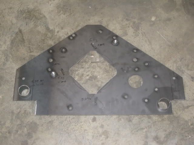
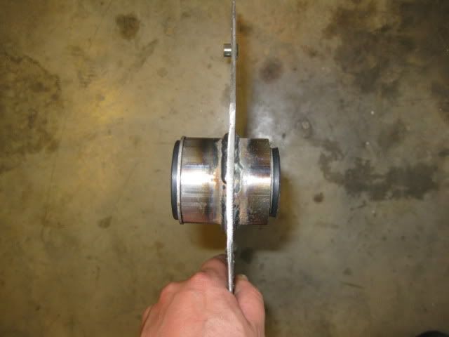
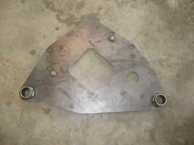
Here is the rough shape of the adapter plate after all the bellhousing, differential, axle and mount holes have been located.
Bushing sleeves welded in:
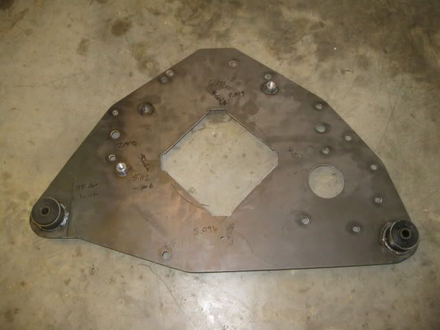
Then the adapter plate was trimmed down closer to the final contour:
Bushings installed:
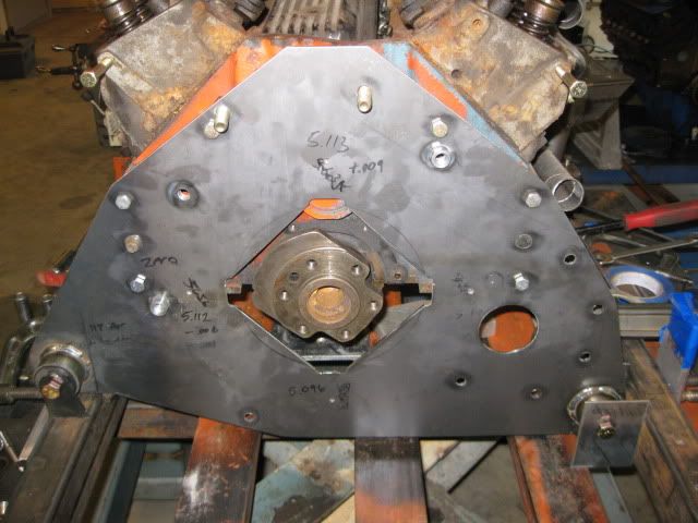
Adapter plate back on the engine with some rough shapes for the rear tranny mount:
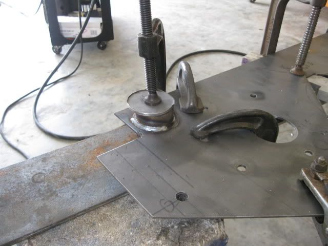
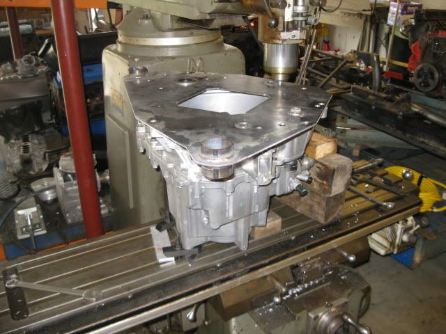
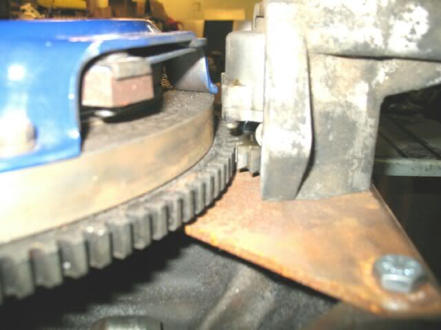
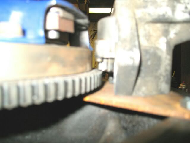
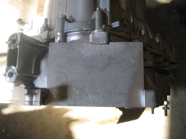
Next it was back to the tranny to clearance the bellhousing flange for 2 SBC bellhousing bolts. Put the tranny up on the mill, leveled it and clamped it down, placed the adapter plate on the tranny and located the first 3/8" bellhousing hole.
Then used a 3/4 end mill to make the needed bolt pockets:
[This message has been edited by fieroguru (edited 05-11-2010).]
IP: Logged
12:50 PM
fieroguru Member
Posts: 12550 From: Champaign, IL Registered: Aug 2003
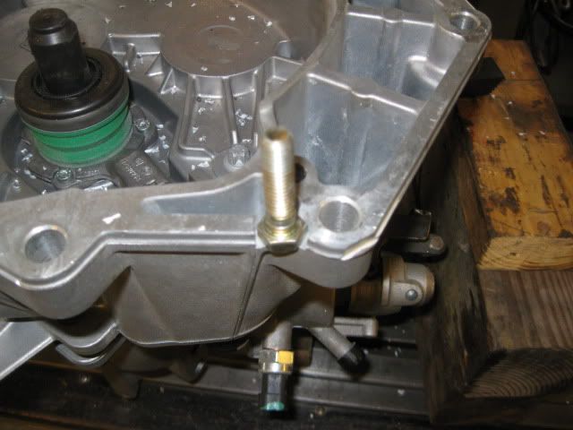
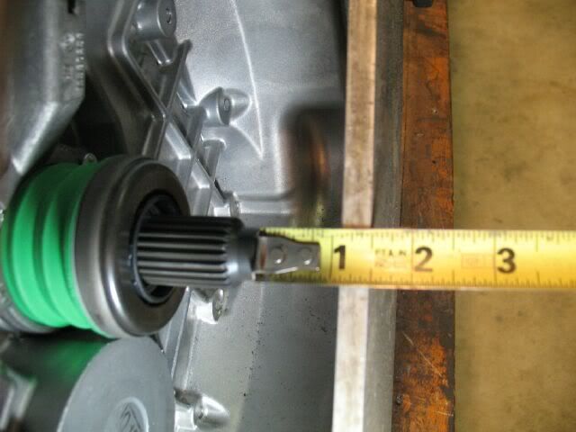
Flywheel & Clutch The F40 6 speed was designed for use with a thick dual mass flywheel and has a deeper bellhousing with a recessed input shaft. The input shaft has about 1 3/8” of usable splines that are from 1 ½” to 2 7/8” from the bellhousing face – this is a critical design dimension.
The SBC crank flange protrudes from the bellhousing face of the block by about 11/16” whereas most FWD engine flanges are within 1/16”. By using the SBC, about 5/8 of the needed depth is already obtained. The adapter plate thickness will take some if this gain back, but it is a step in the right direction.
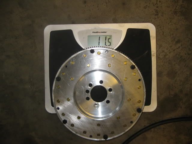
I happened to have a Hayes billet steel SBC flywheel with 153 tooth ring gear sitting on the shelf (from 9 years ago). With it bolted to the crank, the flywheel face is about 1 5/8” from the bellhousing surface. With a Spec Stage 2+ clutch on this flywheel, the clutch splines are 1 9/16 to 2 5/16” from the bellhousing face… right in the splined area for the F40, but without the thickness of the adapter plate accounted for.
The 1/8” adapter plate thickness will push the tranny splines away from the clutch splines 1/8”
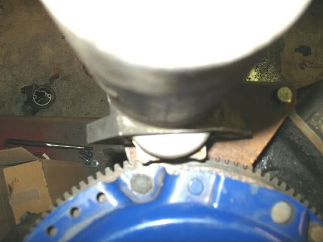
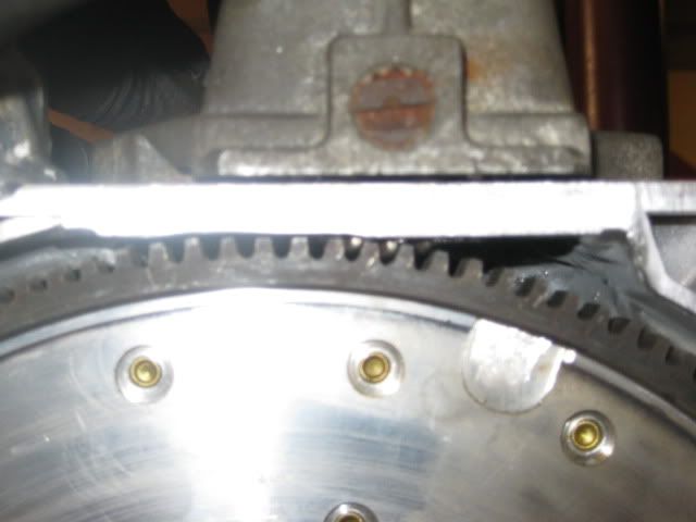
Here is a 153 tooth flexplate resting on an Isuzu bellhousing, as you can see it will not fit within the tranny:
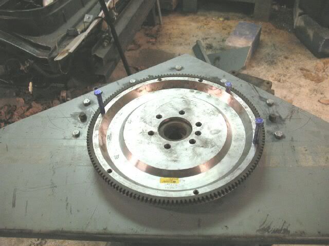
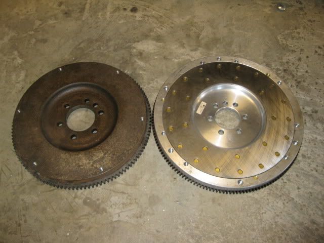
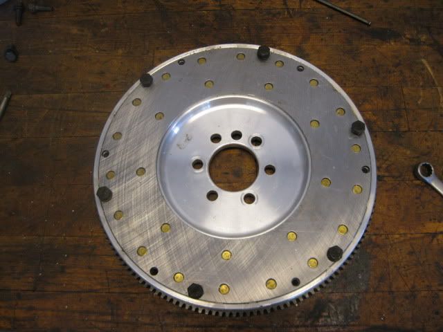
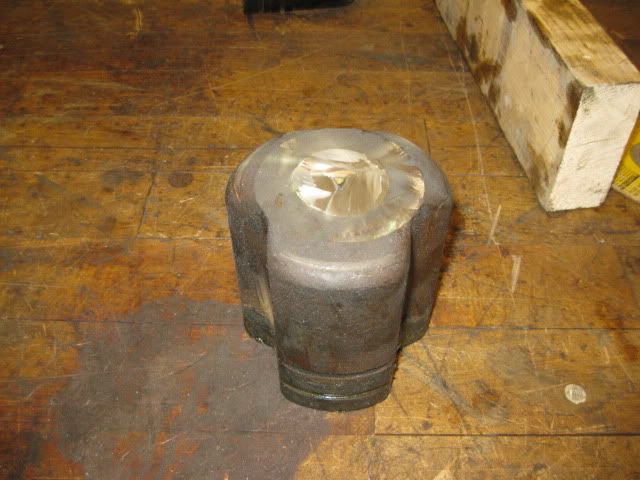
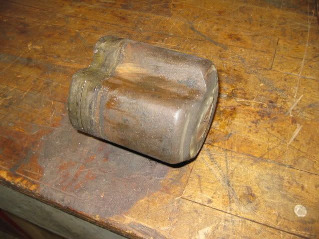
I had modified the billet Hayes flywheel for a pre 86 SBC using the Nissan Ring gear. When I switched to a Post 86 engine, I needed to make another flywheel so I picked up a 153 tooth 86+ SBC aluminum flywheel from McLeod for 220 shipped (ebay closeout sale). Here is the previously modified Hayes flywheel/Nissan ring gear and the new Aluminum one that needs modified;
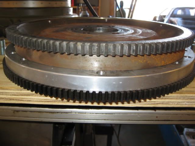
The list of needed modifications to use the aluminum flywheel are: Remove the 153 tooth ring gear. Turn down the OD of the flywheel so it will fit within the F40 transmission. Weld up all the pervious pressure plate bolt holes - none of these can be used. Turn down the ring gear landing - the Nissan ring gear has a smaller I.D. and would not allow the use of the stock balance plate on this flywheel, but the fiero one would so I switched to the Fiero ring gear. Heat up and install Fiero ring gear, then weld on the original ring gear tabs and drill/tap the hole Drill/tap the pressure plate bolt holes.
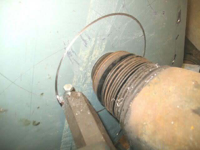
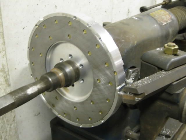
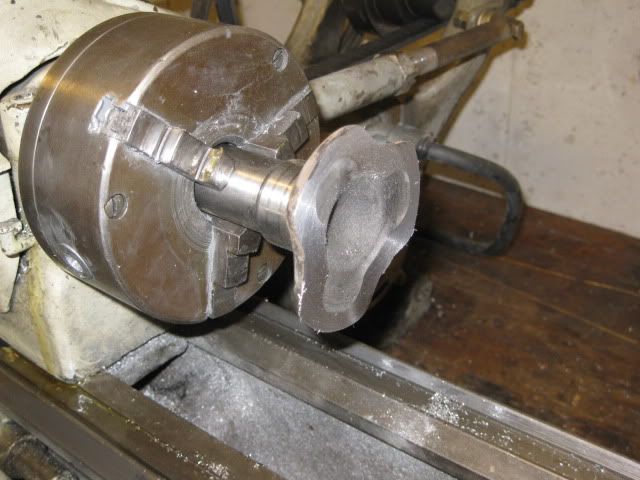
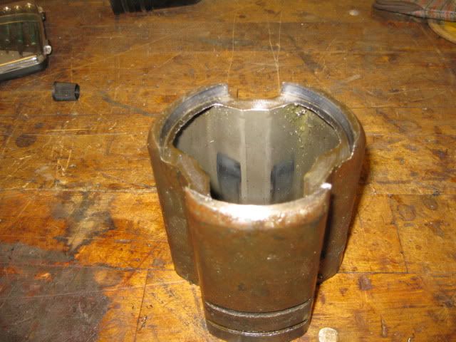
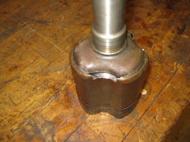
Here it was on the brake lathe turning down the OD:
Double checking the depth of the ring gear landing... go in too far and the ring gear will make contact with the bellhousing:
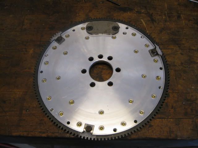
Finished flywheel:
[This message has been edited by fieroguru (edited 05-28-2010).]
IP: Logged
12:51 PM
fieroguru Member
Posts: 12550 From: Champaign, IL Registered: Aug 2003
Starter, Brackets and Tranny Modifications By moving the starter to the tranny, the adapter plates have the opportunity for interchangeability between the SBC and LSx engines (starter location is the main driver of the current differences). There would still need to be an engine specific flywheel (due to crankshaft protrusion differences and a slightly different crankshaft bolt pattern).
This tranny mounted starter will also be a solution to the people wanting to run a manual tranny on the LS4.
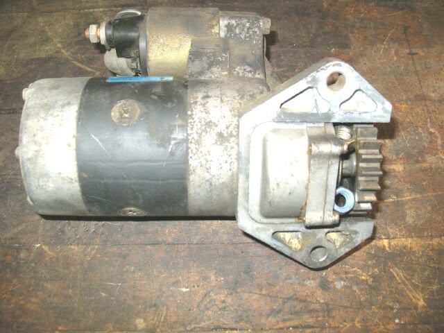
The biggest challenge with the tranny mounted starters is to find/make clearance to the tranny case for the starter and for the nose of the starter to clear the flywheel and pressure plate. Since my 4.3 swap, I have grown fond of the Nissan starters and ring gears (about 1/8” larger in diameter than Fiero ones). So I am planning to stick with the Nissan components.
The Maxima starter has a large diameter bendix, clears the current flywheel/pressure plate and has the proper engagement to the ring gear currently mounted to the flywheel:
When I switched to the Aluminum flywheel/Fiero ring gear, I switched to the Ford Taurus starter. It is also a tranny mounted starter with similar layout as the Nissan Maxima one, but this one has the proper teeth pitch to mesh with the fiero ring gear.
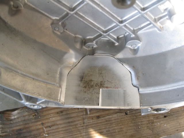
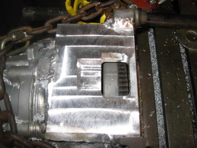
Original Starter Pad removed:
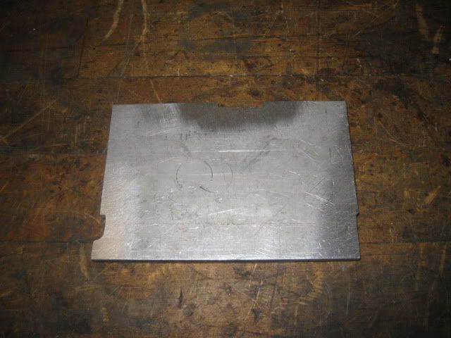
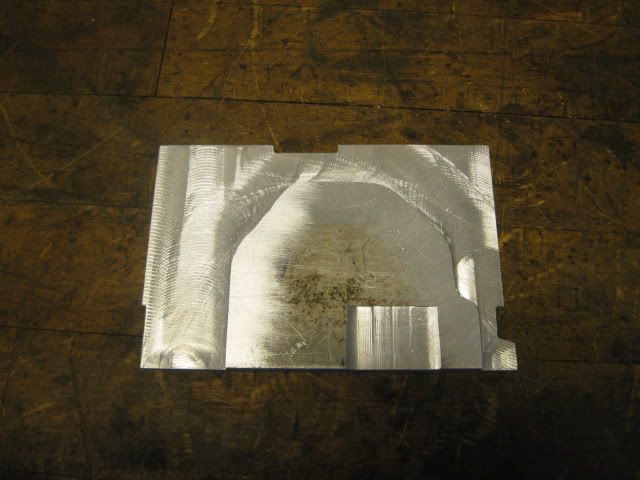
3/8" aluminum filler plate:
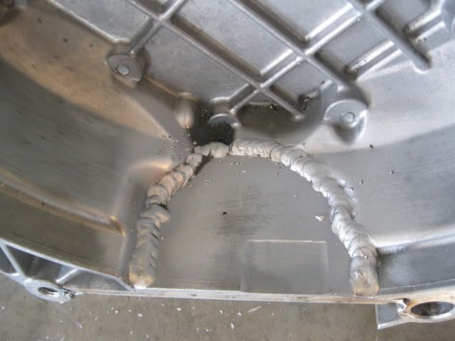
Then the pocket for the starter was milled for the proper gear mesh:
[This message has been edited by fieroguru (edited 05-28-2010).]
IP: Logged
12:52 PM
fieroguru Member
Posts: 12550 From: Champaign, IL Registered: Aug 2003
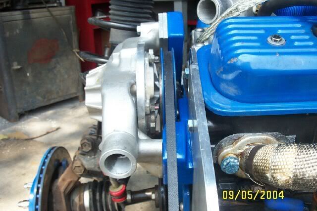
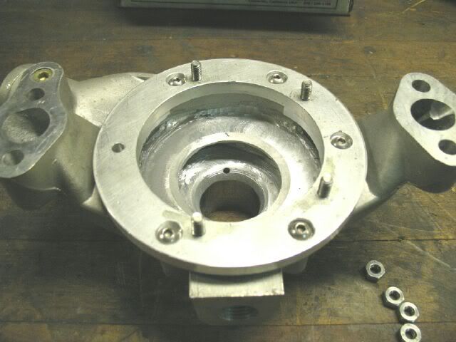
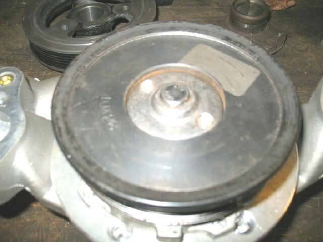
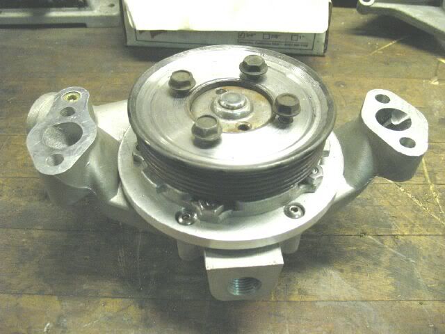
Water Pump and Offset Housings Russ Fiero (Russ Brown) and I co-developed this water pump design back in 2004. He had already experimented with some offset housings to move a traditional SBC pump away from the wheel well, but still retained a stock SBC water pump. I was messing around in my parts bin of water pump stuff and came across some water pump insert and had the idea of putting in on the backside of the SBC housing in conjunction with the offset housings to make a back side driven water pump. Russ found the 3.1 water pump insert (which was a better fit than the one I had) and did the needed machine work to the SBC housing to make it fit. Then I took the pump and fabricated the needed offset housings to mount the pump so it clears all the sheet metal and could be belt driven directly from the Archie crank pulley. This original pump is nearing 35K miles and has proven to work very, very well.
Up until now, that pump had been a true 0ne-of-a-Kind. This new water pump will be the exact same, except use a serpentine pulley vs. a V-belt.
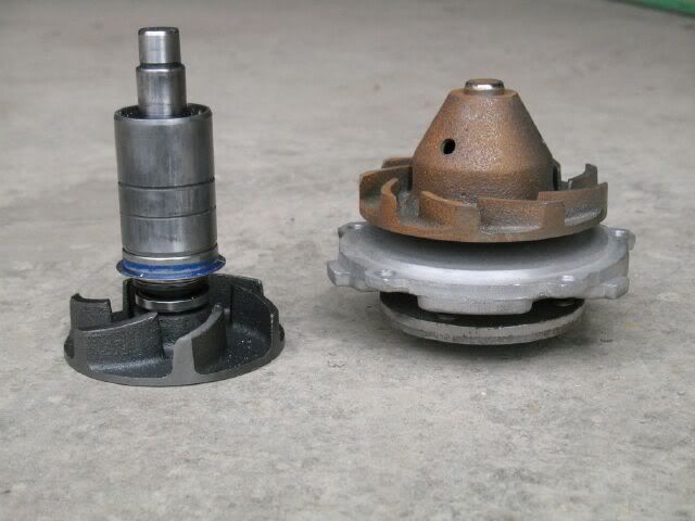
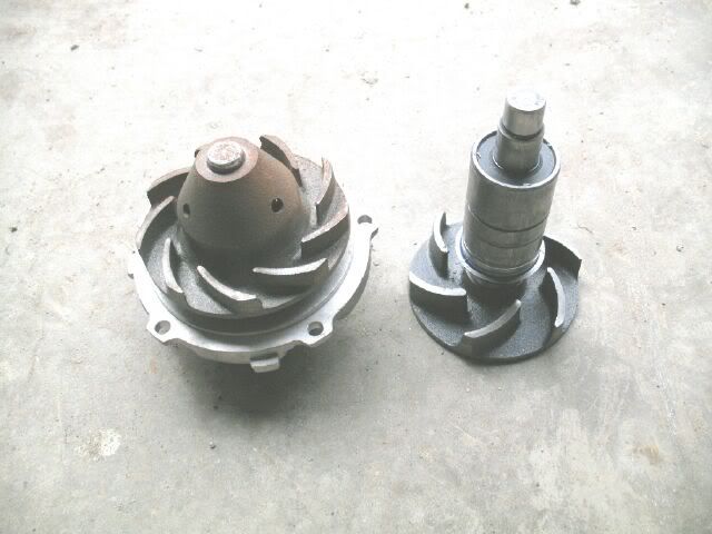
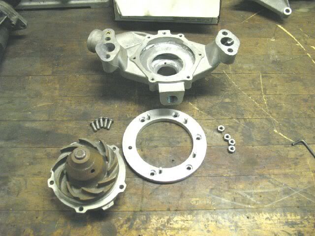
Start with an aluminum short style SBC water pump and tear it down completely. The only needed part is the bare housing.
A FWD 3.1 V6 water pump insert will become the mechanics for the new water pump. Here is a side by side of the removed SBC internals and the 3.1 pump insert.
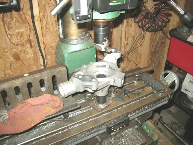
The large opening of the SBC housing is just slightly too small for the 3.1 impeller to fit, so just a small amount of the non-circular outer lip needs to be milled down.
Inside the SBC housing, the original impeller surface was tapered to match the tapered impeller. The new impeller is flat, so the tapered portion of the casting needs to be milled flat to the proper depth.
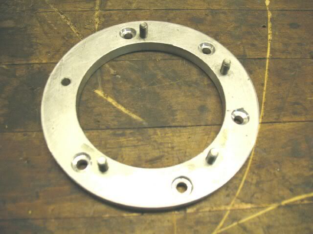
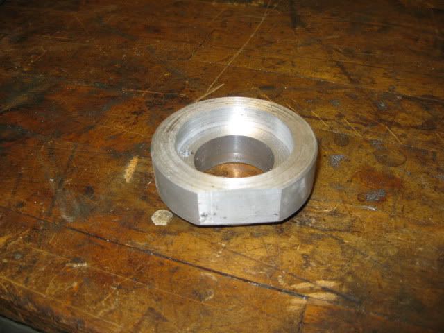
A 3/8” aluminum ring is fabricated as an adapter plate to go from the 6 bolt pattern on the SBC housing to the 5 bolt pattern on the pump insert and is also the needed spacer to properly position the 3.1 impeller.
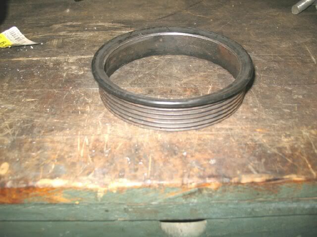
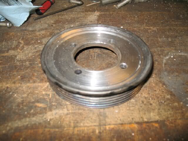
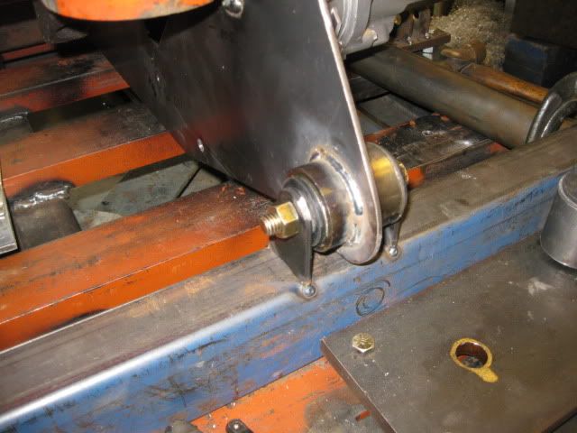
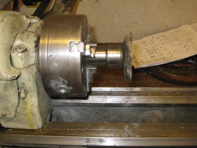
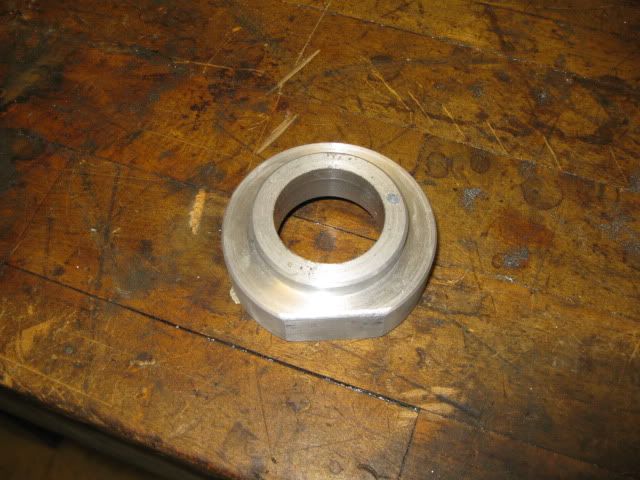
A serpentine pulley from some unknown application was used, but the 88 2.5 water pump pulley could also be used. The flange for the pulley was tuned off leaving just a small lip at the outer edge for the new flange to rest against.
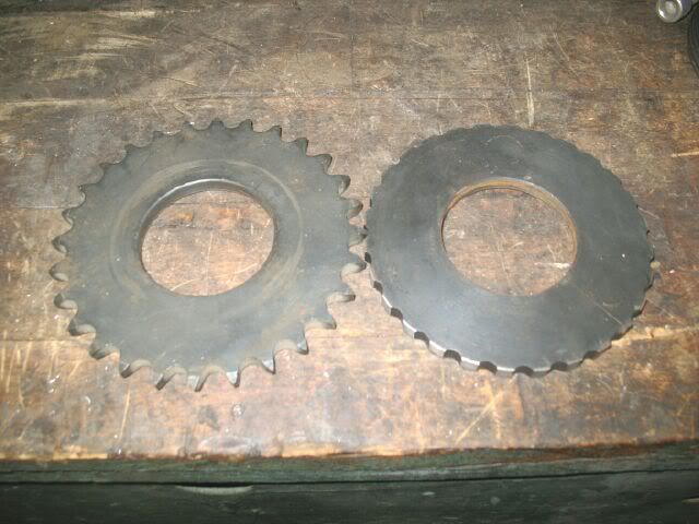
A sprocket with a 2” bore was used to make the new flange for the pulley since it had the right bore and was the right thickness to properly position the pulley close to the water pump. Here is a stock sprocket and a turned down one side by side:
Here the sprocket is turned down and sitting inside the pulley on the pump.
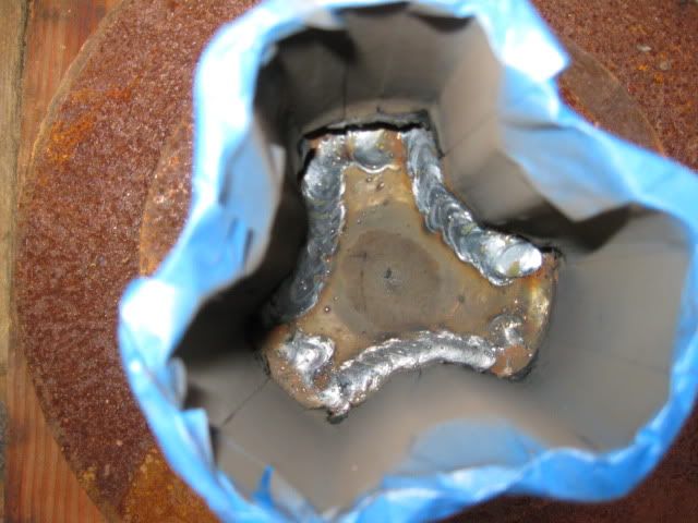
Then the sprocket was welded to the flange and the welded area turned down for a nice finish.
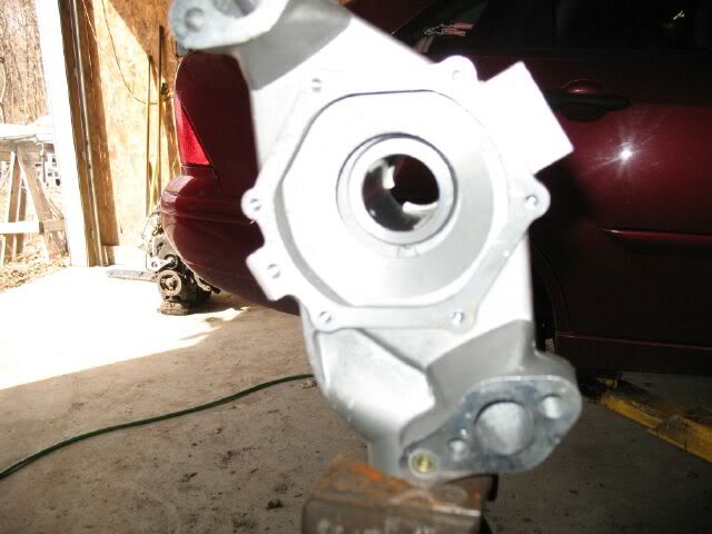
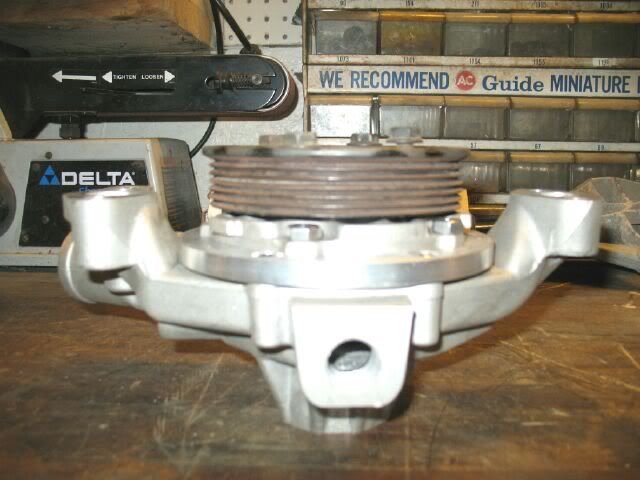
The snout on the SBC housing is then cut off to the gusseted are just to make it shorter.
Here is the final disassembled pics: Back together again:
Here are some pockup offset housiings - 2" thick:
[This message has been edited by fieroguru (edited 08-16-2009).]
IP: Logged
12:53 PM
fieroguru Member
Posts: 12550 From: Champaign, IL Registered: Aug 2003
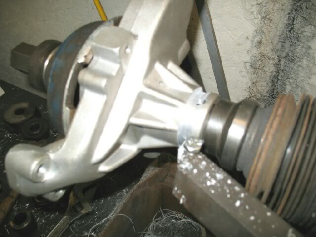
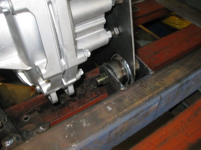
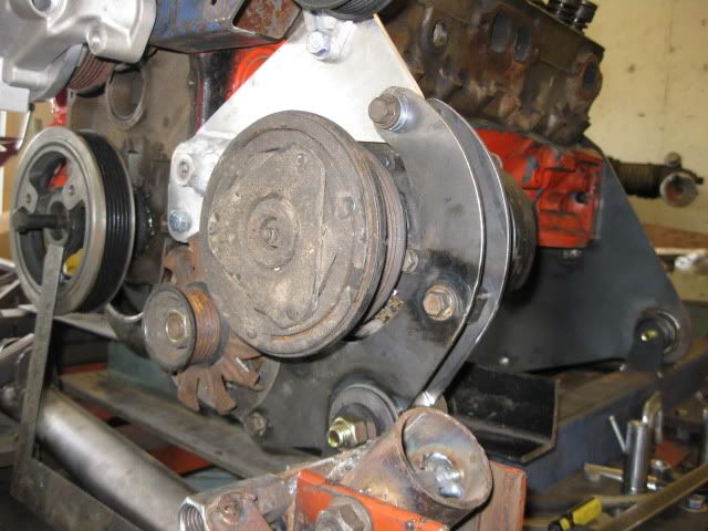
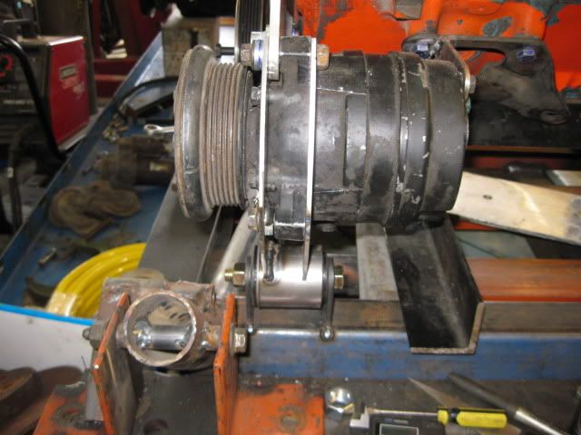
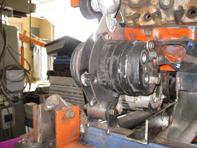
Harmonic Balancer and AC/Alt and Accessory Drive Bracket Fabrication The overall accessory drive will be very similar to the one fabricated for my 4.3 and will use stock 88 4 cly AC and Alternators. It already is a serpentine setup and I left room for the custom water pump to work with its belt routing.
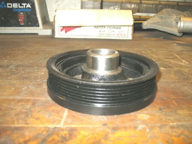
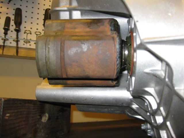
The harmonic balancer started life as a stock 3.1 balancer. You can get these brand new off Ebay for about $10+shipping.
Here is a bone stock 3.1 balancer.
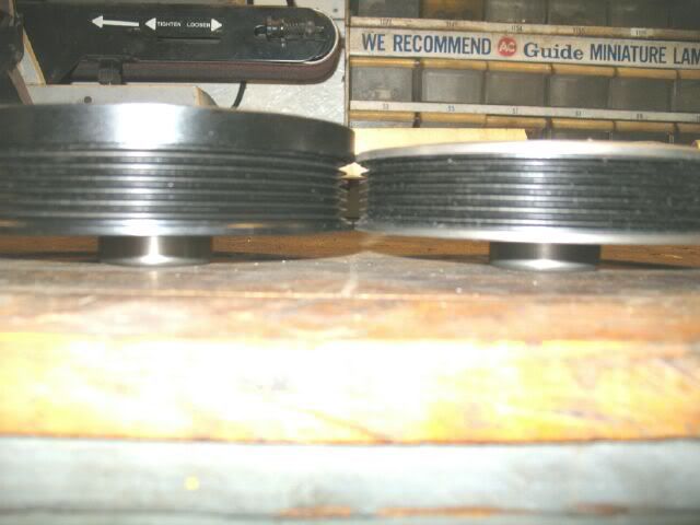
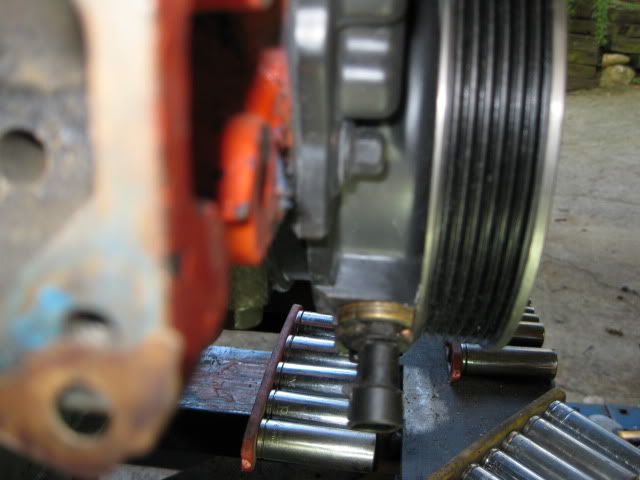
Here is a shot of the diameter difference between the water pump pulley (top) and the balancer. This will have the water pump running slightly faster than 1:1.
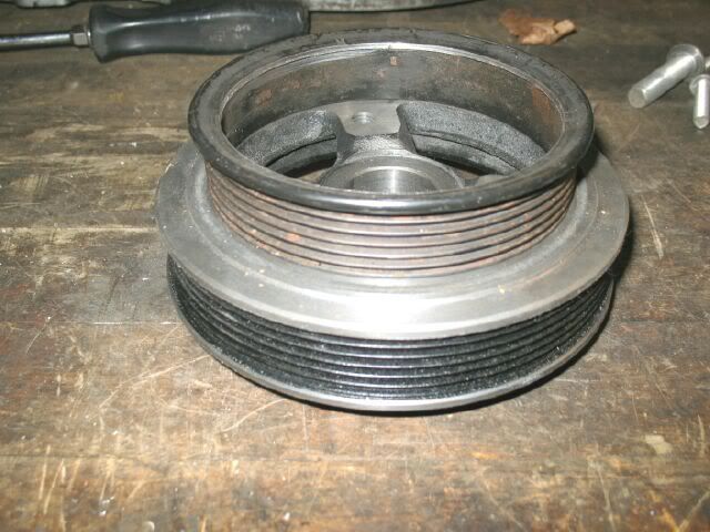
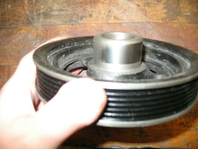
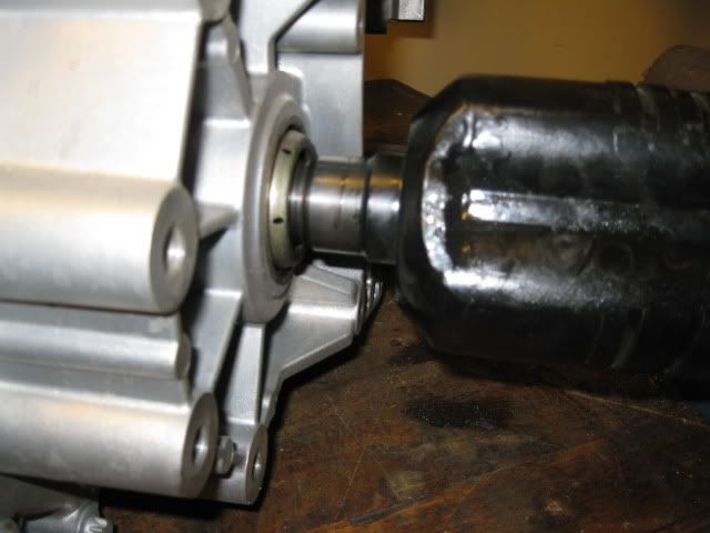
To make the balancer as thin as possible, the face had about ¼” turned off:
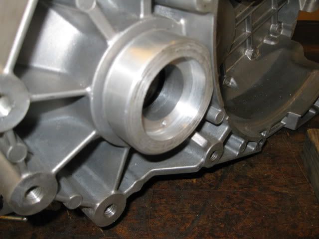
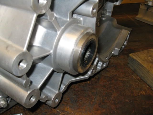
The seal surface for the crank seal was also turned further in on the back side, this will allow it to be mounted up tight against the timing cover:
Here is the balancer installed with the plastic vortec timing cover. I clearanced the backside of the balancer and trimmed the flange on the crankshaft sensor so the balancer could be tight to the engine and allow the offset housings to be 2" thick (stock tube thickness makes them easier to fabricate)
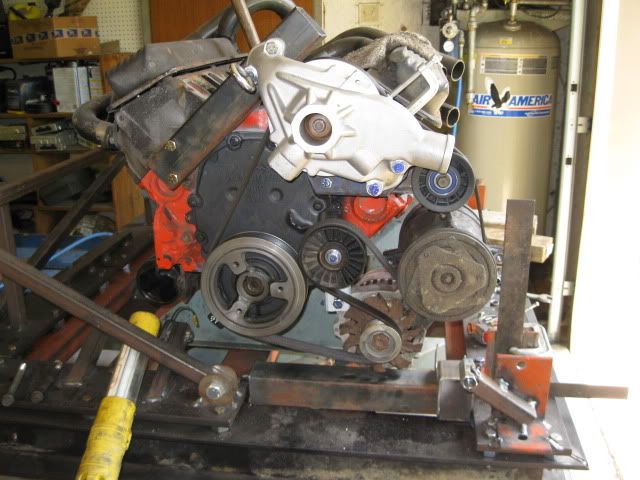
Here is a rough mockup of the accessory drive:
[This message has been edited by fieroguru (edited 08-16-2009).]
IP: Logged
12:54 PM
fieroguru Member
Posts: 12550 From: Champaign, IL Registered: Aug 2003
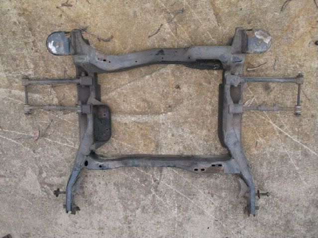
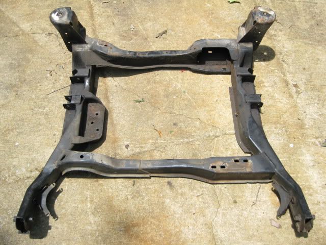
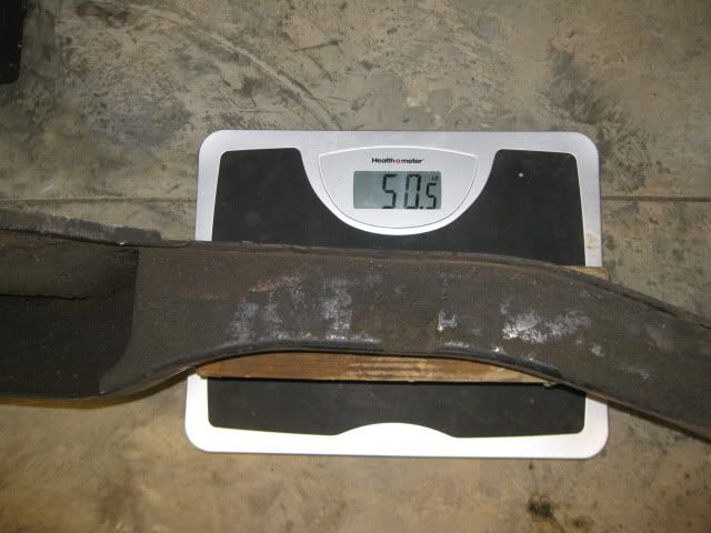
Here is a stock 88 cradle with all the bolts and links removed. It weighs 50 lbs as pictured, so opportunities for weight reduction are limited - maybe 10 lbs would be possible, but the tubular cradle is not being done for weight reduction (though it might weight less), it is more to move things around a bit for clearances.
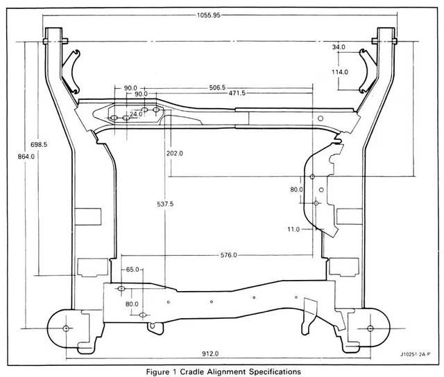
Here is the factory service manual dimensions:
The front crossmember will be moved several inches forward (up by the trailing link bolt) to spread the distance between the mounts.
The rear crossmember will be moved forward and as tight to the F40 diff as practical to free up as much space as possible for exhaust between the engine, crossmember and the trunk.
The side rails of the cradle and crossmembers will be 1/2” lower than stock and moved further out on the sides (will be under the lateral link pickups) to allow the drive train to be mounted ¼” lower than current (which is already lower than most) and provide clearance to the F40 diff.
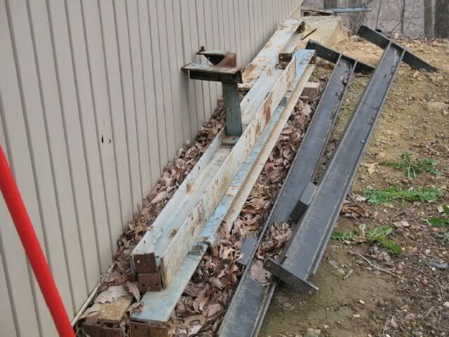
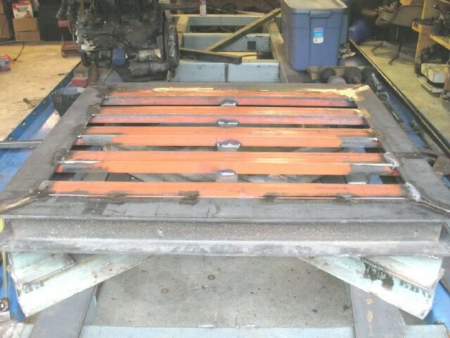
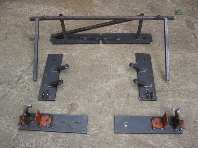
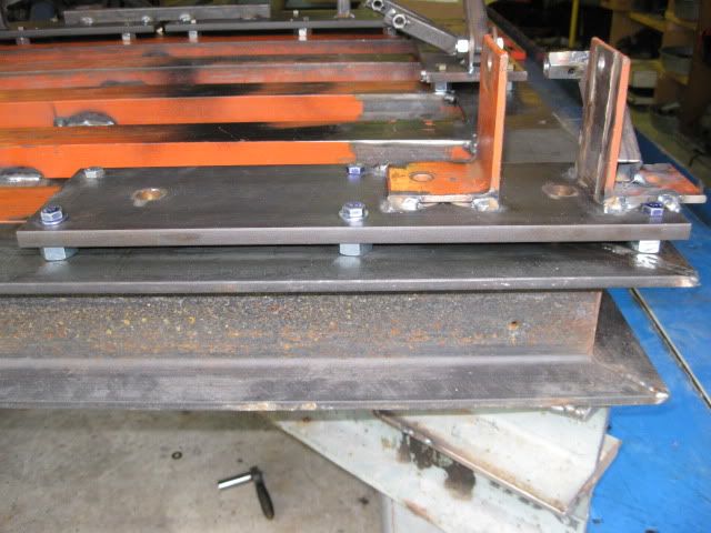
The cradle jig was made from 4x4x1/4” I-beam, 3" channel, 1/2" plate, scrap angle and 1x1 tube that I have collected over the years:
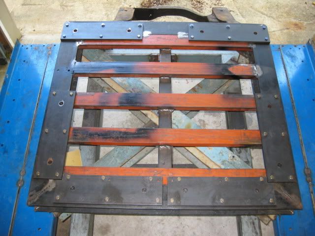
With all the bolt-on steel plates so everything from the cradle jig can be removed (and the base used again for something else):
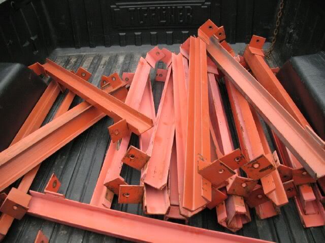
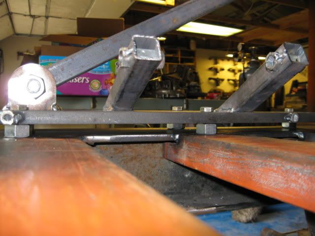
With all the brackets, tubing and braces for all the cradle mounts and suspension locations:
Here are all the individual plates and associated brackets:
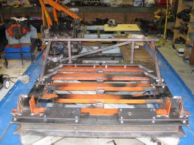
Here it back on the base raised 1/2" (to lower the base of the frame rails):
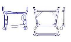
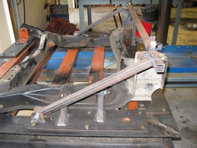
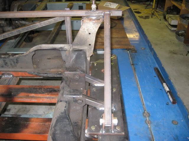
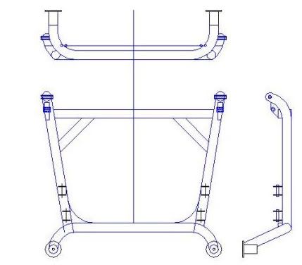
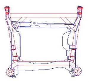
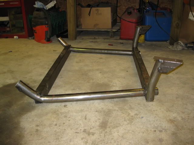
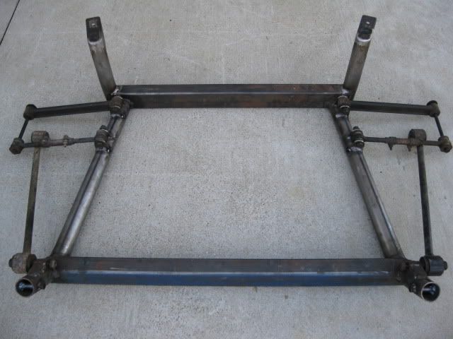
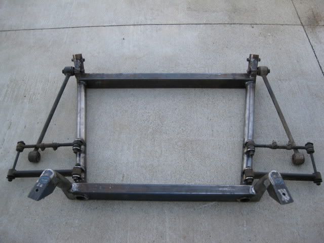
Here is the current new cradle design:
Here is an overlay of the new design in red and the stock 88 (copied image from service manual - notice it is not perfectly square):
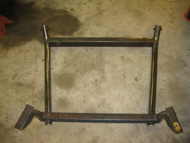
Since my pipe bender can not bend smooth 90 degree bends and I could not find a local place that could either, I went ahead and made the rear crossmember act as the connecting link between the main rails and the rear uprights:
Just need to clean up some of the welds, but the cradle is just about done. Once I have the engine/tranny mounts completed, I may add a couple of gussets/corner braces.
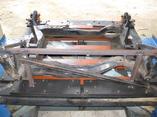
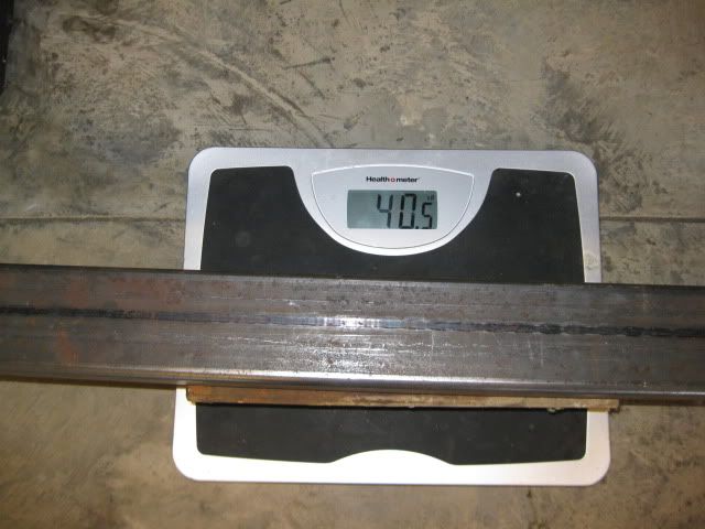
The bare cradle w/o any suspension links is 40.5 lbs and the stock 88 bare cradle is 50.5... so it is still 10 lbs less than stock (20% reduction).
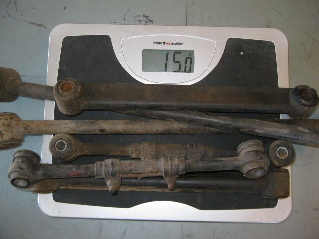
For grins, I weighed all the 88 rear suspension links - total w/o bolts is 15 lbs.
[This message has been edited by fieroguru (edited 10-11-2009).]
IP: Logged
12:55 PM
fieroguru Member
Posts: 12550 From: Champaign, IL Registered: Aug 2003
Engine & Transmission Rubber Mounts The engine and tranny mounts will be round rubber bushings. One of these ends will be welded into the outer edges of the adapter plate and ears mounted to the cradle crossmembers for to complete the mounts. The engine mounts will be incorporated into the intermediate shaft bearing support and the accessory drive bracket and again will attach with ears on the front crossmembers.
These 4 circular rubber mounts should keep engine/tranny movement to a minimum and eliminate any need for a dogbone or torque rod.
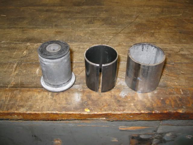
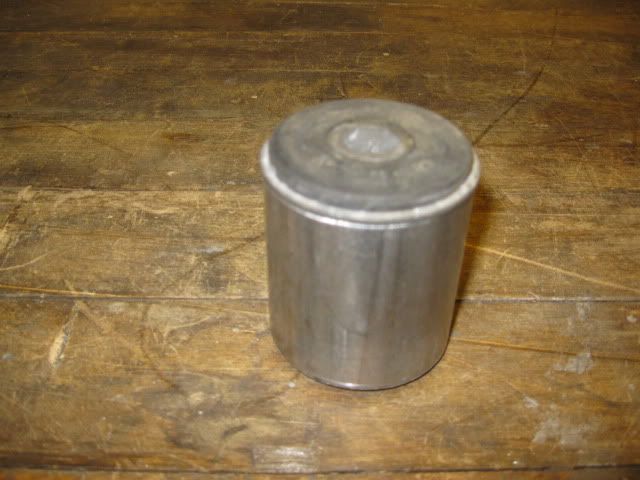
To keep the cost of the mounts down, I wanted to find an OEM suspension arm bushing that would work. Autozone part # FB235 was a good fit for this application and only costs $5.99 each. A small length of 16ga 1 3/4" exhaust tubing is the needed shim for the bushing to fit snug inside the 2" cradle tubing. The 1 3/4" tubing needed to be slit to fit over the bushing and this opening provided additional clearance to the welded seam on the 2" tubing.
The shim slid over the bushing and then the bushing was pressed into the 2" OD tubing. To get it the last 1/4" in, I had to break out the mini sledge... so it is a fairly snug fit.
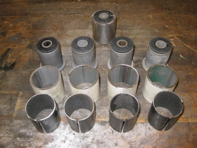
Here are all the tubing, sleeves and bushings needed for the engine/tranny mounts:
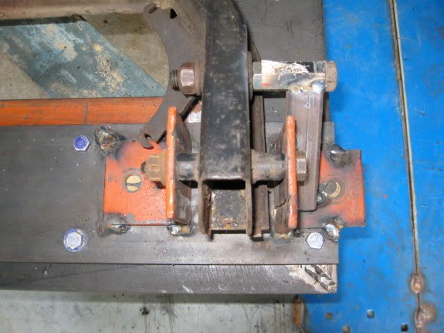
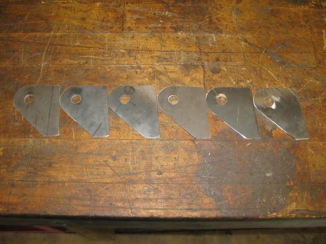
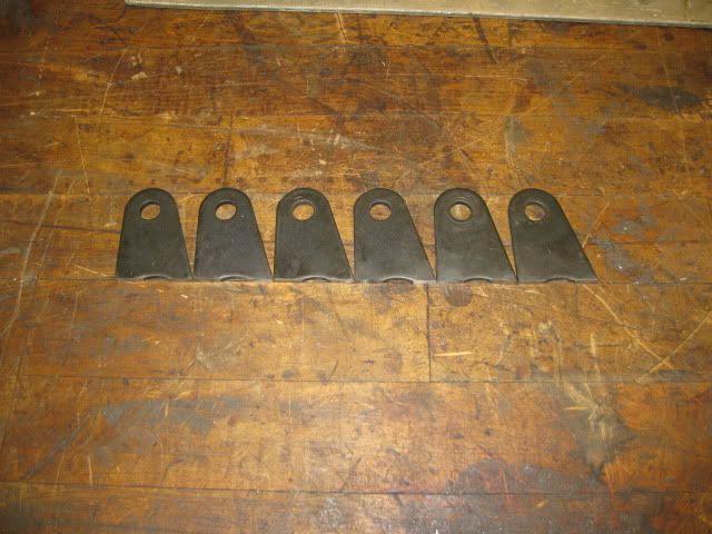
Here are the brackets for the rear mounts (fit on the front side of the rear crossmember) made from the same material as the adapter plate:
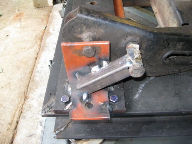
Here are the front brackets that will rest on top of the front crossmember. These were made from the same weld on tabs used for the lateral links.
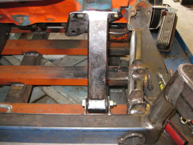
Tranny mounts brackets tacked in the proper location:
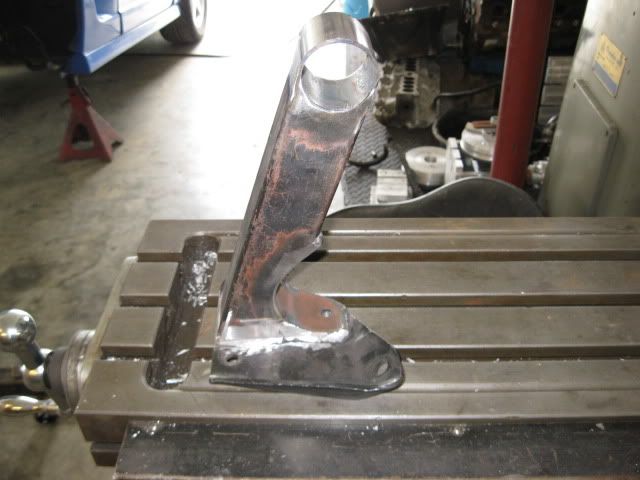
Front Engine bracket - made from the same material as the adapter plate and ties into 3 AC compressor bolts, one Alternator bolt and the upper aluminum bracket. Welding in the bushing sleeve...
Mockup with the bracket bolted together:
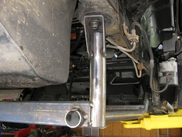
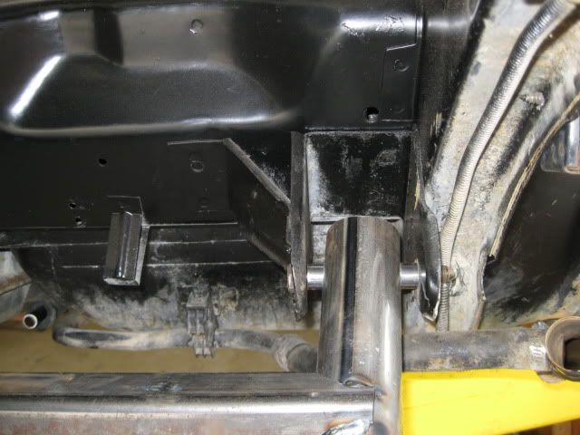
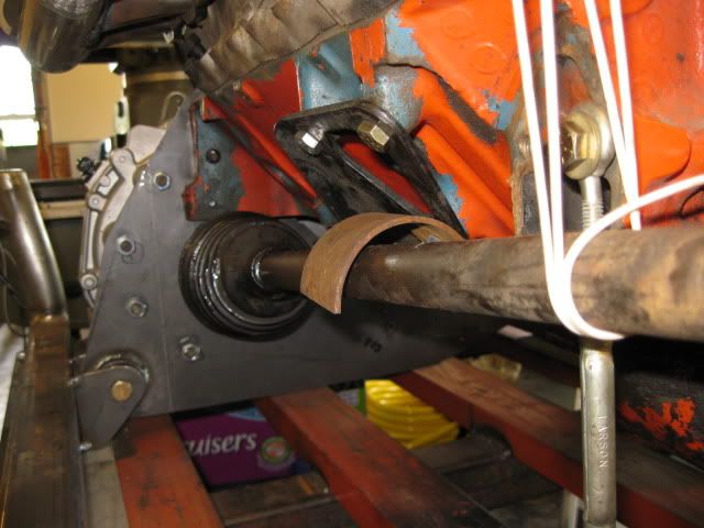
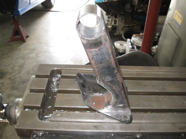
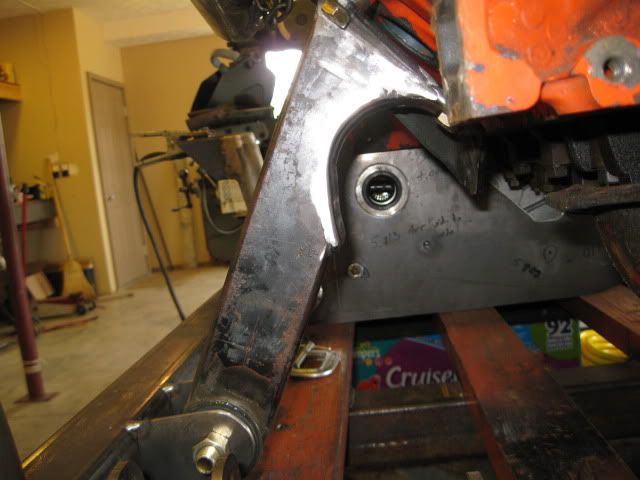
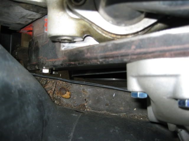
The rear engine mount had to clear the axle articulation, so during a test fit in the bay, the passenger axle was wired up into the location of maximum suspension compression for reference. Then took a piece of tubing to get the general clearance around the axle in this location:
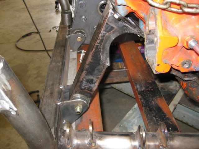
Then I took some 2x2x1/8" tube and made the rear mount that welded to the original engine mount bracket on the engine.
[This message has been edited by fieroguru (edited 05-11-2010).]
IP: Logged
12:56 PM
fieroguru Member
Posts: 12550 From: Champaign, IL Registered: Aug 2003
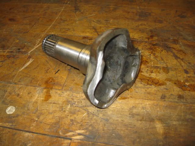
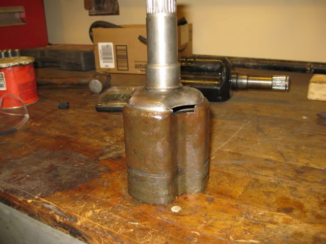
The tripods spline for the F40 is 27 and there are several sources of tripods that will fit the F40 transmission: G6/F40 stock axles Cobalt/Redline Supercharged 5 speed axles 1999 Saab 9-5 GM 5 speed autos (Torrent, Equinox, Aura, etc...)
For my first set of axles, I will be using hybrid tripods and factory GM axles. Essentially taking 2 tripods, and using the F40 compatible spline part with fiero and corsica style tripod cages and welding them together.
The passenger side will be using a 96 Corsica axle (Passenger side, 4speed auto). It has fiero compatible outer CV, the shortest GM axle shaft, and the same axle shaft splines as the maual fiero. The corsica rollers are different than the fiero, so I will use the Corsica roller cage. For the splined part for the transmission, I will use an OEM torrent tripod.
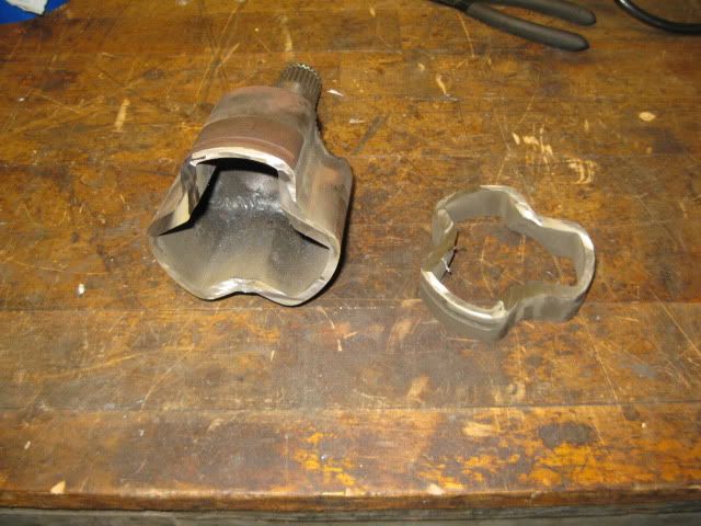
With the help of a 4 1/2" cut off wheel and a hand held grinder, I quickly rough cut the tripod housing off the Torrent shaft portion:
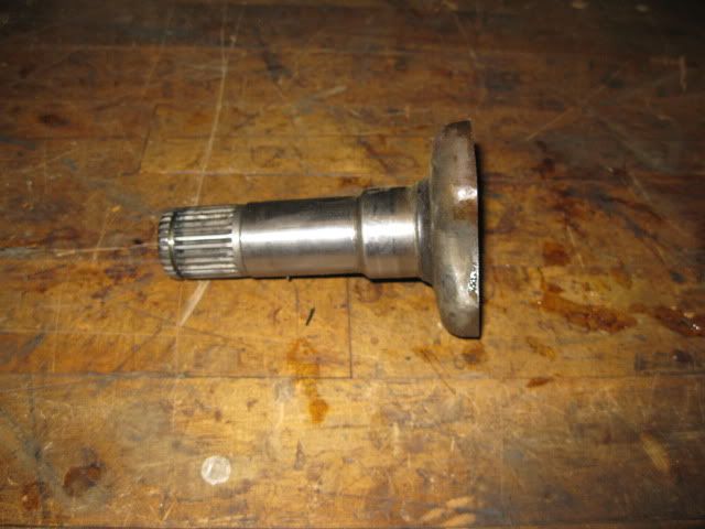
Then with a flapper disk on the grinder, I took off the excess material then chucked it in the lathe to finish the machine work.
Next the shaft portion was cut off the Corsica tripod housing, then put in the lathe to remove all the needed material to slide the 2 parts together.
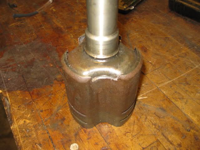
Test fit to check how much more material to remove off the shaft end:
Just needs welding inside and out:
This is what I was after, a shorter hybrid tripod so the 96 corsica axle shaft will work on the driver side.
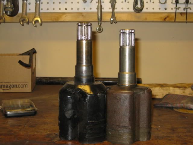
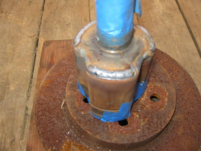
Wrapped the machined surfaces with some tape and fired up the welder...
Corsica/Torrent on driver side:
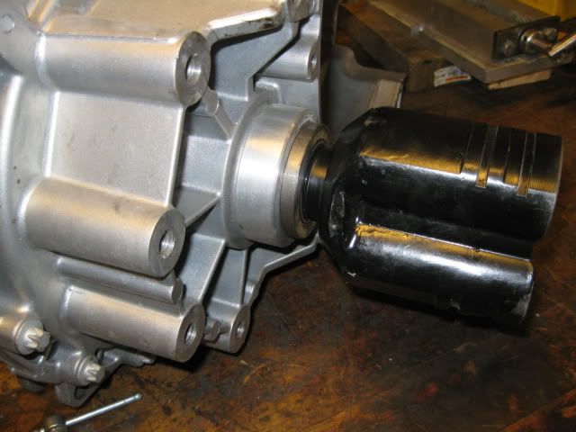
On the passenger side, I want to reuse the stock passenger fiero manual axle. A hybrid tripod between a stock fiero and Saab 9-5 yielded a hybrid tripod that was 1/2" longer than the Corsica/Torrent. This helps make up for the differential being offset to the driver side about 1":
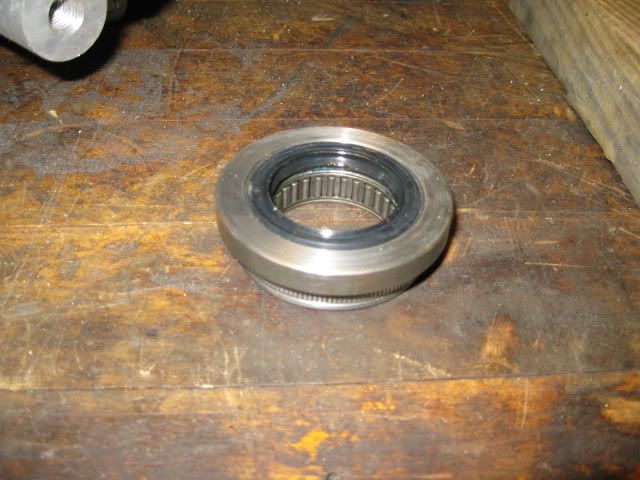
To support the tripod further out and to provide a means to seal it, I made a pressed in bearing housing to use one of the fiero axle stabilizer bearings.
Here is the axle stabilizer bearing (same for all manual tranny fieros).
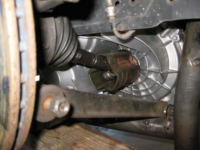
Upon test fitting the DS corsica axle, I noticed the tripod cage was too long and not allowing full axle articulation.
To fix this issue, I cut the outer set of CV boot grooves off and will use the inside ones instead (boot only uses 1 set).
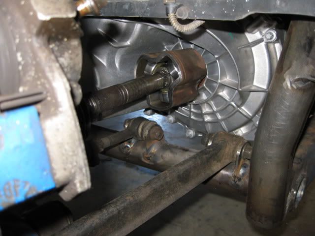
Driver Side Corsica Axle Clearance with Modified Torrent/Corsia tripod: While the lateral links were level and the axle nut removed, you can push the axle shaft through the hub so it becomes fully bottomed in the tripod cage. On the driver side the distance from the outer cage face and the outer surface of the tripod roller was 1 1/16". Once the axle nut was installed and the axle fully seated in the wheel bearing, the distance became 1/2, which is just about dead center of the shortened length of the tripod cage.
Passenger Side Fiero Manual Axle Clearance with Modified Saab 9-5/Fiero tripod Same setup and the fully compressed distance was 2 3/8 and the tighented axle nut resulted in 1 1/16, again just about centered.
This is how I measured the outer cage face to the outer edge of the roller:
These axles and hybrid tripods have the tripod rollers within 1/16" of being centered on each side with the current placement of the engine/tranny. Which also has about 3/16 to 1/4" of clearance between both frame rails and the tranny/balancer.
[This message has been edited by fieroguru (edited 05-11-2010).]
IP: Logged
12:57 PM
fieroguru Member
Posts: 12550 From: Champaign, IL Registered: Aug 2003
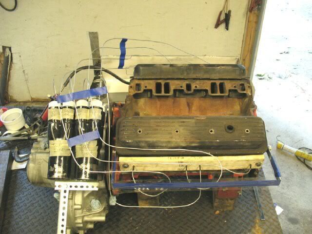
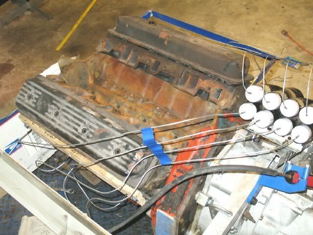
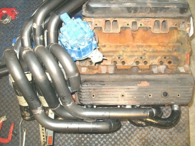
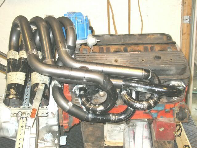
180 Degree Equal-length Headers I had started to built 180 degree headers for my current setup and put them on hold until the F40 swap was completed… Want to make sure the collectors are properly positioned to clear the shifter assy on the F40 which is much larger than the Getrag. Also, need to make sure the headers clear the Vortec crab dist.
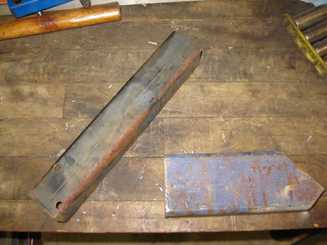
The headers will be a stepped tube design with 1 5/8” primary diameter for the first 12” and then 1 ¾” for the last 30” to the collectors. This will enhance low end torque and not be a restriction to high rpm power. All tubing will be 16ga for increased durability.
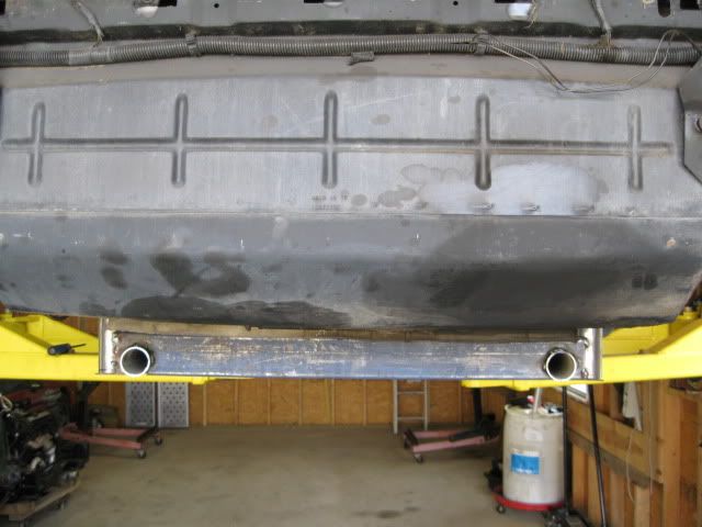
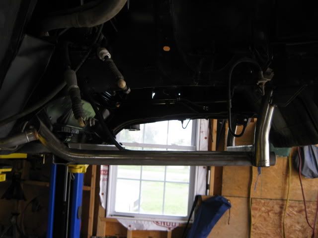
The collectors will rest above the tranny diff, dump to the rear of the car, go under the shelf of the trunk. From the collectors, dual 3” exhaust will be routed between the trunk and the engine and most likely will have 2 mufflers in series per side to help keep the exhaust note low enough for daily driving.
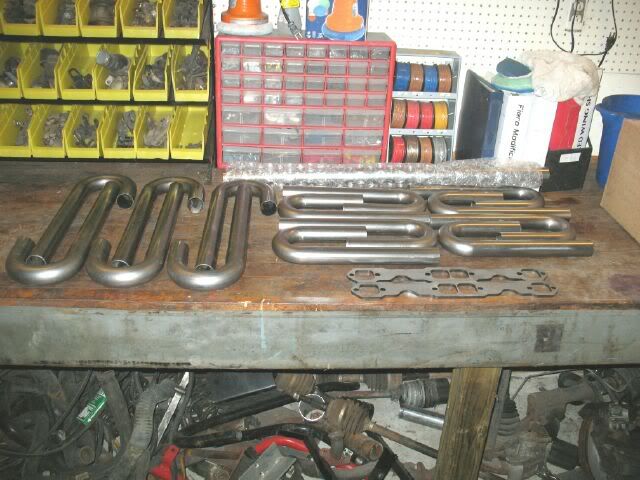
This portion can not begin until the adapter plate, engine mounts and cradle are complete, but here are the parts for the headers:
[This message has been edited by fieroguru (edited 04-10-2009).]
IP: Logged
12:58 PM
fieroguru Member
Posts: 12550 From: Champaign, IL Registered: Aug 2003
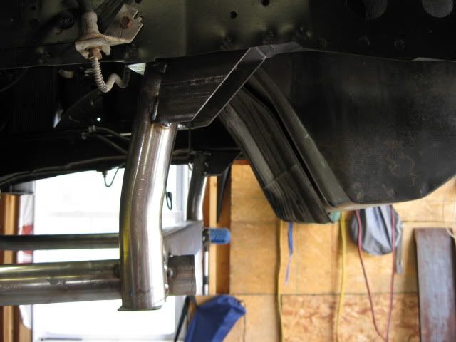
Engine Bay Modifications I plan to get rid of the stock hinge boxes on the firewall (thanks JefrySuko for the idea) and redo the current aluminum firewall (cut for the hinge boxes).
I might even do some panels on the driver side to clean it up some.
[This message has been edited by fieroguru (edited 04-10-2009).]
IP: Logged
12:59 PM
PFF
System Bot
fieroguru Member
Posts: 12550 From: Champaign, IL Registered: Aug 2003
Engine Wiring Harness/ECM As part of this upgrade, I will be switching from the 7730 ecm to the 411 LS1 ecm for true sequential efi, MAF for better part throttle drivability, and individual injector fuel trims (all the short runner intakes seem to need them).
This will require the installation of the Vortec timing cover, crank reluctor, crab dist, and coil.
All wires will be ran as hidden as possible with the ECM and MSD box being firewall mounted right next to the fuel filler tube. A small box panel will cover these items and help keep the bay clean – while reducing as much stuff from the center console as possible.
[This message has been edited by fieroguru (edited 04-10-2009).]
IP: Logged
01:01 PM
fieroguru Member
Posts: 12550 From: Champaign, IL Registered: Aug 2003
I'm looking forward to seeing how this build progresses. You have a lot of great ideas. You car is one of my favorite v8 Fieros out there. And I love how clean of an install you have.
I started this thread to share my ideas, not to bash anyone so please let's keep this civil.
Archie's kits work well and he has had many happy customers (myself included).
My design is a total failure in regards to being a kit... just too many required custom parts and these parts are needed to accomplish all the differences... but as a one off system solution is where I think it could shine.
quote
Originally posted by fieroguru: The Ground Rules: 8. I have no intention of selling SBC kits, but really enjoy the R&D and fabrication.
IP: Logged
08:14 PM
Formula88 Member
Posts: 53788 From: Raleigh NC Registered: Jan 2001
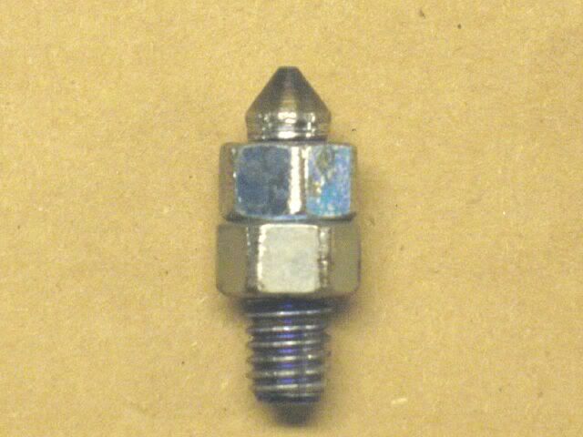
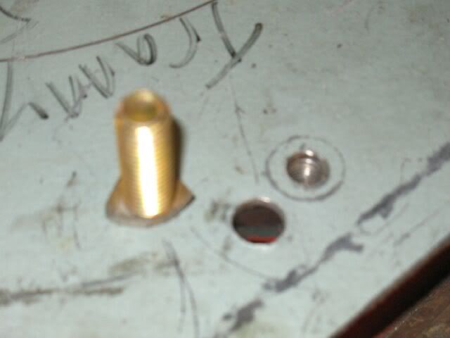
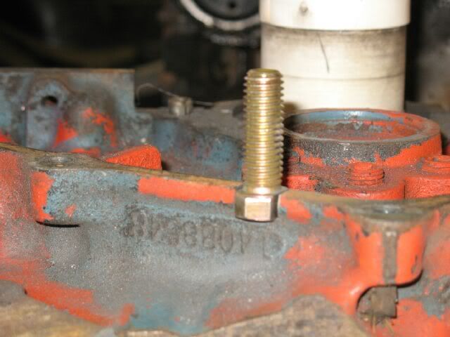
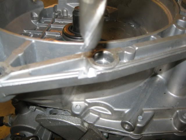
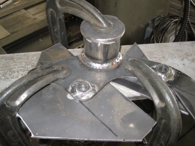
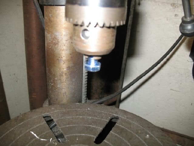
Just as an aside for people wanting to transfer bolt patterns from threaded holes.
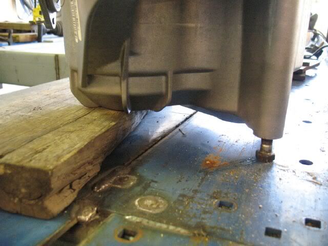
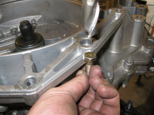
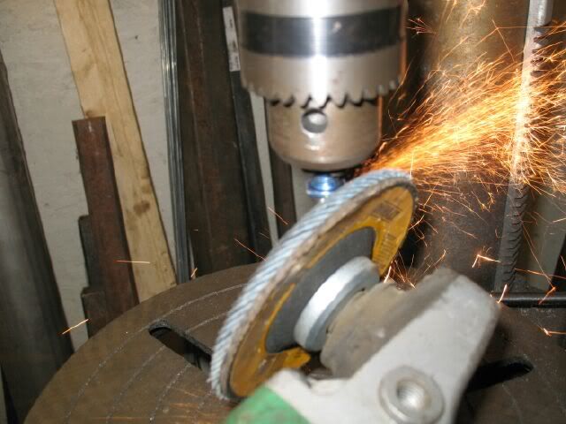
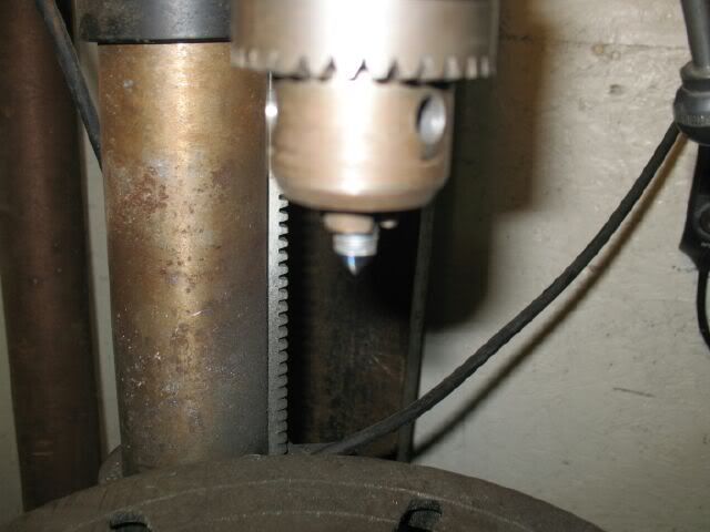
Just take a short bolt that fits the hole (3/4" long is plenty), then gently chuck the threaded portion in a drill press, start the drill and then bring over a grinder with a flap disk and grind away After a less than a minute you will have a centered fine point:
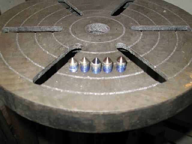
Repeat as needed for a set of threaded hole transfer punches:
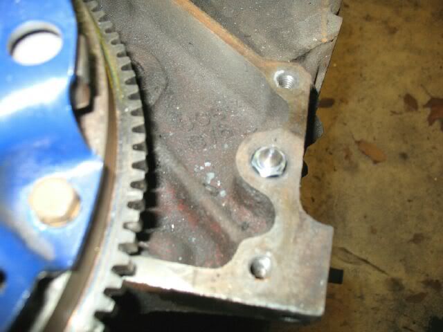
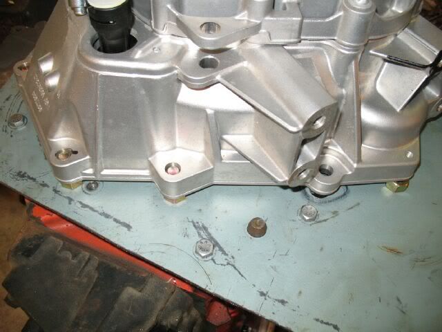
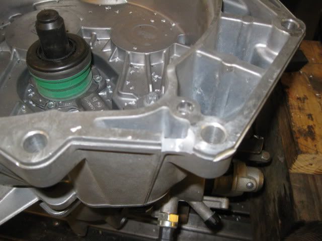
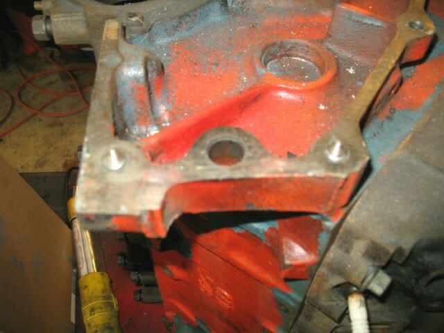
Install these center punches:
Position the plate and then strike directly on top of each one to mark the holes. Then drill them out (3/8" bit for a 3/8" bolt - best to keep them tight at this stage) and then lay the plate back in place over all the punches... if you did a good job then the plate just slips past all the bolts.
Just a simple trick that may come in handy...
IP: Logged
08:26 PM
Archie Member
Posts: 9436 From: Las Vegas, NV Registered: Dec 1999
It is so refreshing to see someone doin' instead of bitchin'.
I like you're waterpump.
A rear drive W/P is pretty creative. The next time you're at my shop remind me to show you this pump.......
One of my customers from the late 80's was an inventer & in 1990 or '91 he came up with this W/P for his V-8 car. I actually bought 5 of them from him & used them on a few of my cars. Serpentine belts in those days were relatively new & not as strong & durable as they are now. The only problem I had with them was they would shread a belt about 4 times a year. Replacing the belt required taking the pump off the engine to get it off & a new one on. I'd say in retrospect that the belt failures were most likely caused by belt quality & that today's better quality stronger belts would have lasted much longer.
They were pretty expensive to build & it turned out to be too hard to sell the kits when they had to use a $300.00+ custom waterpump. I know that a year or so later he said he sold the design to one of the 3 or 4 vendors back then that were selling V-8 kits for 914's.
I can't remember his last name right now & that was back before records were kept on PC's. Sometime I'll either remember his last name or I'll look it up in the archives.
Here are a few pics. Excuse the dust. you can see that sometime resently, I tried to sell it at a swap meet for $200.00
Keep up the good work.
Archie
IP: Logged
09:11 PM
fieroguru Member
Posts: 12550 From: Champaign, IL Registered: Aug 2003
That's a pretty cool pump there Archie! Was it setup to use the short to long water pump spacers to gain the needed belt clearance or something more custom? Any chance you have any pics with it installed or opened up to see the inside guts... just curious what solutions he came up with.
I missed the open house last year due to the birth of my 2nd girl, but maybe I can convince the wife she needs to visit her mom in Hinsdale about the time of FieroRama this year.
Please feel free to share any insights, concerns or other commentary.
IP: Logged
10:08 PM
PFF
System Bot
Archie Member
Posts: 9436 From: Las Vegas, NV Registered: Dec 1999
That's a pretty cool pump there Archie! Was it setup to use the short to long water pump spacers to gain the needed belt clearance or something more custom? Any chance you have any pics with it installed or opened up to see the inside guts... just curious what solutions he came up with.
I missed the open house last year due to the birth of my 2nd girl, but maybe I can convince the wife she needs to visit her mom in Hinsdale about the time of FieroRama this year.
Please feel free to share any insights, concerns or other commentary.
The original pump he did is the one I still have. the others were all made with Aluminium castings. Back in those days, everything I took pics of were on film. I didn't suspect that I'd still be doing this 16 or 18 years later & didn't take pictures of everything I laid hands on. If there are any pics, I'd have to go thru boxes of old pics to find them.
I never took one of them apart. As you can see the diameter of the pulley interferes with the AHCS's that hold the back cover on, so servicing it would be dificult because the pulley appears to have been sweat fitted on.
The pump was spaced out from the engine with 2 CNC machined Alum. fittings. I still have a set of them around somewhere.
Archie
IP: Logged
10:37 PM
Apr 11th, 2009
Isolde Member
Posts: 2504 From: North Logan, Utah, USA Registered: May 2008
You never cease to amaze me, figuratively speaking. While 1/8" may be perfect for the SBC, 1/4" would be better for the LSx. How much $ would you charge for a 1/4"-thick steel adapter plate, if you can make one? I'm getting frustrated with my own design. Yes, I could just run your 1/8" plus some washers, or 2 of the 1/8", but I'd much prefer a single 1/4". Thanks.
IP: Logged
02:52 PM
rcp builders Member
Posts: 736 From: north port, Fl. Registered: Apr 2007
Guru i love your ingenuity and ability to think outside the box and am looking forward to following this build. ARCHIE that is so funny you show that water pump. I live in N.H and actually went to Laconia to look at a fiero back in 1989 or 1990 and the man told me it was a kit but that he had redesigned the water pump. I believe it was black ,305 with an auto done real clean like, you would have appreciated this man Guru. Any how didnt mean to side track thread, great job Guru. Ray
IP: Logged
04:02 PM
fieroguru Member
Posts: 12550 From: Champaign, IL Registered: Aug 2003
You never cease to amaze me, figuratively speaking. While 1/8" may be perfect for the SBC, 1/4" would be better for the LSx. How much $ would you charge for a 1/4"-thick steel adapter plate, if you can make one? I'm getting frustrated with my own design. Yes, I could just run your 1/8" plus some washers, or 2 of the 1/8", but I'd much prefer a single 1/4". Thanks.
All else being equal, the LSx plate would need to be thinner (or the flywheel thicker). The LSx crank flange is about 1/4" closer to the block than the SBC (LS4 is even closer still), so doing anything but pushing the flywheel further towards the tranny will cause less spline engagement and potential throwout bearing issues.
Russ Brown (the guy who helped me on the waterpump) has his own adapter plate design and uses a series of stacked 1/4" plates... if you were looking for a 1/4" adapter plate he might be able to be talked into making one for you.
I am loading up more pics so stay tuned.
IP: Logged
04:31 PM
Tony Kania Member
Posts: 20794 From: The Inland Northwest Registered: Dec 2008
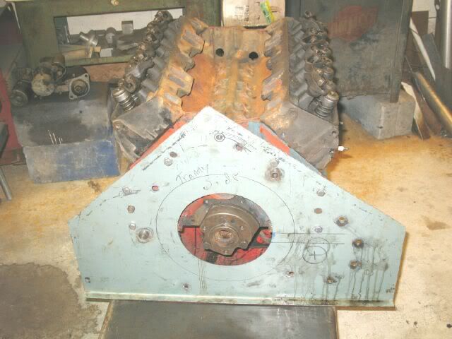
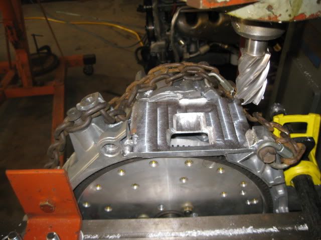
I needed to transfer the hole locations for the dowel pin locations on the engine to the plate, so I made this center punch from 3/8" bolt and nuts. Had to round off the points of the nuts to fit down into the block:
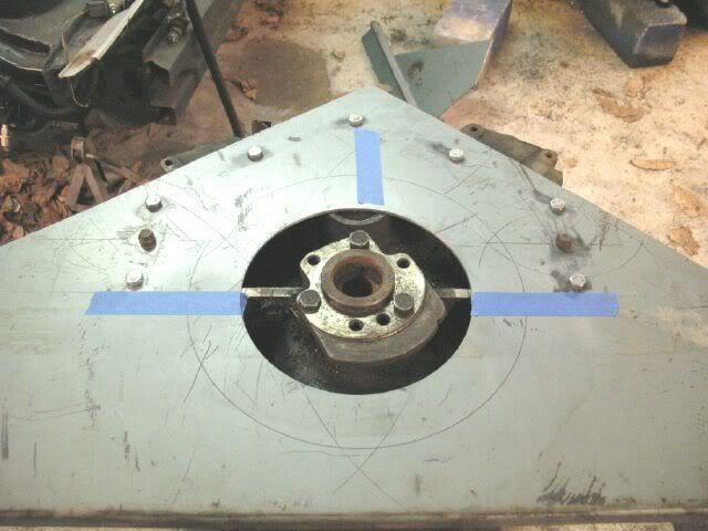
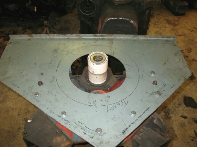
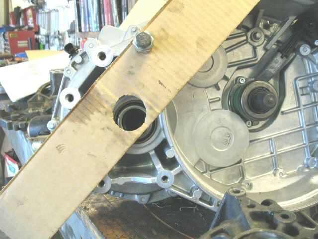
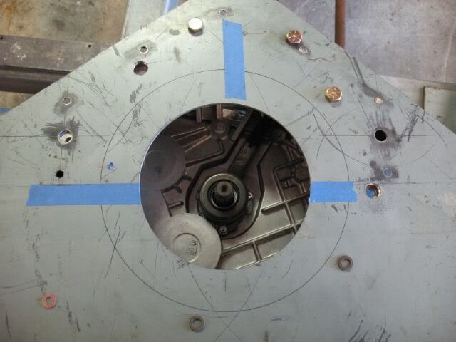
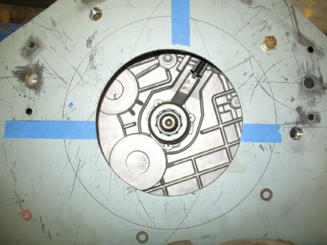
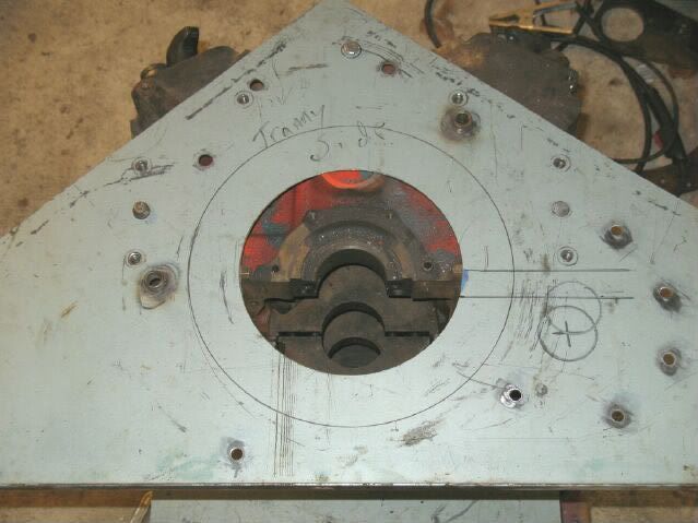
Once the dowel pin holes were done, it was time to move on and cut out the center hole for the crankshaft. I had measured it out and had to use a hole saw to get the 1st hole so I could put it on the lathe. The hole from the lathe is within .020" of center... but that is fine since it is just a hole.
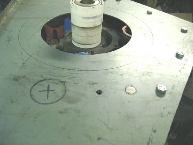
Then I took a spare flywheel and put one of the bolt hole centering tips in it and spun it around the plate. This gives me a true scribe line that can be used to ensure the tranny input shaft is properly centered to the engine crank.
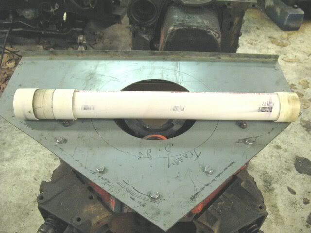
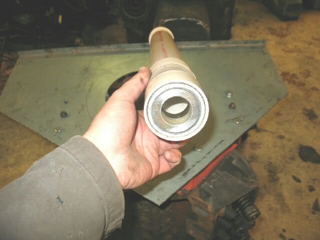
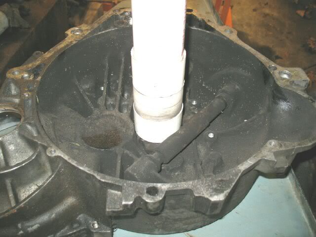
A few months back I made this input shaft centering tool. It is PVC pipe with some couplers glued over the pipe (had to cut the inner flange of the coupler out so they would slide over the pipe. One end had two 1 1/4" lock collars epoxied into place, then the OD of the sleeves were turned down on the lathe to fit into the SBC crank mains w/o bearings. The 1 1/4" lock collars fit tight to the Isuzu throwout bearing sleeve.
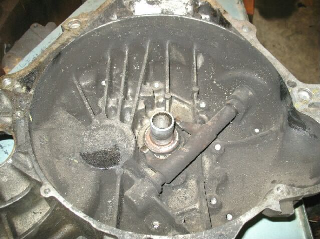
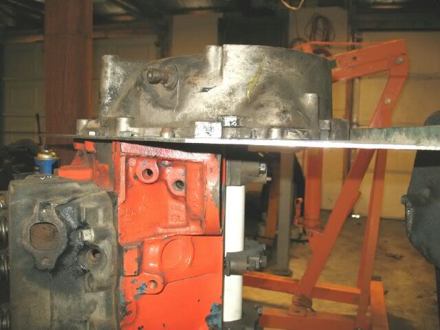
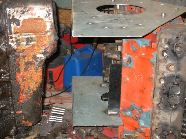
With the isuzu tranny sitting in place and centered to the crank, the output shaft location was marked (to be used as a guide as it is rotated up 1". You can also see I ground down the rear dowel pin flush with the plate so the tranny can cross over it.
Rotated up 1":
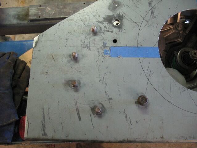
To make it easier to transfer the hole locations on the tranny, I drilled out the non-dowel pin holes to 5/8" and the dowel pin holes to 3/4". Then used the transfer punches and drilled the holes out to 1/2" and 3/4". I will be using 1/2" bolts as studs for the plate (stainless steel for the final version) and the holes for the dowel pins are slightly oversized (to allow proper positioning when I measure the tranny centerline to the scribed ring). Once the final placement of the dowels is determined I will tack weld them on the backside of the plate.
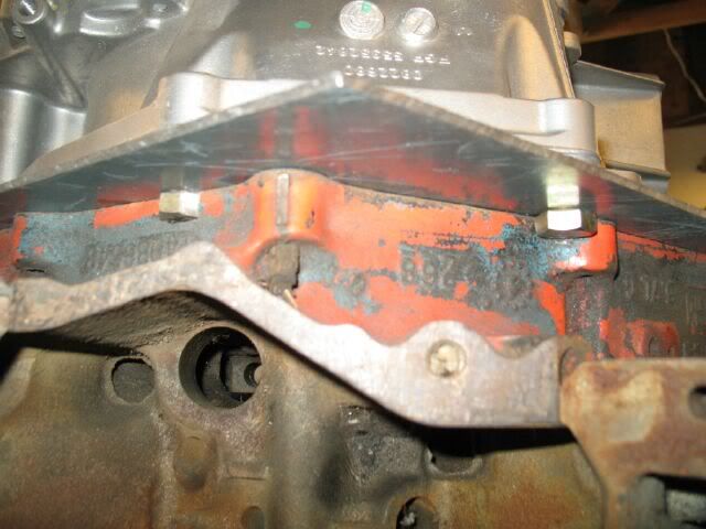
The top two tranny bolts/studs have some interferance to the bellhousing flange of the engine. The front side one the flange is right up against the bolt hole, so a portion of the bolt head had to be removed. The rear one is almost dead center to the flange, so the flange was clearanced and the bolt head ground down on the sides to fit in the slot cut in the bellhousing flange. These bolts will eventually be tacked in place on the backside of the plate (just held in place with nuts on the top side for now).
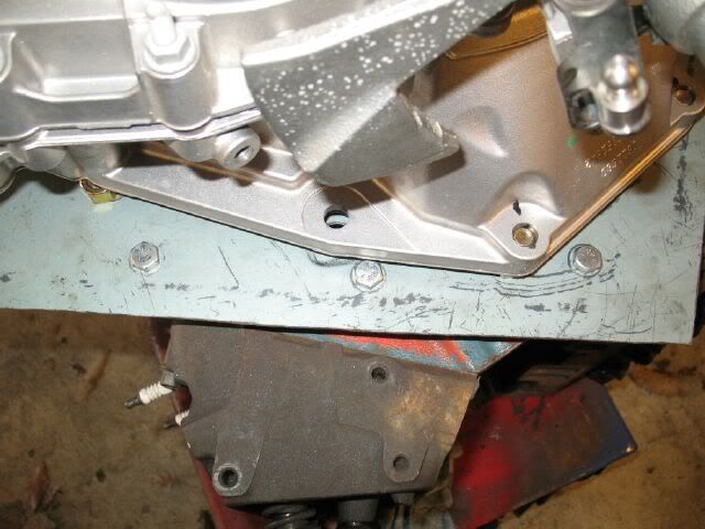
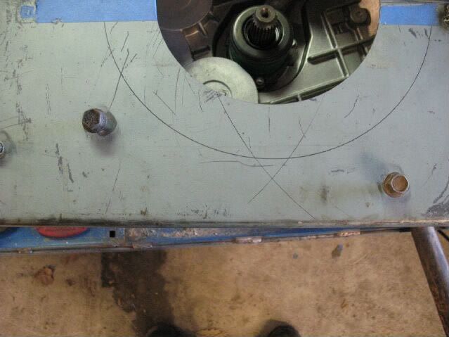
Two of the 3/8" bolts that hold the plate to the engine will interfere with the F40. I am planning to notch the tranny flange slightly to clear these two bolts.
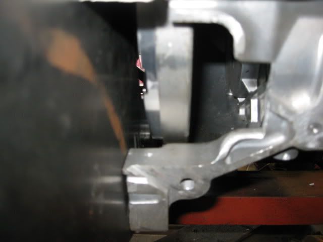
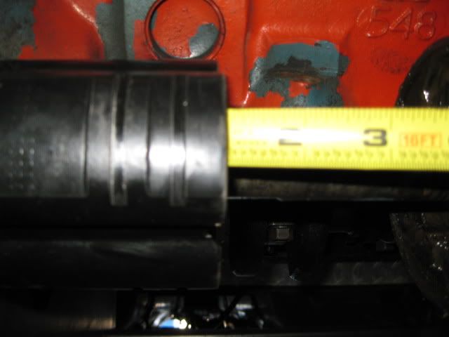
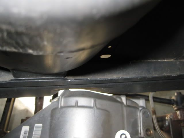
With the F40 having the offset diff, the bottom rear 3/8" bolt clears everthing even while being covered by the tranny:
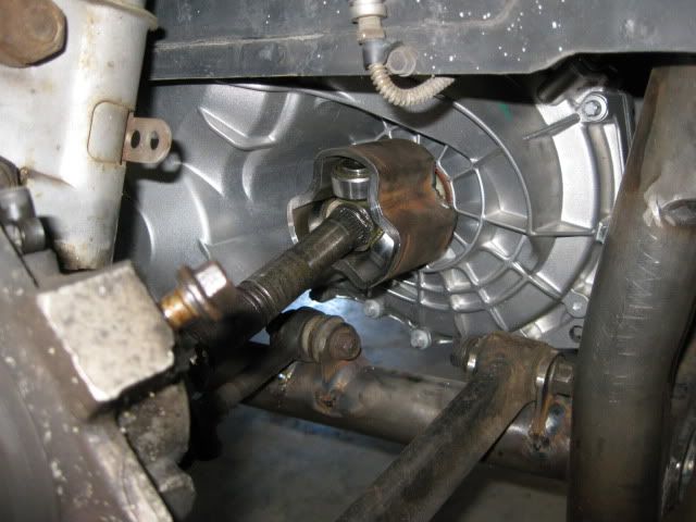
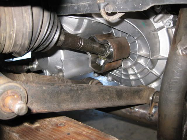
I haven't seen this discussed before, but the location of the F40 Axles is in a slightly different location that the Isuzu. Here is a cardboard template of the axle location from the isuzu and bolted up to the F40. The F40 acxle location is further down and to the front than the Isuzu.
IP: Logged
05:47 PM
fieroguru Member
Posts: 12550 From: Champaign, IL Registered: Aug 2003
You're correct, but, you didn't figure the flywheel issue into your LSx thinking. There are a few ways to go. Also, the truck LSx cranks have a longer tail. And any stroker crank, not that Fiero guys should be stroking an LSx with an F40, can be ordered with this longer back end. But because of the deep bellhousing, it's the better choice of crankshaft. Cheap, strong, and plentiful. I'm one of very few people attempting the LSx/F40 besides Archie, and the LS4 doesn't need any adapter plate, so any such plate has to be for all LSxes EXCEPT the LS4. I'm stopping here so I don't hijack your thread, and I thank you for the referral.
I love these threads where someone that really knows what the heck they are doing goes off on their own. I learn a lot from reading these threads...not that I could ever do it myself, but it's educational.
BTW, you will love the F40. The ratios don't look that good on paper, but fortunately we don't drive paper.
IP: Logged
11:31 AM
PFF
System Bot
fieroguru Member
Posts: 12550 From: Champaign, IL Registered: Aug 2003
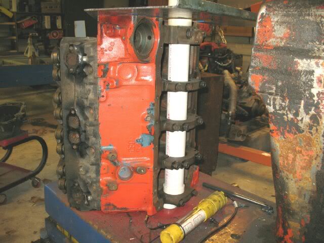
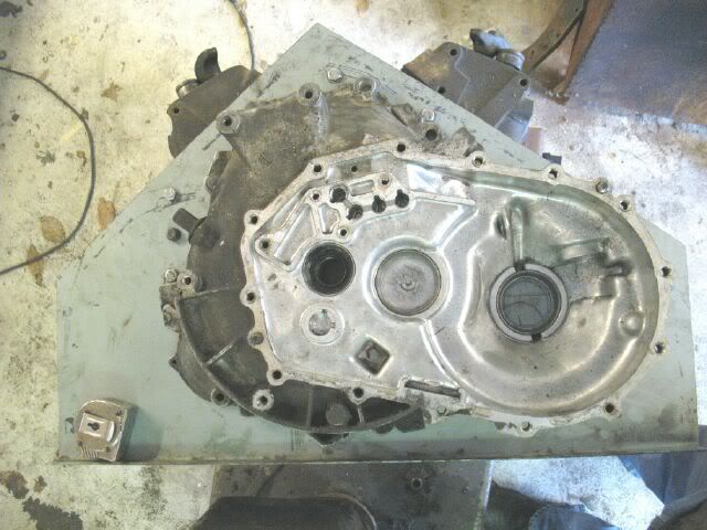
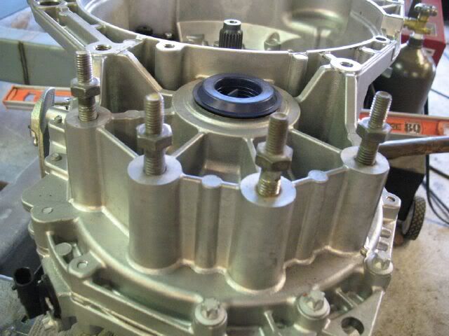
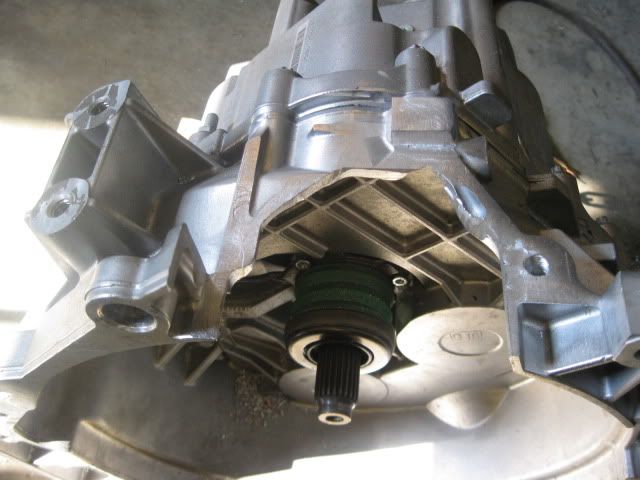
More adapter plate stuff... found the needed tranny dowel pins and set the F40 up on end;
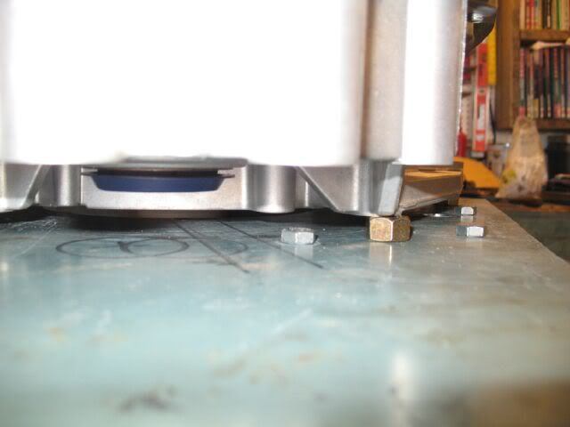
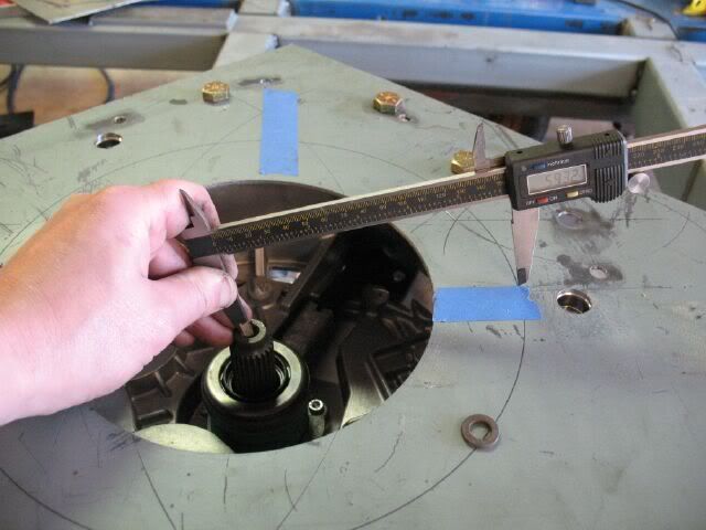
Then put a washer down the dowel pin hole to ensure the dowel pin will not bottom out in the tranny while being bolted up to the engine. Spend about 2 hrs using my calipers to get the plate centered on the input shaft of the F40 then clamped everything down tight and welded the dowel pins on the plate.
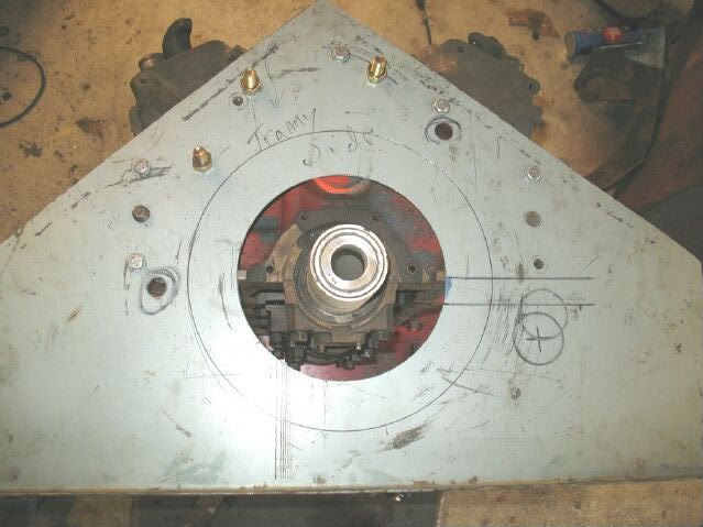
Once the dowel pins were located, then it was time to drill out the differential and lower tranny case holes. Made a couple more threaded center punches for these.
Repurposing the bellhousing bolts/studs (I rarely use them because they look bad), but still need to have some spacers made the right thickness.
The adapter plate is getting closer to being done.
Still need to: Drill axle hole Drill for mounts Finalize the final external shape of the adapter plate.
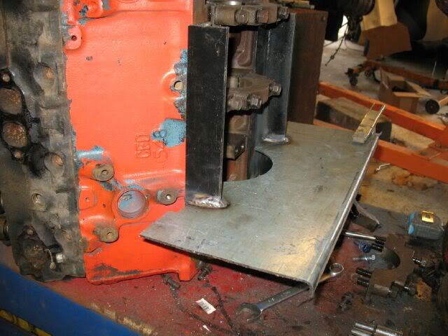
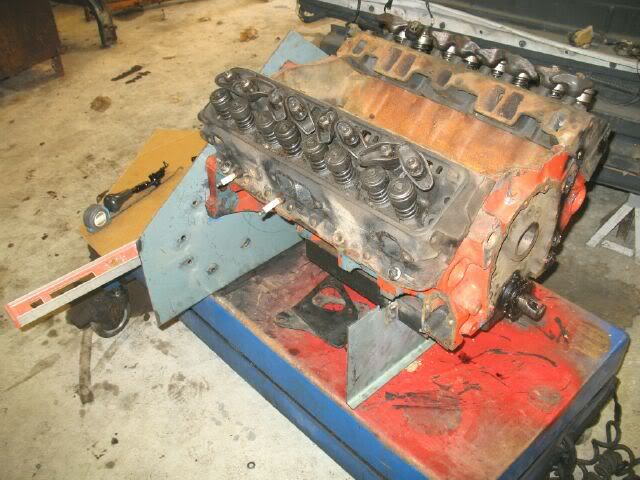
The mounts and final shape can not be done until the cradle is built, so it is time to get the engine right side up again.
The adapter plate will be used to hold the engine at the right elevation and level, so I need to make another plate for the front to support the engine.
Some time this week I will tear down the greasy engine (locked up) and steal the crank for the mock up engine, then the engine will be put back in its normal orientation.
[This message has been edited by fieroguru (edited 04-12-2009).]
IP: Logged
07:17 PM
fieroguru Member
Posts: 12550 From: Champaign, IL Registered: Aug 2003
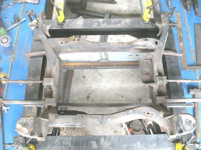
Here is the mock up cradle. It was the original cradle from the Red car that now has the 4.3. I am not planning on modifting anything on this cradle, just using it to build the fixture for cradle mount locations and suspension locations and nothing more...
Here is the 4x4 I beams that the main beams of the fixture will be made from:
And here is some C channel that will be used for crossmembers and other stuff:
Best part is all this scrap steel was FREE.
IP: Logged
08:03 PM
JPW Member
Posts: 87 From: Lexington, KY Registered: Nov 2008
Originally posted by JPW: Looks a lot warmer than when I was there. The work and craftsmanship is excellent, I think I may have to wander that way again in the near future. James
Yes, it is much warmer than the 30 degree day when you were last down here! Feel free to stop by whenever.
Spent some time today laying out the adapter plate in autocad with the rotated pattern.
I am planning on adding in the rest of the tranny holes and the final overall shape (once that is determined), then I can spend a few hrs at work and drill to numbers on the mill and used the shear to cut out the final shape. I added some machined slots to help with indicating everything in the future.
IP: Logged
03:51 PM
Apr 17th, 2009
fieroguru Member
Posts: 12550 From: Champaign, IL Registered: Aug 2003
Been doing some cradle stuff. I am planning to use 2" diameter tubes for the side rails and the rear hoop that will attach to the rear cradle mounts. The front crossmember will be 2x4 with tapered down ends to meet up with the 2" tubes and the rear one will have a 2x3 channel (cut from the 2x4 material) placed on top of the rear 2" tube to help stiffen it up. Still a ways to go, just trying to design it with the fewest bends while providing all the clearance needed.
IP: Logged
10:56 AM
Apr 18th, 2009
fieroguru Member
Posts: 12550 From: Champaign, IL Registered: Aug 2003
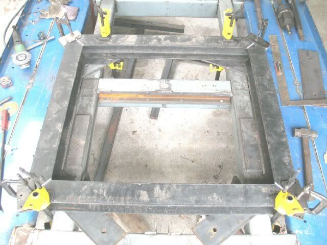
I got the greasy 307 tore down and it gave up its crank for the the cleaner mock up engine. This engine will never be built, so I went ahead and greased the mains so the crank can turn freely (also clearanced my front engine support bracket so the counter weights would clear it too).
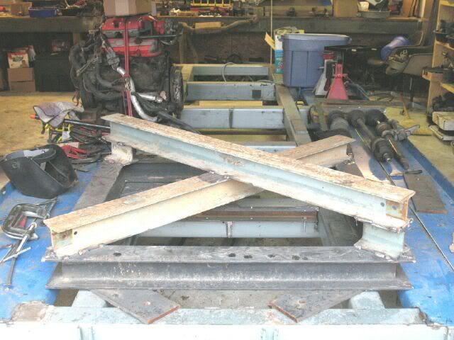
Then started cutting the steel for the cradle fixture. Still need to cut the crossmembers and remove the welded on angle from them, but this is what it is starting to look like.
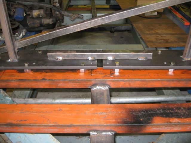
Here is the cradle sitting on it and spaced 1" up with some 1x1 stock. Once done, the cradle will be positioned 1" up from the platform and then all the suspension and cradle pickups will be setup. This will allow the new cradle to retain all the stock geometry while allow the main rails to be 1" lower than stock.
IP: Logged
06:12 PM
Apr 19th, 2009
vortecfiero Member
Posts: 996 From: Toronto Area, Canada Registered: Feb 2002
87 Fiero GT 5sp with Vortec L35 4300 Turbocharged V6 Bully Stage 2 clutch Syclone intake manifold and engine management with Moates adapter and chip burner Air/water intercooler and Devil's Own progressive water/alky injection 50lb injectors, 3 bar map sensor, Walboro fuel pump and Jabasco Intercooler pump LM1 wideband on custom manifolds and 3" stainless exhaust system T31/T04B H3 turbo and a S10 caliper conversion. Murphy's Constant Matter will be damaged in direct proportion to its value Murphy's Law of Thermodynamics Things get worse under pressure. Arthur C. Clarke "Any significantly advanced technology is indistinguishable from magic"
IP: Logged
10:11 AM
fieroguru Member
Posts: 12550 From: Champaign, IL Registered: Aug 2003
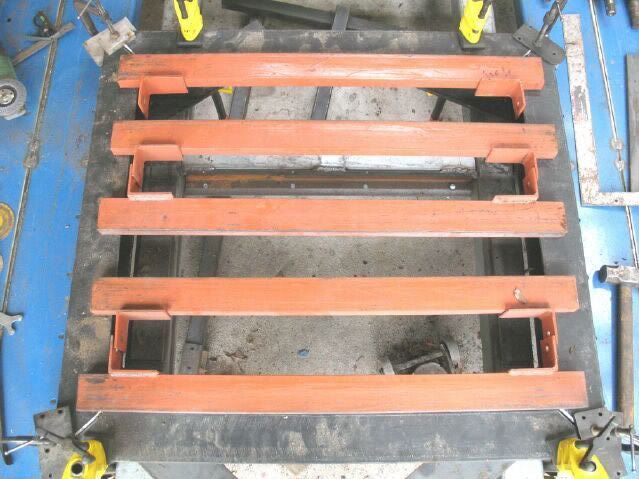
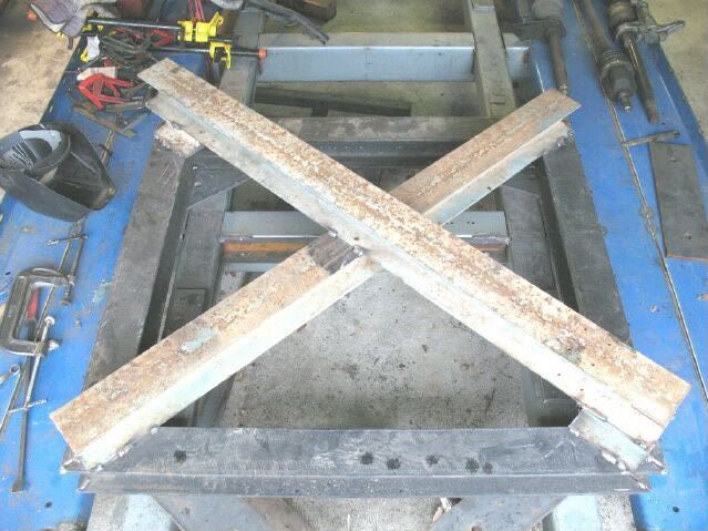
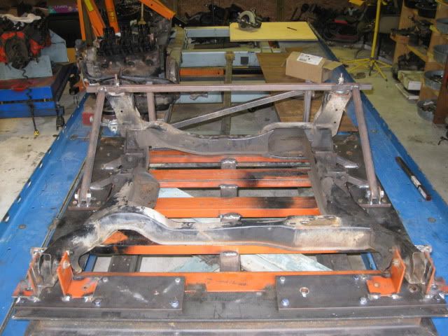
The cradle fixture will be used to mock up the cradle and all engine/tranny mounts. So it will have about 700+ lbs of drivetrain on it as well as the cradle. I want to make sure everything stays level and square even under that weight, so added some 4" I-beam X bracng to the underside of the cradle fixture. I still need to add the two shorter I-beams so it will be level across the bottom... this thing is going to be heavy!
IP: Logged
05:19 PM
Will Member
Posts: 14289 From: Where you least expect me Registered: Jun 2000


.JPG)
.JPG)
.JPG)
.JPG)