|
| Trinten's SBC/F23 build - The work has begun! (Page 33/76) |

|
katatak
|
FEB 17, 10:49 PM
|
|
Looking great as always Guru! I'd be highly interested in a set of your deck lid hinges. I can send you the hinges off my car if that helps. I now you are a busy guy - I'm in no rush but wanted to get on the list for future.
Thanks for sharing all your hard work.
Pat
Honored to own a page in Trinten's (Guru) Thread!  [This message has been edited by katatak (edited 02-17-2014).]
|
|
|
|
fieroguru
|
FEB 18, 08:07 PM
|
|
| quote | Originally posted by katatak:
I'd be highly interested in a set of your deck lid hinges.
|
|
Once I get Trinten's car done, I will make 2-3 sets of the hinges to sell and list them in the mall.
|
|
|
|
fieroguru
|
FEB 18, 08:26 PM
|
|
|
|
|
Doober
|
FEB 18, 10:49 PM
|
|
|
I missed the details of the engine, went back & looked... AFR heads are the tits, wish I had the $ for a couple sets (one for the 383 in my truck, one for the 350 in my Malibu). What intake is that?
|
|
|
|
Trinten
|
FEB 18, 10:53 PM
|
|
Thanks!
The intake is a (modified) Holley Stealth Ram setup.
I bought the setup from another member here on the board. It was originally modified to fit under a stock Corvette hood (it had decorative fins on top that he had lathed down, and trimmed down some other things). FieroGuru has modified it even further to make sure things would fit.
|
|
|
|
fieroguru
|
FEB 19, 07:57 PM
|
|
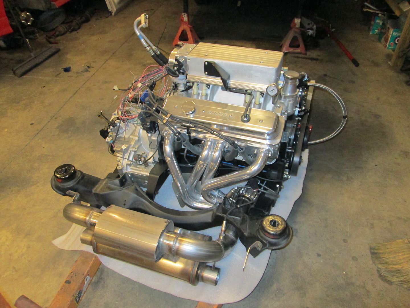
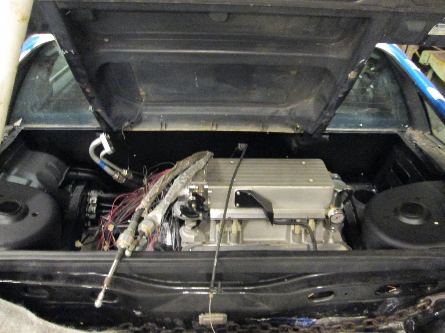
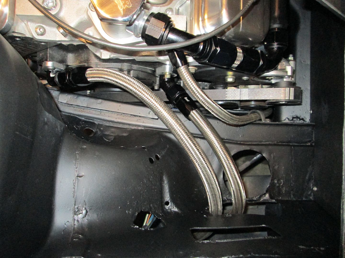
The top side of the engine has everything connected (except the HTOB - waiting on the replacement line).
Accessory side:
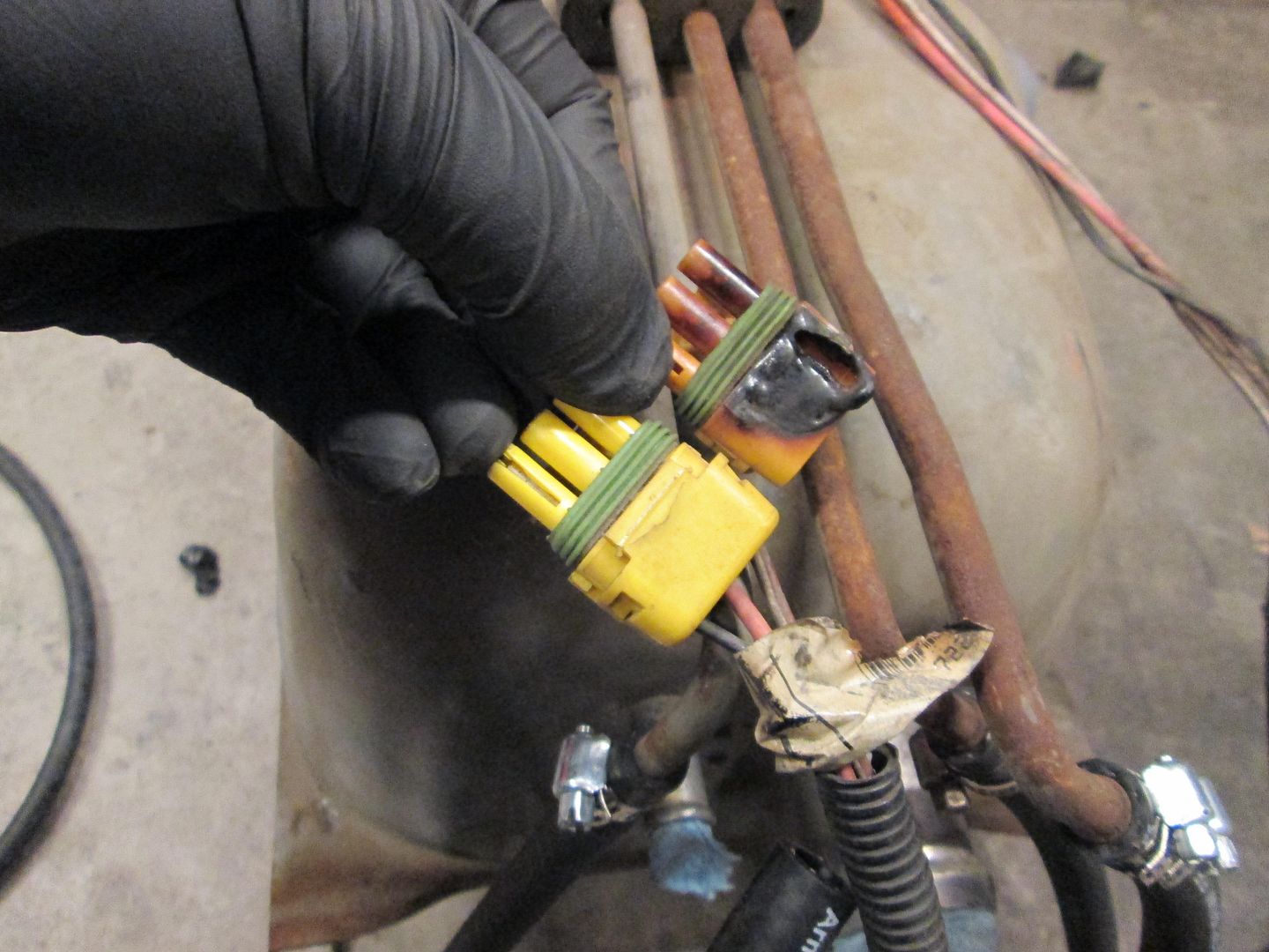
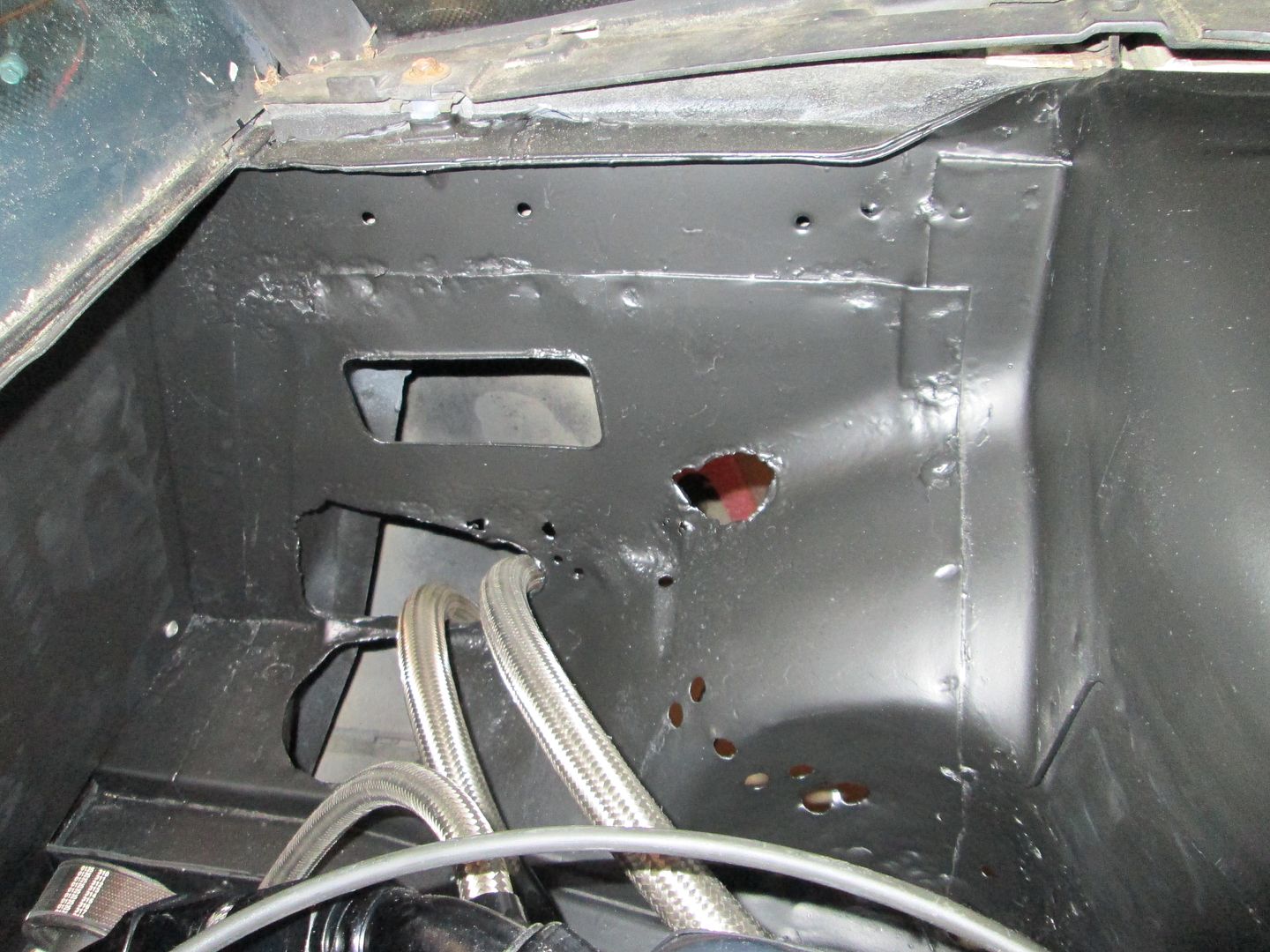
No 500 connector or any wiring for that matter in this corner:
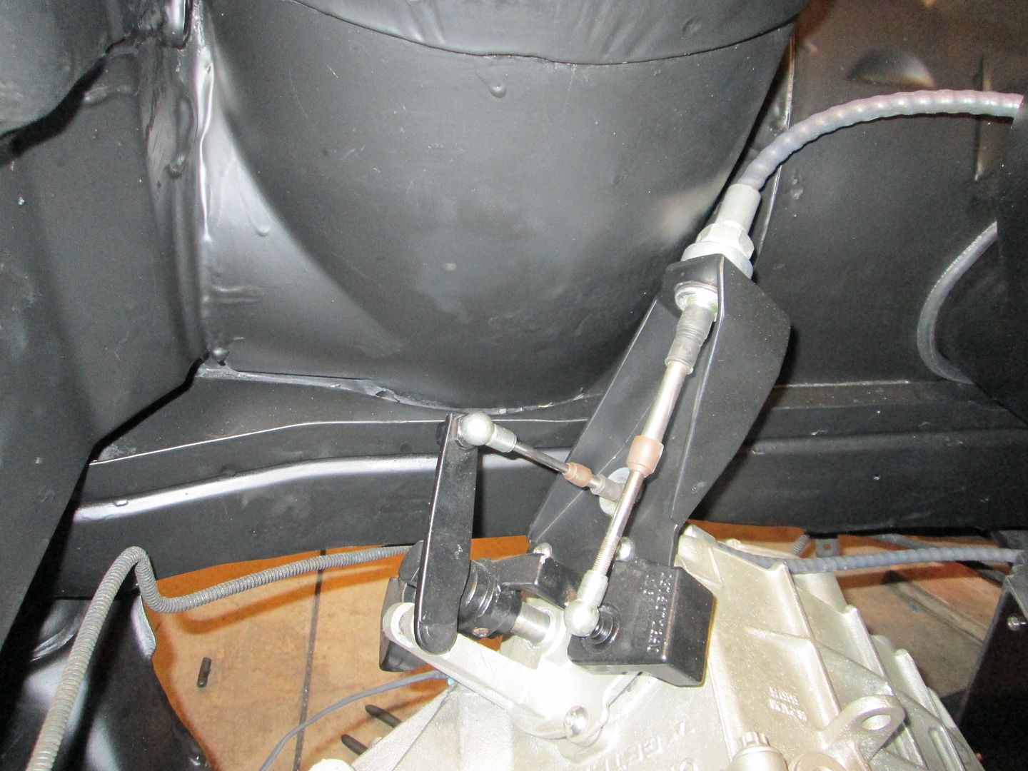
Reworked F23 shifter brackets:
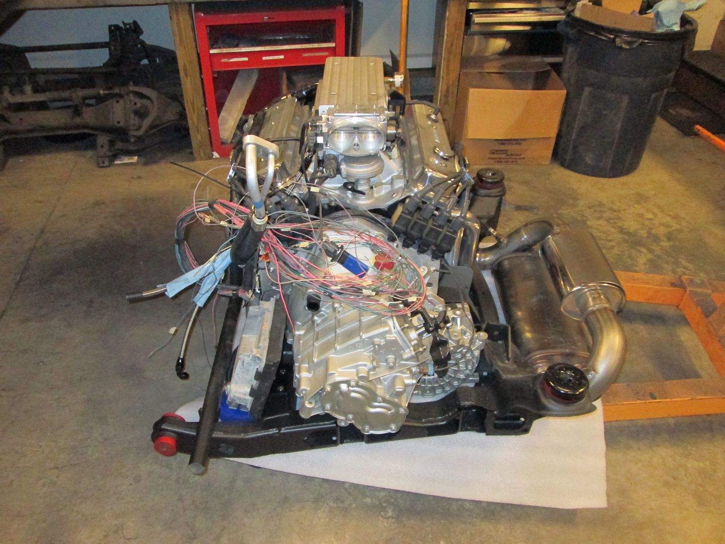
4" cold air intake passing into the wheel well. I lined the edge of the panel with some hose that I cut a slit into. No wiring over here either:
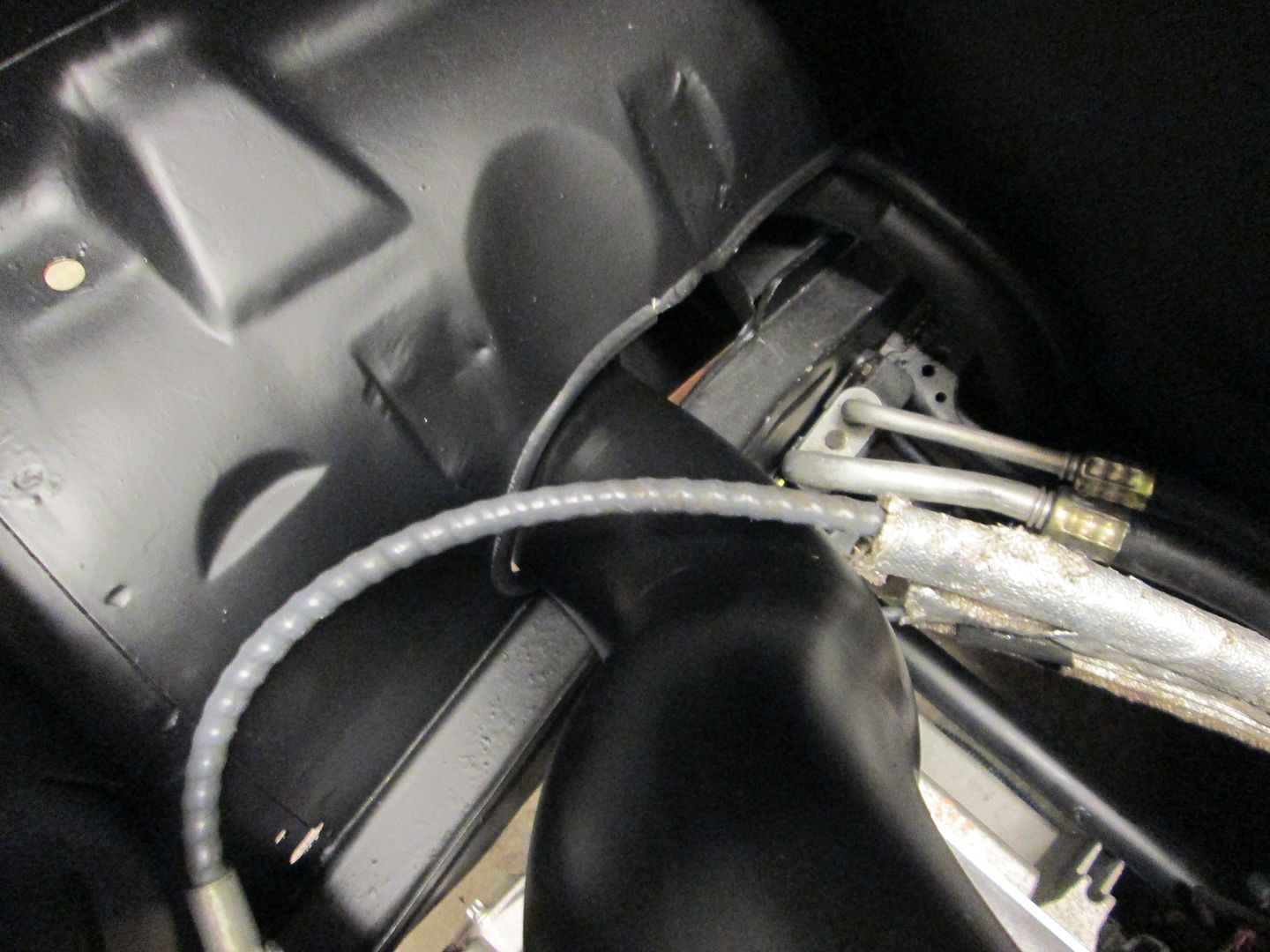
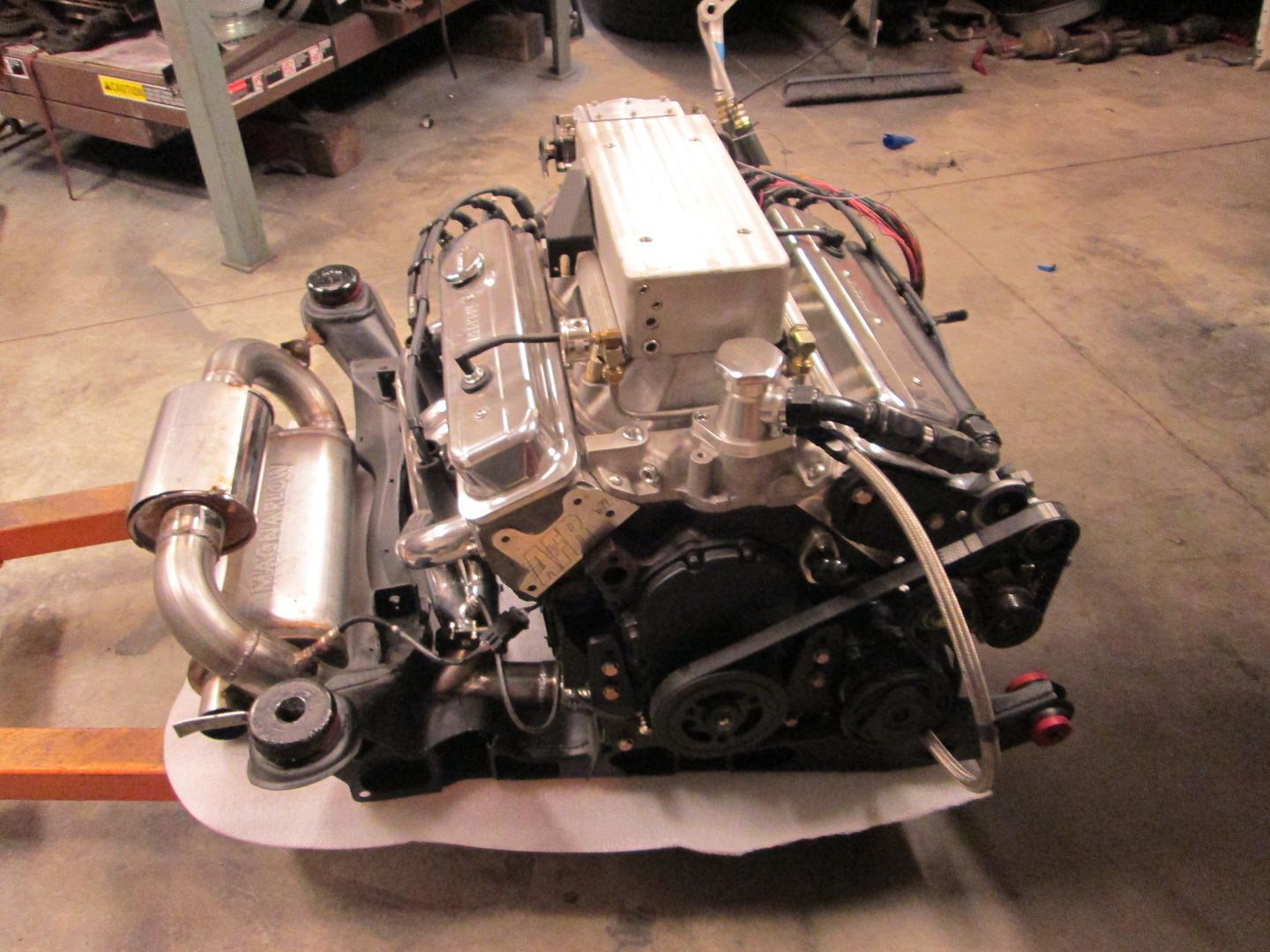
Transmission side of things:
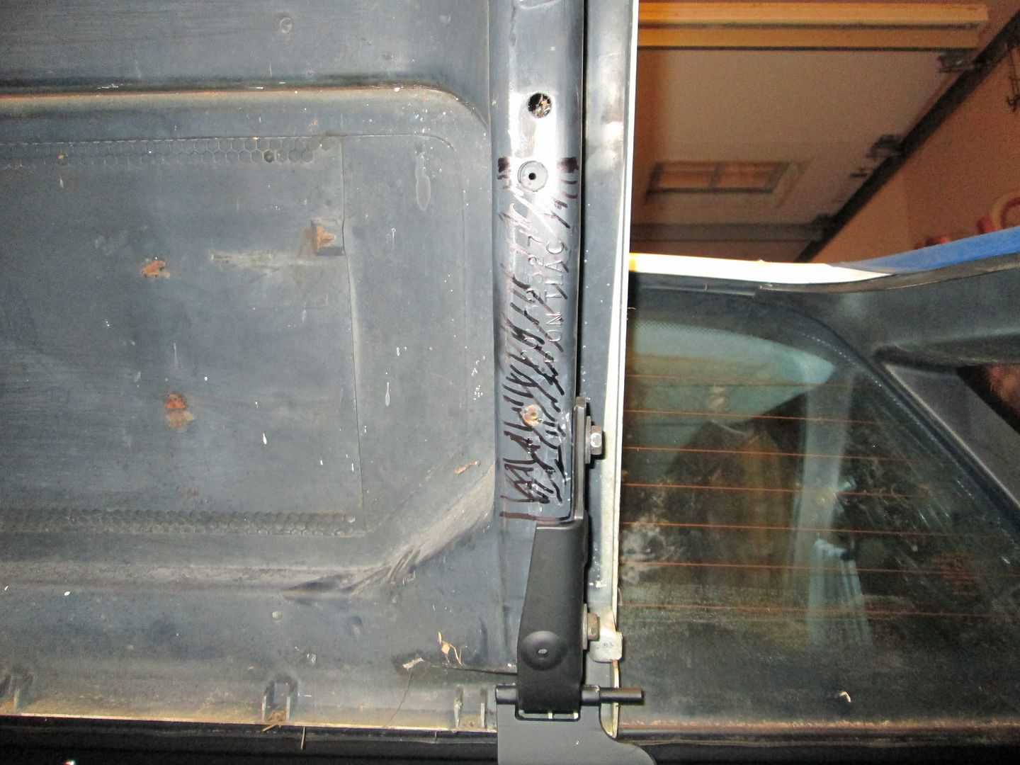
Smooth firewall, relocated wiring harnesses, modified decklid hinges:
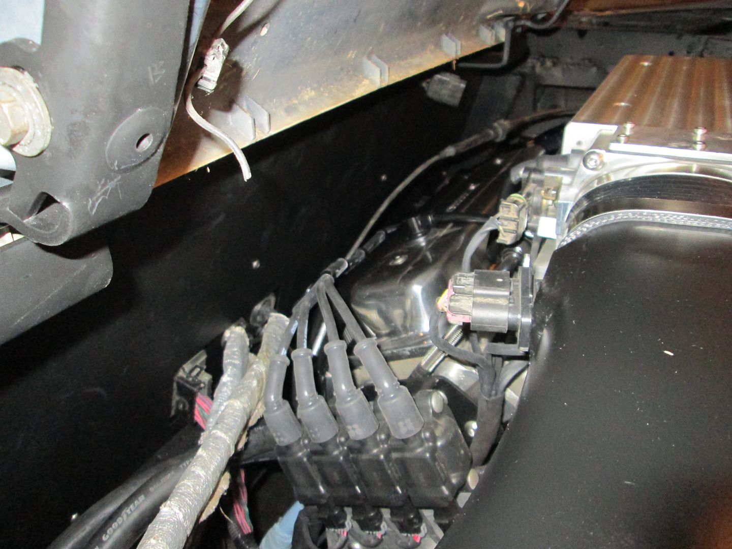
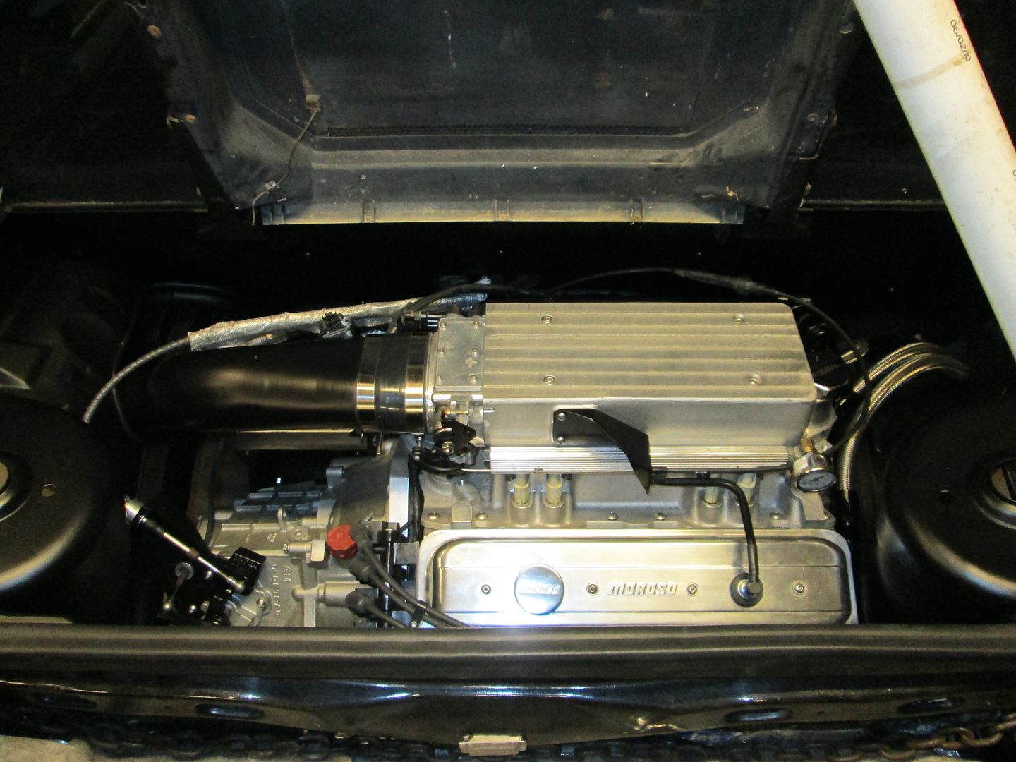
I wasn't able to fit the intake completely under the decklid and will have to remove a slight amount of material (about 1/8" to 1/4" deep):
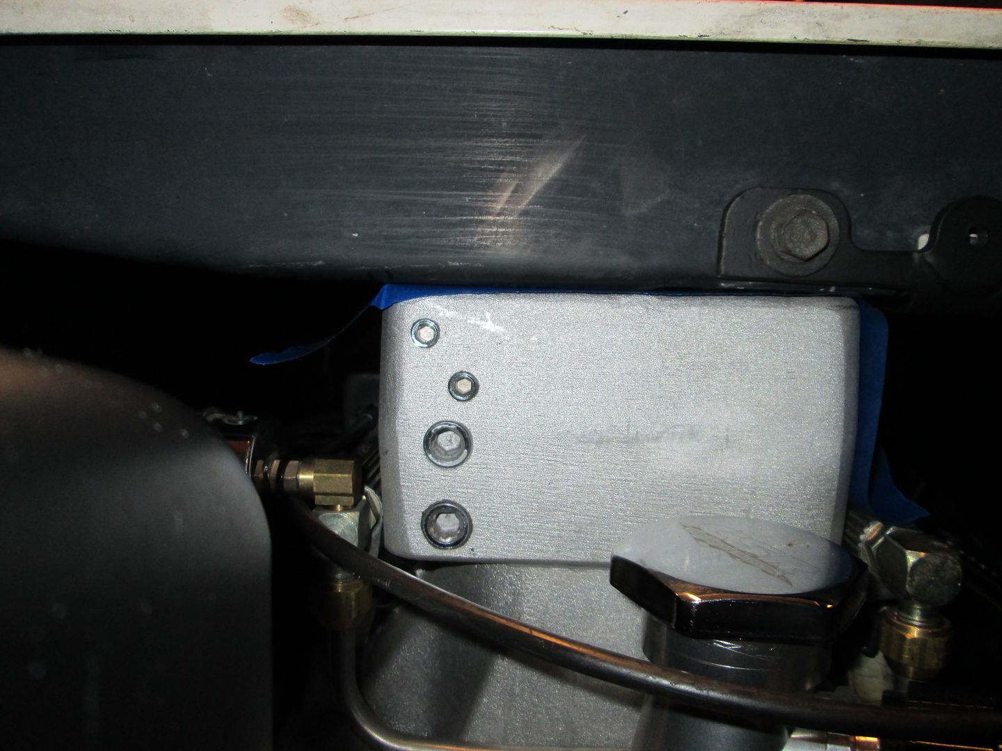
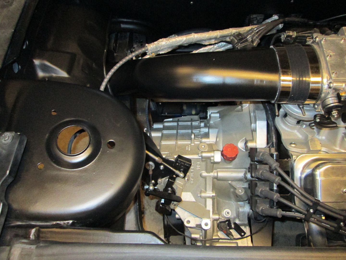
Pic of the engine from the side:
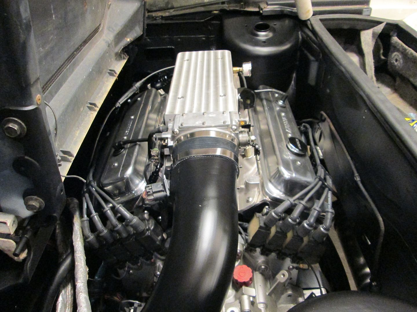
Here is a full engine bay pic of the engine. I still need to clean the bottom side of the decklid and install the struts, but this is very close to the final installation pic (engine side is fully wired too!).
Now I need to move to the interior and start working on all the interior harness terminations... that will take a couple of days.
|
|
|
|
Trinten
|
FEB 19, 09:12 PM
|
|
yeah, sorry about my old decklid being so terribly dirty. When I moved last year, I didn't have a shed or anything any longer to keep it in, so I had to set it in the backyard up against the house... I thought the overhang of the roof and gutters would help protect it - not as much as I hoped. It was pretty darn gross, but I didn't know it till CowsPatoot was there and we were loading parts up into his truck. Sorry again. 
|
|
|
|
ericjon262
|
FEB 21, 08:35 PM
|
|
|
|
|
fieroguru
|
FEB 23, 05:52 PM
|
|
I am just about finished with the inside wiring. Just need to add a connector for the clutch switch and wideband input, wire up the wideband, and solder the terminal on the end of all the grounds. The 500, 203 and OBD2 connector terminations are all complete.
The terminal strip is the engine side of the 500 connector (and the fuel pump and water pump). The relays (top to bottom) are: Water Pump, Fuel Pump, and AC. Bottom right is the added fuse for the hot wire of the fuel pump. Circuit breaker is bottom center. The black vertical "wire" running parallel with the terminal strip is a 1K resistor between a fused 12V switched source and the tach wire. It is needed to boost the tach signal so the fiero tach can read it.
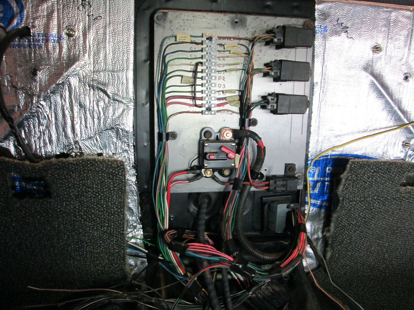
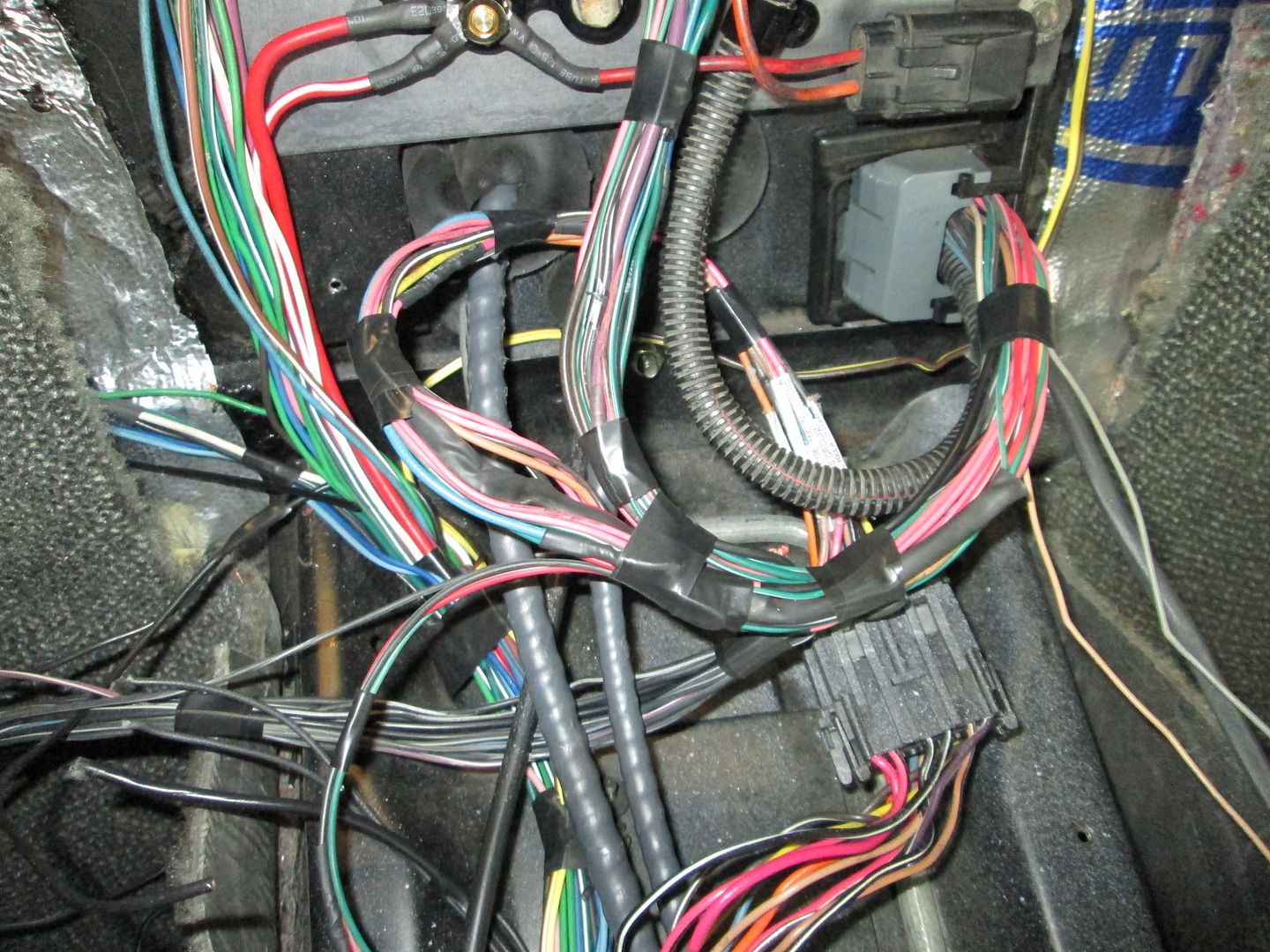
The harness comes in on the lower right of the console area, the 3 wires that immediately exit the loom are the clutch switch, wideband input to ecm and the wideband sensor harness. The harness loops around (I like to keep the harness long for any future mods) and splits with the OBD2 connector wires going to the front, all the 500, AC, Fuel Pump and Water pump wires going up to the terminal strip/relays, all the ground exit the harness to the left, and the harness continues to loop around to the 203 connector. Within the looping harness (thick black heat shrink tube at bottom of loop) bottom is the speedo circuit between the ECM and 203 connector so the Fiero speedo will work.
I will be traveling for work this week, so won't get back to working on this swap till next Saturday. Once I install the tank and connect the battery cables, I can try connecting to the ecm, do the first round of parameter changes in the tune and see if it will make some noise...[This message has been edited by fieroguru (edited 02-23-2014).]
|
|
|
|
Trinten
|
FEB 23, 09:05 PM
|
|
Your whole post just got cut and pasted into a file, and the images saved. 
This way in the future, if anyone asks me what was done or where a relay or fuse is at, I can go "Here, read this!" lol
That looks super clean man. I love the fuse/breaker thing, that's just a nice touch.
Thanks again!
|
|
|
|