|
| LS4 / F40 swap - fieroguru (Page 195/216) |

|
Trinten
|
FEB 09, 06:09 PM
|
|
Thank you for the pics and info. I admit I am feeling a little dense here. I can clearly see the u-bracket on the gauge, with the 'arms' moving to the face plate you made. But I don't understand what's affixing the bracket to the faceplate?
At first I thought maybe the bolt system would expand to act like a tension rod to hold the bracket between the back of the housing and the face, but then it's putting all that pressure outward on the face, which is being held on by the factory screws in the factory plastic threaded holes. I would imagine you wouldn't want to do that, out of concern of the plastic cracking. So I'm stumped.
|
|
|
|
fieroguru
|
FEB 09, 08:37 PM
|
|
Vince,
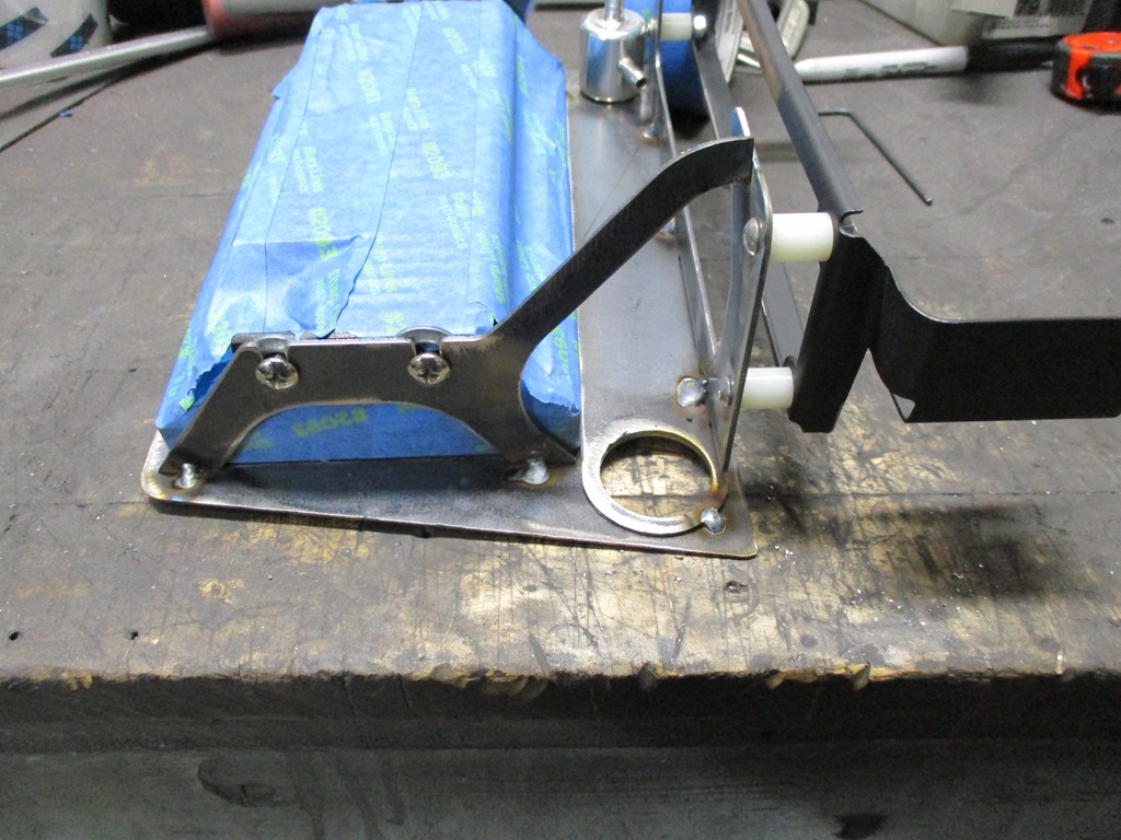
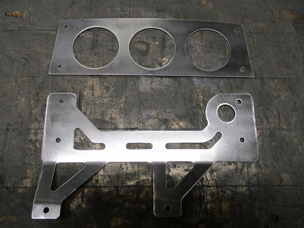
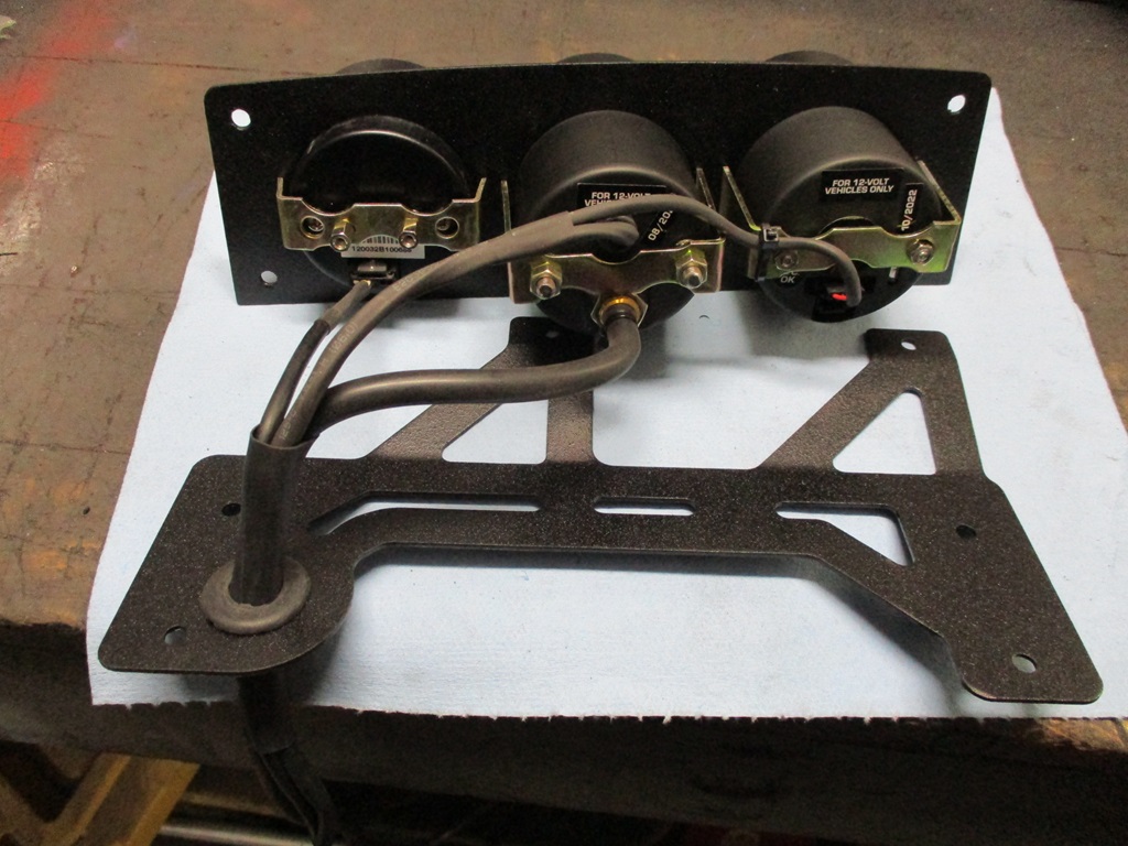
All 3 gauges will be clamped to the face plate with the U-brackets.
The face plate is attached to the housing with the 4 screws in the corners of the face plate.
The housing will be mounted to another bracket using the 4 bottom screw holes.
I am planning to have the gauges installed above the instrument cluster this weekend, so I can post some better pictures.
|
|
|
|
fieroguru
|
FEB 10, 09:09 PM
|
|
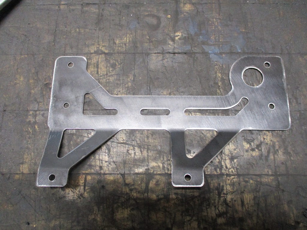
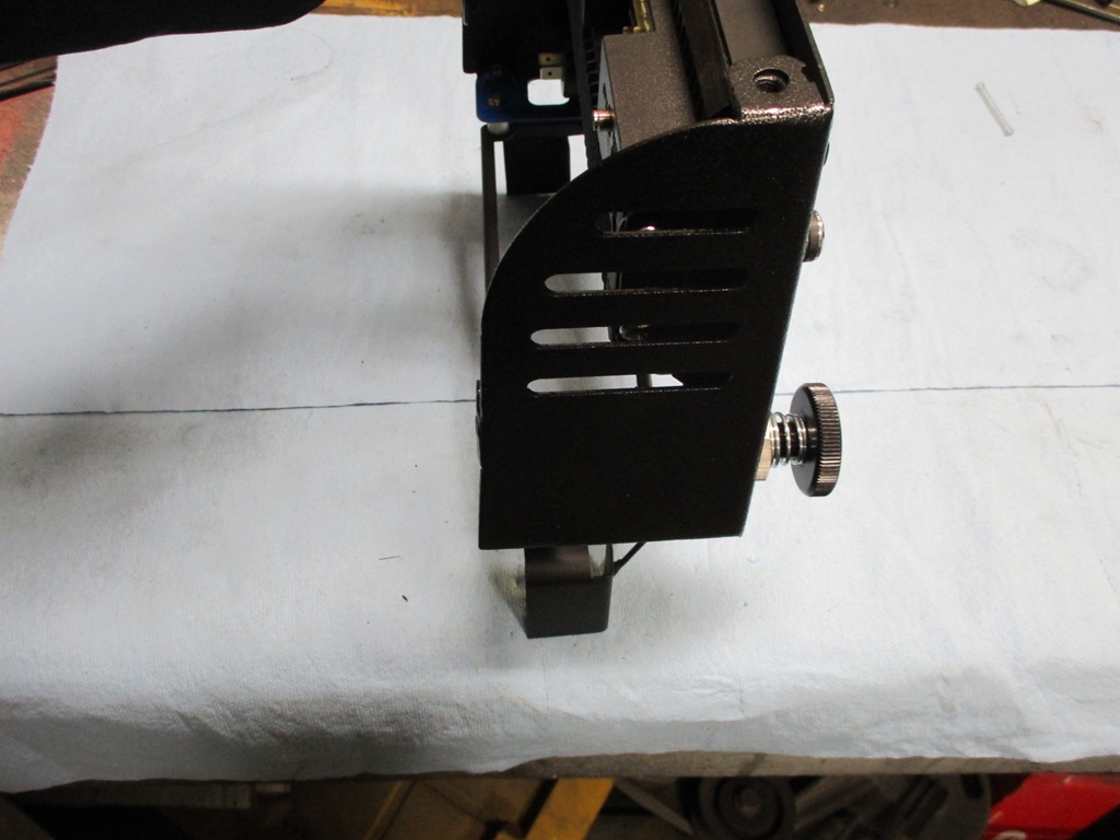
The work on the aux gauge bracket is almost done.
Welded up the steering wheel center. Still needs some more smoothing.
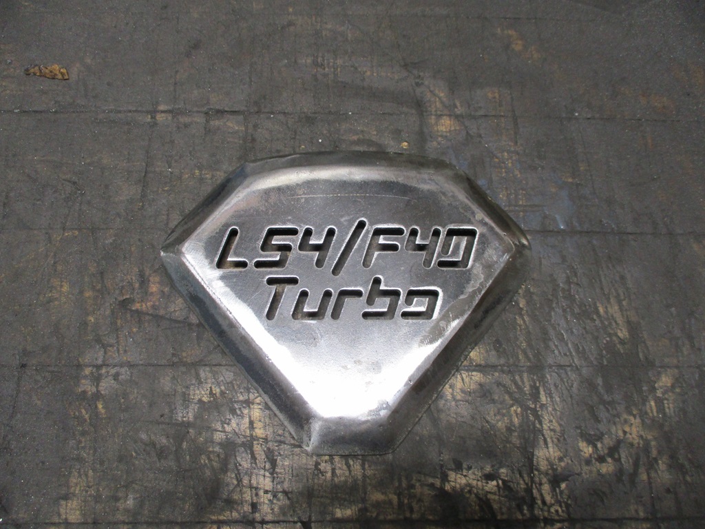
This is the soon to be insert for the steering wheel center:
|
|
|
|
fieroguru
|
FEB 11, 04:15 PM
|
|
|
|
|
fieroguru
|
FEB 15, 08:49 PM
|
|
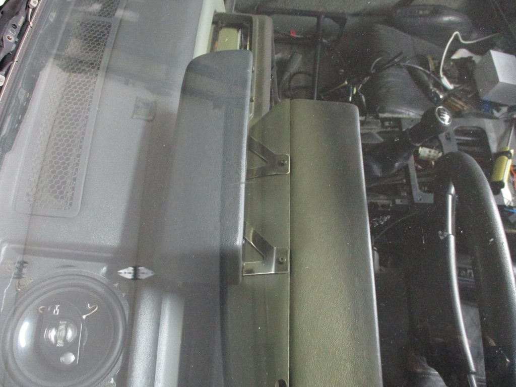
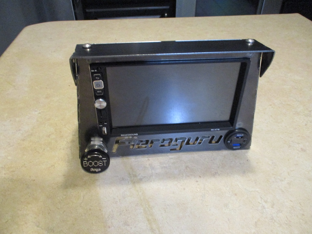
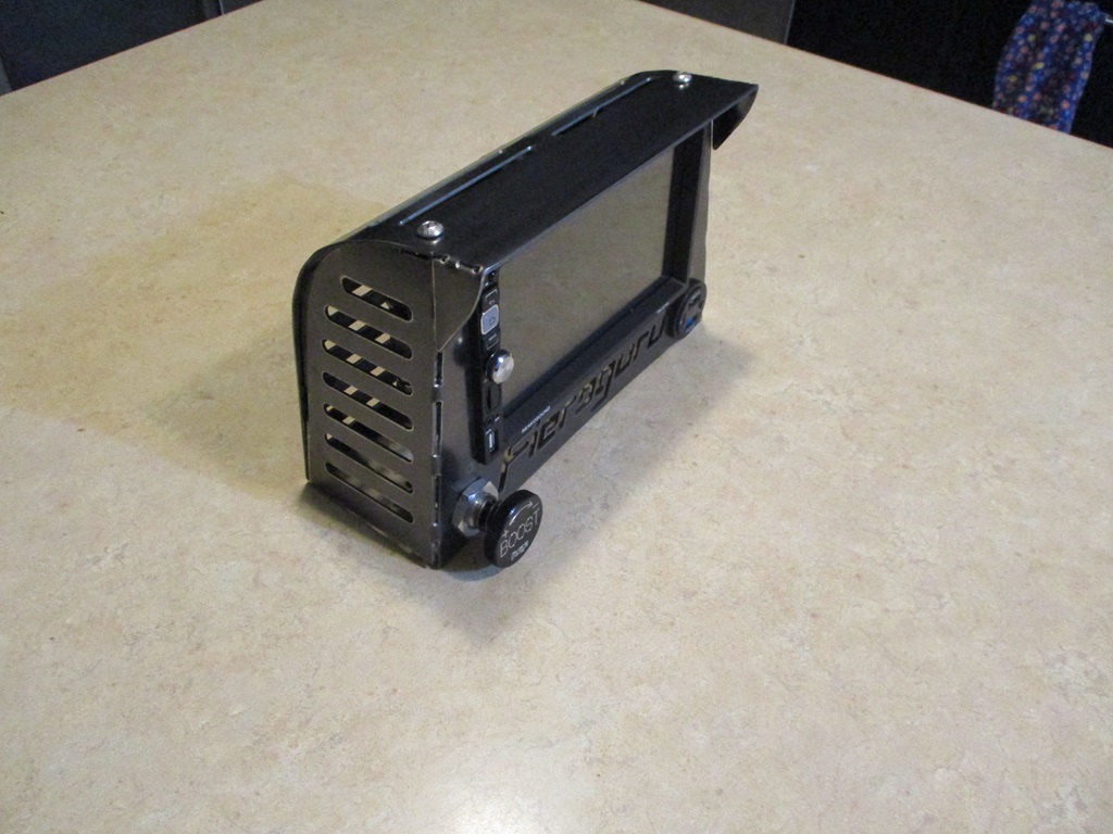
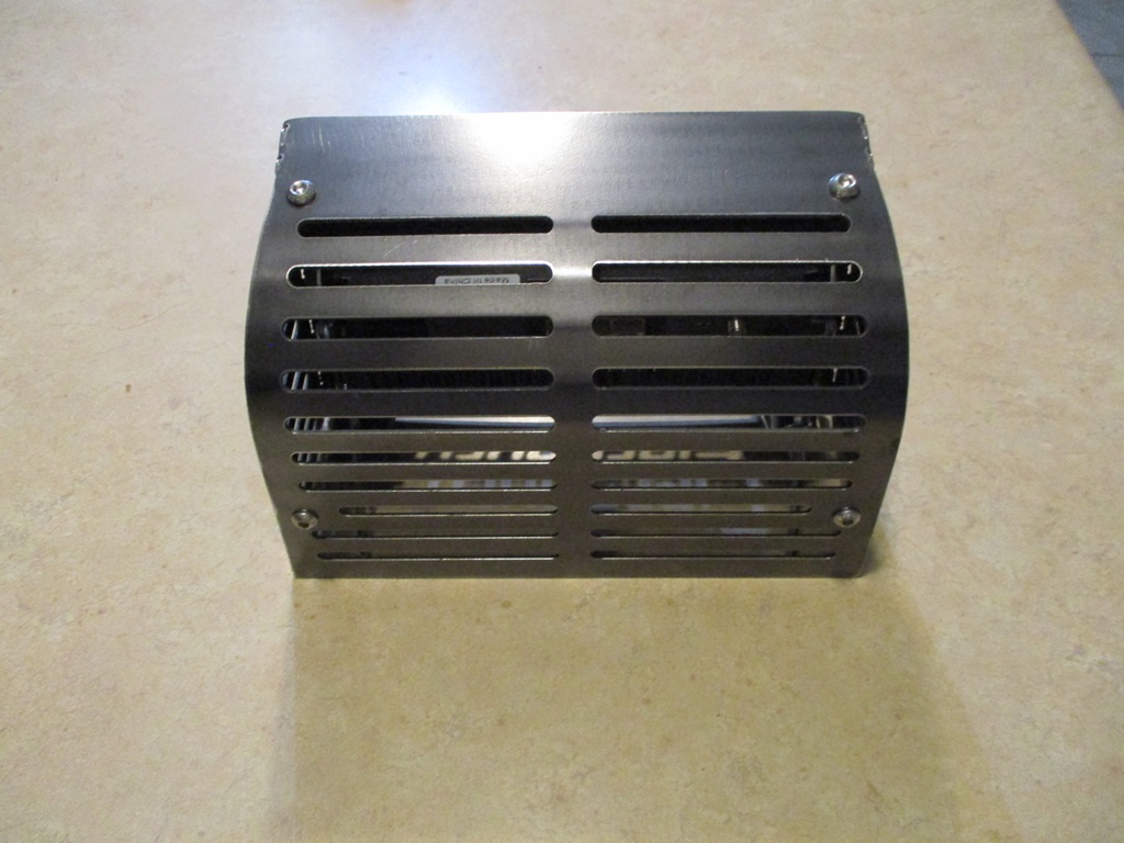
Playing around with options to enclose the radio...
The slots are for ventilation, lightness, and to access the 4 bolts holding the radio in place.
The back panel/front sun visor bolts on and I need to dial in the shape of it a little more.
Not really loving all the slots, but they are a start until I think of something more creative.
|
|
|
|
fieroguru
|
FEB 18, 05:03 PM
|
|
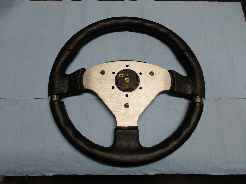
The steering wheel is getting closer. The center pod is finished. It is spring loaded and activates the horn puck that came with the wheel. Now I need to fabricate the adapter to allow it to mount to the Fiero column.
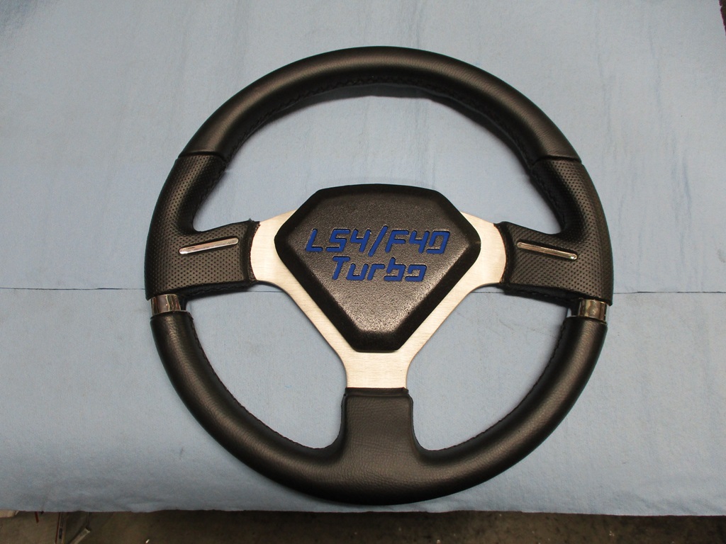
The new center piece reuses the same 3 bolts as the original center.
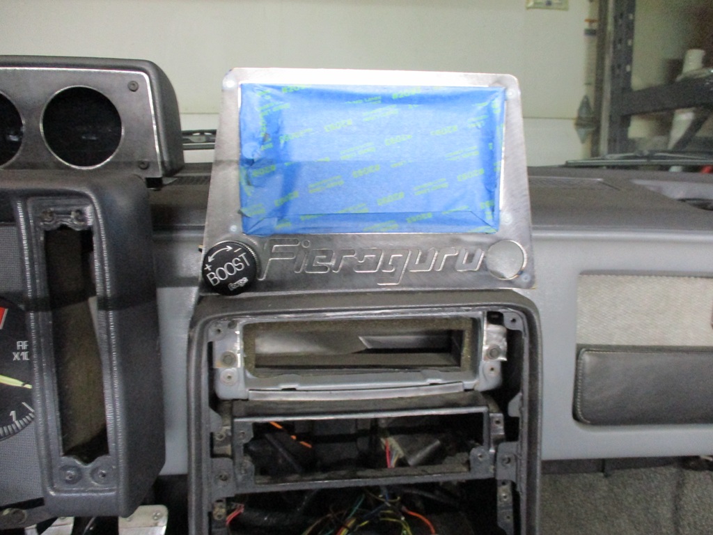
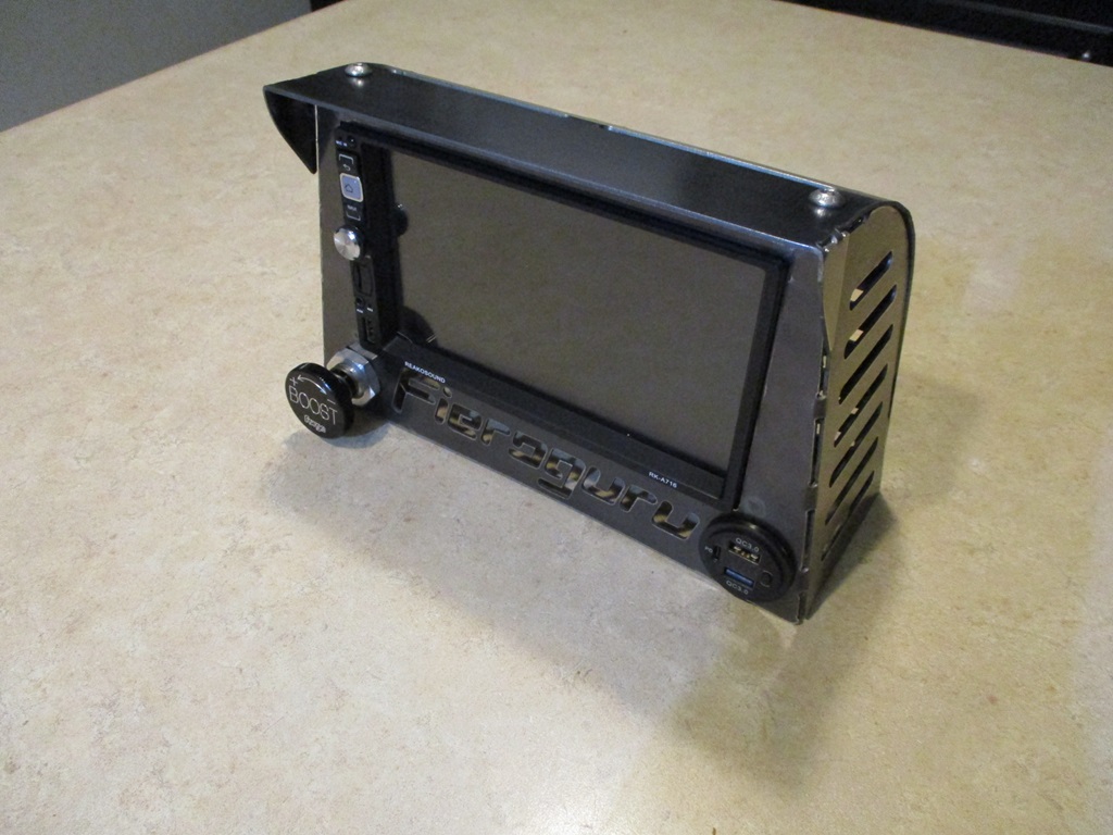
The radio/NAV face, sides and base are complete. Still need to finish the top/back panel. Thinking it will be aluminum.
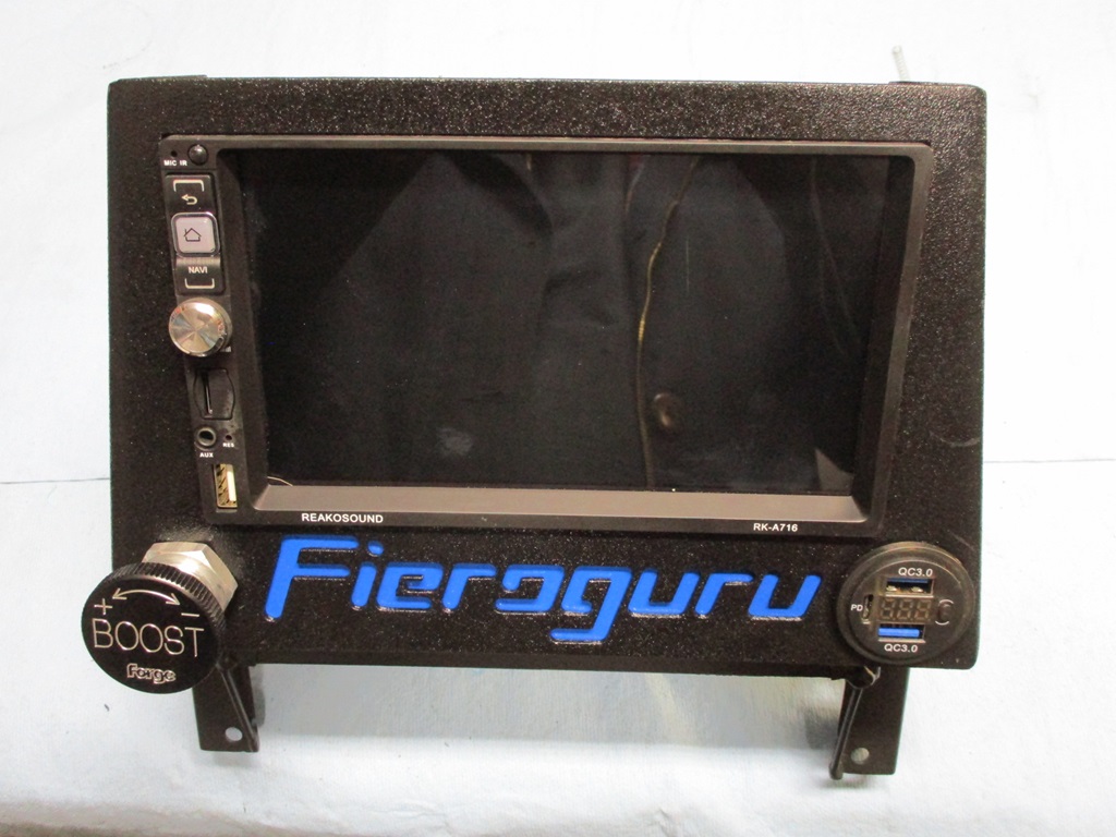
I ended up removing the lower slots on the side and just kept the top 4 (2 are to access the bolts holding the radio in place).
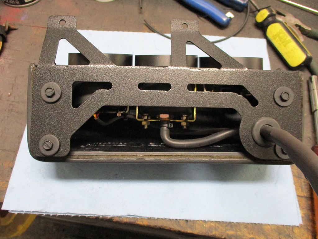
Here is the business side:
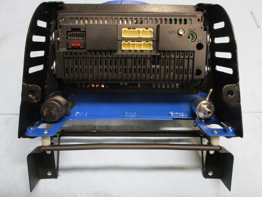
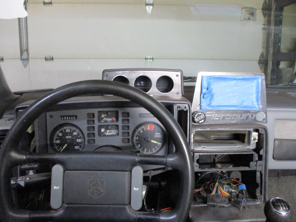
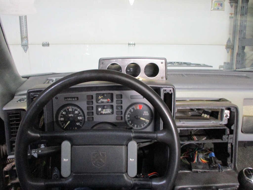
Also started looming up the 3 gauges - A/F ratio, Boost, and Fuel Pressure:
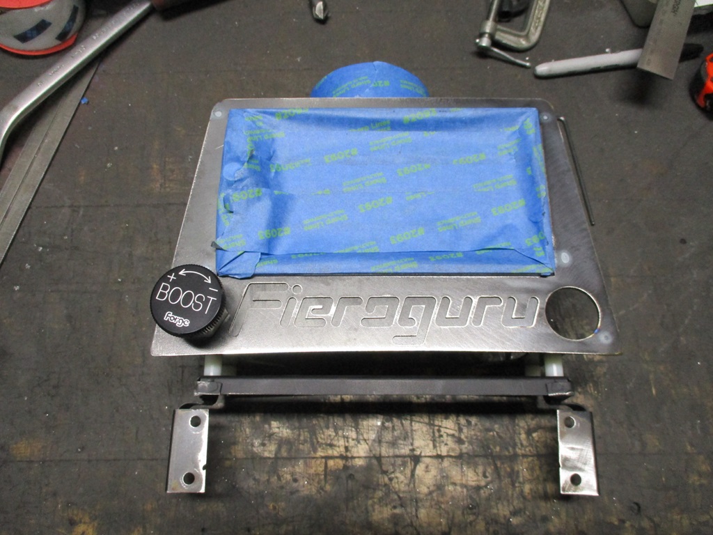
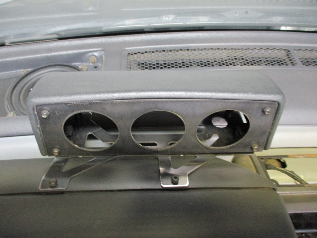
Gauge pod ready to be installed:
Gauges and Radio/NAV unit installed:
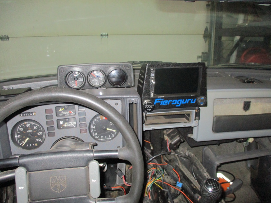
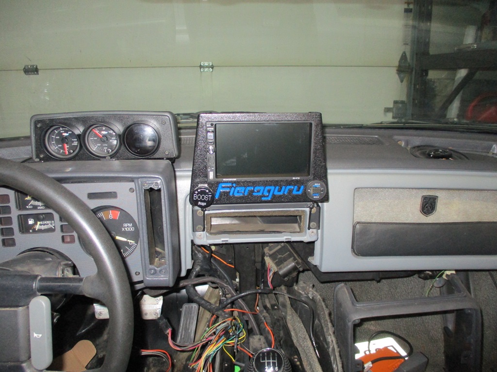
Now I can pull the dash and install the front speakers, the amp and wire up the radio...
|
|
|
|
kennn
|
FEB 21, 07:56 PM
|
|
|
You are indeed capable. All I want to do is wire my car for a TPI coil on plug like you did for Trinten and am entirely intimidated. On my behalf though I haven't seriously tried to actually figure it out. It appears daunting. Perhaps at one time it was for you also. Excellent work. ------------------
'88 Formula V6
'88 GT TPI V8
|
|
|
|
fieroguru
|
FEB 26, 07:09 AM
|
|
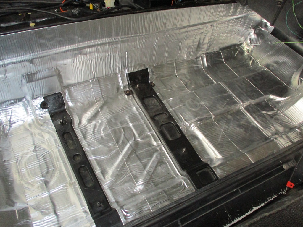
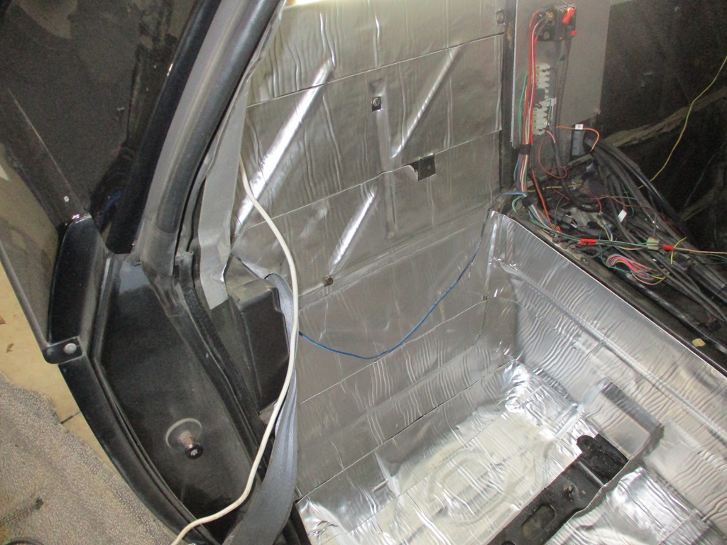
Currently have all the interior back out adding sound deadening. Passenger side is done:
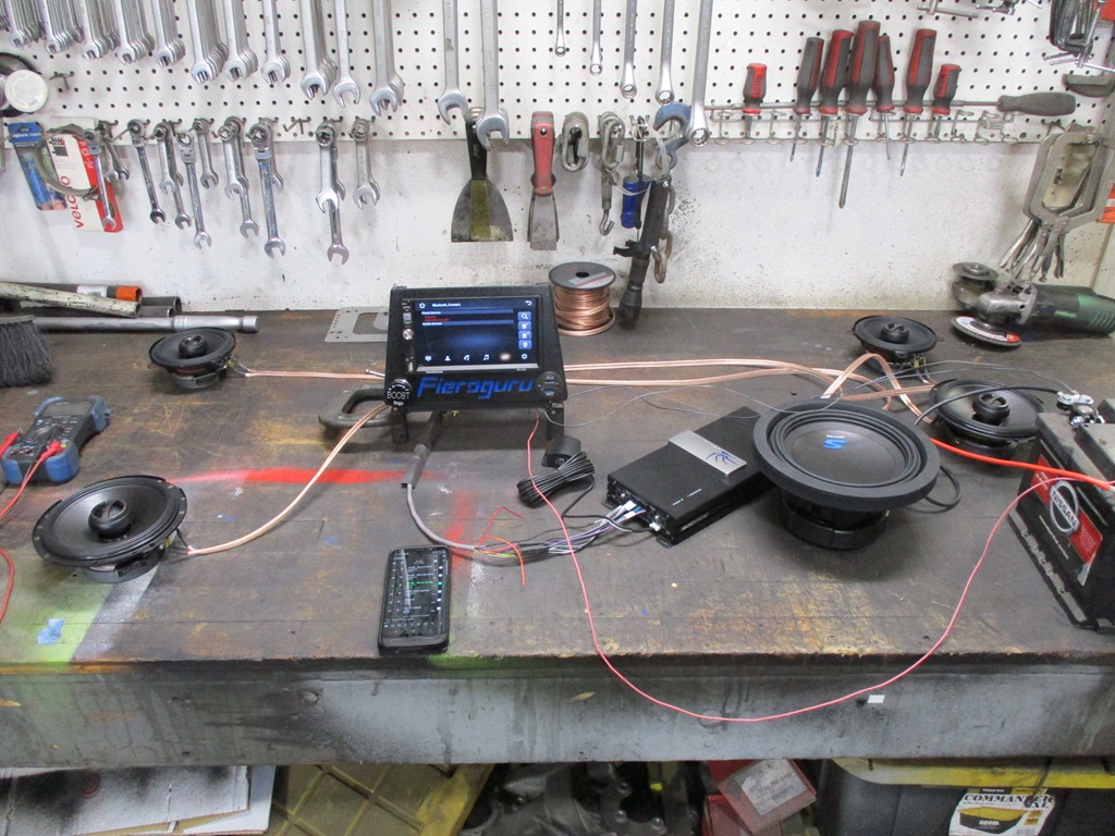
Also wired up the stereo amp and all the alpine speakers up on the bench to test them out.
Also started measuring and drawing the sub box. Ideal size for this 8" sub is 0.30 cubic ft sealed box. I plan to make it out of 16ga steel on the plasma in 2 parts, then weld it up. Easily have room for it under the dash. It is amazing how much more interior volume you get with 16ga vs.1/2" MDF.
|
|
|
|
fieroguru
|
FEB 26, 09:47 PM
|
|
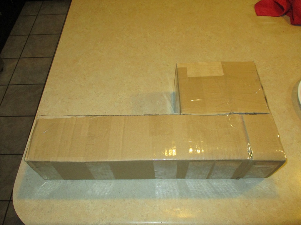
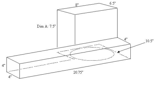
Played with some cardboard to mockup the box. This box is very similar to Alex4mula's, except it is 4.5" tall, the front tube is 4.5" deep, and the overall length/width is 20.75 x 10.5". I plan to make this out of 16ga steel vs. 1/2" MDF. Partly because the CNC plasma makes cutting these types of things easy and partially because it allows more air space in a smaller package.
With the relatively small span I don't expect the box will flex much.
As for the weight, a 4x8 sheet of 1/2" MDF is 66 lbs and a 4x8 sheet of 16ga steel is 81.7 lbs. so it would be easy to say the use of 16ga vs. 1/2" MDF will have the box weigh about 24% more. However, with the dimensions of Alex4mulas box remaining the same, the 1/2" MDF has 0.248 ft^3 and using 16ga is 0.376 ft ^3 or about 53% more interior volume. So, when you build a box to a specific volume, the steel one can be smaller, use less material, and overall be lighter.
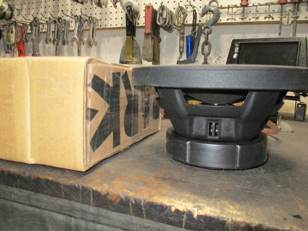
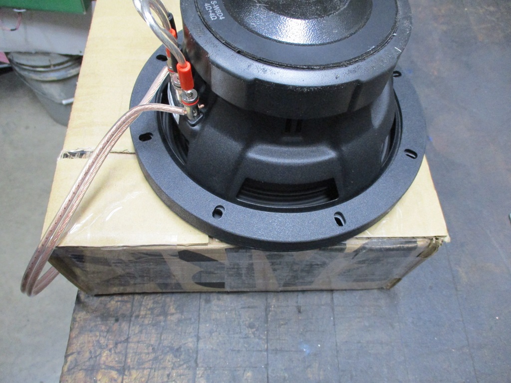
The 4.5" thickness easily clears the speaker magnet and subwoofer depth:
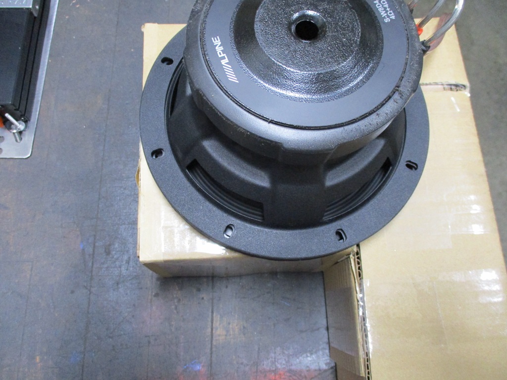
The 8" width portion has the sub flange hanging off the sides slightly, and from the mockup this could be wider as there is room on both sides - especially at the elevation of the sub flange.
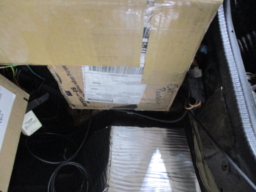
This is looking up from the floor to the box and the side where the sub would be mounted and there is a gap on both sides.
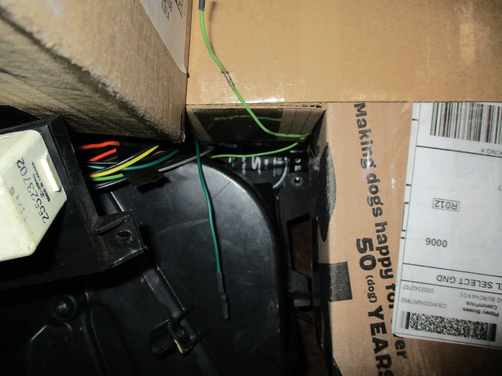
Here is the current clearance to the heater core. By removing the bracket, the box could be a little wider in the back:
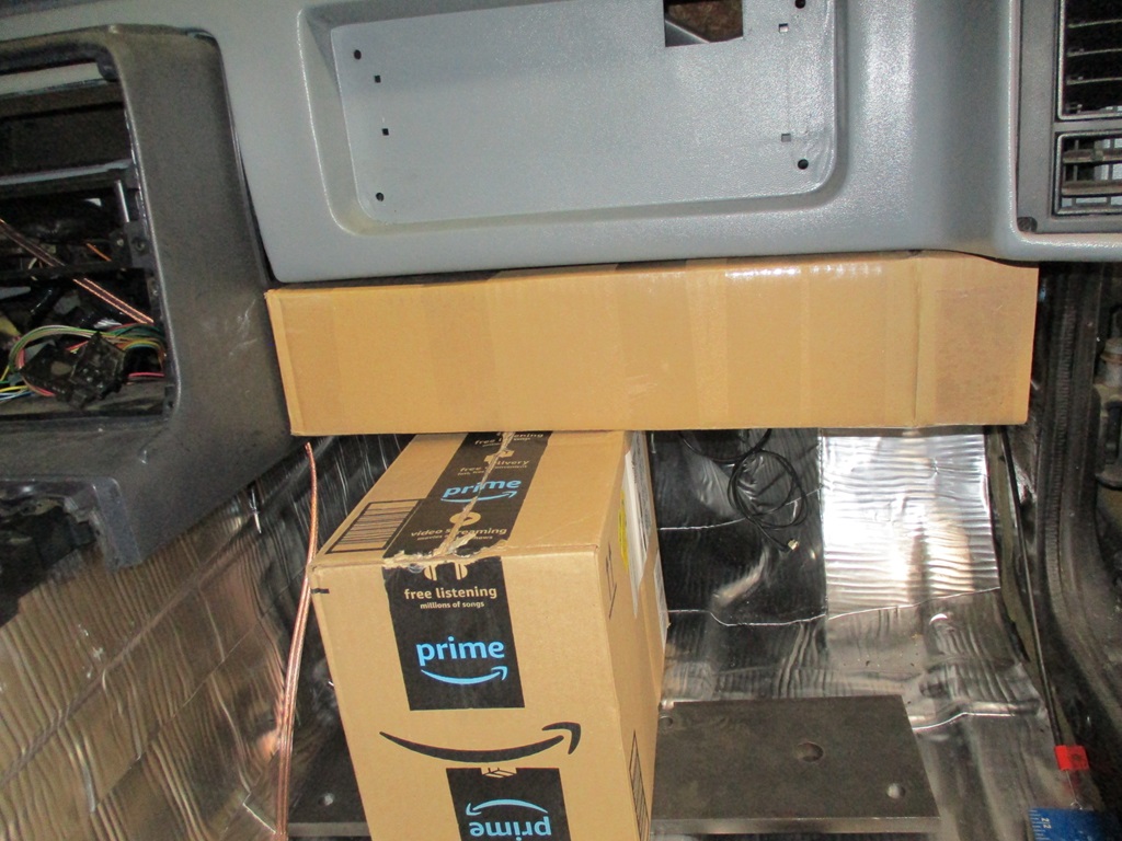
Here is a pic of the box installed from the front:
The recommended sealed volume for my sub is 0.30 ft^3 and this mock up box is 0.345 ft^3 so I need to make it a little smaller.
Current plan is to reduce the overall height by 1/4", reduce the front tube depth by 1/4", adding a 1 1/2" x 1 1/2" 45 degree taper at the lower corner of the front tube, and probably something along the outside edge as well.
The flat pattern is too large to cut as a single piece on the cnc plasma, but I can easily cut it in 2 pieces.[This message has been edited by fieroguru (edited 02-26-2024).]
|
|
|
|
pmbrunelle
|
FEB 28, 10:33 PM
|
|
I have some concerns about the panels of the box having resonances (high Q resonance due to the steel material) in the low audio-frequency / subwoofer range being excited and resulting in the panels buzzing, but I guess you'll find that out; maybe internal panels can be used to tie opposing faces together, or dynamat or similar.
Are you able to perform a modal analysis on the box?
If you're interested, I could run a modal analysis on SolidWorks, using your dimensioned drawing to define the part.
|
|
|
|