
 
     |
| Ecotec, Fastback, T-Top Build. (Page 17/22) |

|
cam-a-lot
|
JUL 17, 09:21 AM
|
|
That looks awesome bud! Nice work It is pretty neat when an actual metal fab professional gets on these forums and is able to make the parts that we can all imagine, but don't have the skills or tools to make.
I love the ecotec motor. I have driven a few of them, including the boosted ones, and in hindsight I think that is an even better swap motor for Fieros than the 3800. Light, powerful, loves to rev, and tons of aftermarket support.
Looking forward to going for a spin in this baby
|
|
|
|
Lunatic
|
AUG 08, 12:52 PM
|
|
Since I need a dog bone to limit engine movement, I made a custom one. This will not be mounted in the stock Fiero location and it will reside down low.
I'll use this hole for now. I will add a bracket later to create a double shear system.

On this end, I'll need to make a bracket.

Here's my design.

Off comes the engine and transaxle again so I can finish off the cradle.
Gussets added here.

A notch for the AC compressor was required. No biggie.

Dog bone lower mounts.


Here's the cradle completely welded.

Shot of the AC compressor notch. I made it a little bigger purposely.

Then I decided to notch the frame slightly to allow clearance for the F23. Much better.


I will now take a break from welding and add primer and paint to the frame notch. Then it's off to sandblast the cradle and mounting brackets.
|
|
|
|
Will
|
AUG 08, 05:23 PM
|
|
Your dogbone will be almost totally ineffective.
It's too close to the axle centerline and where it attaches to the cradle it's perpendicular to the direction it needs to be going.
|
|
|
|
Lunatic
|
AUG 20, 01:31 PM
|
|
After sandblasting the cradle, I painted it to match the engine bay. Then I reinstalled the drivetrain.

Here's a few pictures of the clearance the Ecotec in a Fiero provides. Man, this is easy to work on.


I slightly shaved the bottom of three ribs on the F23 for additional trans to cradle clearance.
I did leave some material but it's not that easy to see.


As you can see, the drain plug is still accessible. This will make maintenance easy.

The frame notch worked out well. Clearance is great but very difficult to see in this photo.

Then I decided to remove the springs from the struts and check for full suspension movement.

With the axles installed dry, and with no boots on, I checked travel on both full droop and compression.


At full compression, the passenger side axle just touches the dog bone. I'll address this next week.

Then I painted the PCM black and reinstalled.


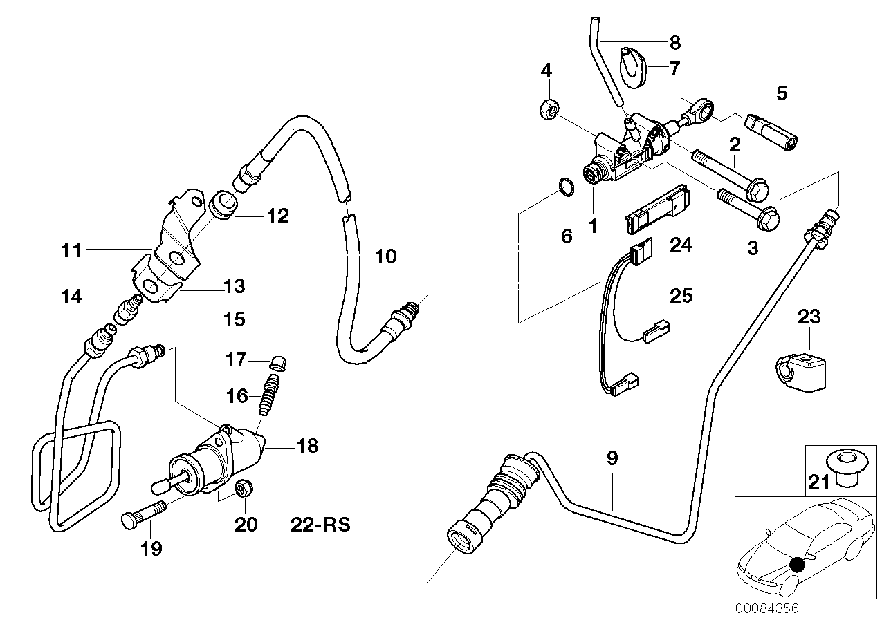
Knowing that BMW also uses Getrag transmission's in their cars, finding a suitable clutch hose was easy. If you look at the top left, you can see the part number. (21 52 6 774 267)

Here is the original Cavalier clutch slave and its associated parts. I only need the bleeder, the piece in the middle.

This plugs perfectly into the BMW clutch flex line.

Then install back into the F23. It's a perfect fit and there's no other fittings needed.

As you can see in this picture, the protective sleeve is in the perfect position. This will protect the clutch line from rubbing on the frame. It's like it was meant to be.

Here it is zip tied to the bottom of the frame rail.

I filled the Rodney Dickman clutch master with fresh DOT 3 brake fluid and left the bleeder screw open. After a few minutes, I topped the reservoir up again as the fluid made its way through the line. I closed the bleeder and had my assistant pump the clutch pedal. Within only a few minutes, the system was bled and leak free. It was so easy, a cave man could do it. It's nice having one of my three pedals working.
Note: In my application, these components (RD clutch master and F23 slave cylinder) play well together. Other swaps, with F23 conversions, may need a spacer between the pressure plate and slave cylinder to prevent the slave from over-extending.
|
|
|
|
Will
|
AUG 21, 11:51 AM
|
|
| quote | Originally posted by Lunatic:
Knowing that BMW also uses Getrag transmission's in their cars, finding a suitable clutch hose was easy. If you look at the top left, you can see the part number. (21 52 6 774 267)
Here is the original Cavalier clutch slave and its associated parts. I only need the bleeder, the piece in the middle.
|
|
Interesting find.
http://www.realoem.com/bmw/...MW_M3&diagId=21_0094
Do you have the part number for the F23 bleeder gizmo?
|
|
|
|
Lunatic
|
AUG 21, 04:06 PM
|
|
| quote | Originally posted by Will:
Do you have the part number for the F23 bleeder gizmo? |
|
Will,
The bleeder is not available for purchase separately. It must be purchased as an assembly and comes with the components as seen in this photo.
Should you need one, I have a used one that I can send you.
The Dorman part number is: CM640069
 [This message has been edited by Lunatic (edited 08-21-2016).]
|
|
|
|
Sage
|
AUG 21, 11:28 PM
|
|
Great build, progress and documentation! 
Don't understand why this is not in the construction zone already.
Keep posting the updates, another one of the "great" build threads!
HAGO! 
|
|
|
|
Lunatic
|
SEP 04, 08:22 AM
|
|
| quote | Originally posted by Sage:
Great build, progress and documentation!
Don't understand why this is not in the construction zone already.
Keep posting the updates, another one of the "great" build threads!
HAGO! |
|
Thanks for the compliments Sage. Here's a little update for those following.
I kept busy by cleaning the throttle body.


Now that it's clean, I reinstalled onto the engine. While close to the firewall, there is still clearance to run a 90° elbow in this area.

The stock four cylinder throttle cable fits into the Ecotec throttle bracket. Woot woot.

Surprisingly, the stock throttle cable slid into place. I suppose I could've cut the end down slightly but I decided to leave it. I verified WOT (wide open throttle) by having an assistant depress the throttle in the car. The throttle blade opened to the max. It's like it was meant to be.


Since my car came with a pin switch to operate the trunk light, I didn't like the look of it. So I removed it. The newer cars came with the trunk switch in the latch/striker area. I liked the look of that better and found the appropriate switch. What I needed was a good ground to the release solenoid. I removed the harness and added a dedicated ground wire.


Then I drilled a hole in the firewall to pass this new trunk wire assembly into the cabin.

I'll have to clean this up and secure it.

I moved on to wiring the new trunk circuit as well. It sure is nice to have an operational trunk release and trunk ajar light working. With having said that, I was still missing the trunk light though. I decided against putting the stock trunk light bulb back into operation. That little sucker gets hot! With having a tackle box full of odds and ends, I decided to build an LED light assembly. I re-purposed a few things and here's what I came up with.


While it's difficult to take a photo of an LED light, I turned out the basement light and this is the best shot that I could come up with. If it's bright enough to light up the ceiling, it'll be good enough to shine light into my trunk.

|
|
|
|
Lunatic
|
OCT 09, 01:00 PM
|
|
A few remaining wiring tasks for my swap involved wiring up the BCM (body control module) and modifying the A/C circuit. Let's discuss the BCM first. The only circuit on the BCM that I was interested in was the interior light control. In this case, it softly dims the interior lighting after closing the doors, like many new cars do. It also puts the interior lights on a timer. This is a nice feature. For example, when cleaning the car and leaving the doors open, the BCM turns off the interior lights after a preset amount of time. I chose to wire in this feature only. The BCM I'm using is part number: 22682857. This is just a plain BCM and it didn't come with the key-less entry feature.

Since there were many places that I'd have to tap into, I chose to remove the dash. This BCM requires several points of power and these came from a few different circuits. Some require full time power while others need key-on or accessory power. The back side of the fuse panel was chosen for all my power taps. In this manner, all BCM circuits are protected by fuses.
After the primary battery, accessory power and ground was wired to the BCM, it was then time to redirect the power and return for the courtesy and dome lighting to the BCM.
Note: S (ex, S210) stands for a splice location in the harness and C (C200) stands for connector.
I needed to cut the courtesy and reading light supply (orange wire) to make this work.
1) Follow the driver's side courtesy light (orange wire) to the S210 splice location in the harness and cut it leaving an inch or so before the connector. I chose to cut the wire on the “main harness” side.

2) Follow the orange wire coming from the dome/reading lights back to the C200 connector under the dash at the extreme left, upper forward corner. Cut this wire a few inches before it goes into the connector.

Join the orange wire “going to the dome lights”, at the S210, together with the orange wire “going to the courtesy lights”. Attach another wire and run this to the blue connector, pin A10 (Inadvertent Power Control) on the BCM.
This now leaves two orange wires that were previously cut. Extend the orange wire, coming from the C200, (that used to feed the dome/reading lights), to the orange wire that previously fed the courtesy lights (S210 splice location). Join these two wires together and add another length of wire. This goes to the BCM blue connector, pin A12. In reality, the Fiero courtesy light fuse is now feeding pin A12 at the BCM.
Another circuit that needs to be modified to make this all work.
At connector C209, there are two white wires. One goes to the passenger side and this is the one you want to cut. This white wire goes to the Fiero dimmer switch. Cut it around an inch from the connector. Extend this white wire and attach to the BCM brown connector, pin A1 (Courtesy Lamp Control). The other end is no longer used and should be capped.
Having now wired the the interior light's feed from the BCM, I must complete the circuit and add the return path.
Here is the S304 factory splice in the harness. It has four white wires acting as a node. (A place where two or more wires are attached.)

We need to separate these as follows.
Cut the single white wire, from the node, that goes to the right.
This wire leads to the right door jamb switch.
Solder a light blue wire to this white wire (that goes to the right door pin switch) and attach to BCM purple connector, pin A8.
Of the three remaining white wires, one goes to the left door jamb switch.
Follow/trace the correct white wire and cut it at the node.
Solder a light green/black wire to this white wire (that goes to the left door pin) and attach to BCM purple connector, pin A7.
You now have two white wires from the node. These are the courtesy and dome lamp returns.
Solder both of these together and add a length of white wire to this node.
Attach this to the BCM brown connector, pin A1. (Courtesy Light Control.)
At this point, the BCM now turns on and controls the courtesy and dome lights.
To deal with the A/C, I will need to modify the Fiero circuit slightly. Since I'm adapting a newer technology Delphi CVC-6 compressor to an older car, I need to make sure they play together nicely. This will be easily accomplished.
Here is the stock Fiero low pressure switch.

For testing reasons, I removed this connector from the pressure switch and jumped the two wires together. This is to make sure I have power in the HVAC control head and relay. Again, only for test purposes.

I'm doing this because the Ecotec PCM will now control the compressor cycling operations. I will also add in the three-wire pressure sensor to the high side line near the compressor. This must be done for safety reasons. The PCM uses this sensor reading to determine how to control idle speeds, radiator fan operation and A/C compressor clutch operation when the A/C system is turned on.
Note: the PCM will not enable the A/C clutch without having this sensor in place. From a safety stand point, this circuit also protects the A/C compressor. When you get into power enrichment, the PCM de-energizes the relay which turns off the compressor. Thus, saving it from over-speeding.
I then made a little bracket to hold the antenna parallel to the ground. Seeing as I shaved the antenna hole in the fender, this was my solution. I'm sure it's not the greatest position for an antenna to be in, but I use the auxiliary input more than I listen to the radio.

While I was in that general area, I also added new metal to support the passenger's side lower fender. One hole and a little primer/paint, it'll be good again.

Then it was time to get greasy. New CV joint grease was applied to all four joints followed by new clamps. Prior to installing the axles into the car, I installed new axle seals into the F23.
Napa part number: 13750.

I reclaimed this factory GM security unit from the Cavalier that I had here, GM part number: 10953186 .
It's a simple device that requires a fob to be swiped in order for the starter to engage. This will work well for my application and is all I need/want.


Lastly, I picked up a used 130 amp DC TIG welder. It's a portable Thermal Dynamics unit that only welds steel. I tried it and it works well but I will give it a good cleaning before it goes into service.
 [This message has been edited by Lunatic (edited 10-21-2017).]
|
|
|
|
Lunatic
|
NOV 01, 05:37 AM
|
|
I took advantage of the warmer weather and decided to apply undercoating to the bottom of the car. It looks way better and I like the full coverage.
Knowing that I also sprayed it above the coolant lines is piece of mind.
I then installed a new thermostat, water log housing and exhaust manifold.

As well as the exhaust manifold heat shield and oxygen sensor.

I cleaned up the belt tensioner and installed it. At this point, I'll just order a short belt to run the alternator. After I test it that is.
I'll wait until the spring to get the A/C lines made up and hook up the air conditioning at that point.

The 88 coolant tubes that I had weren't perfect by any means. The driver's side was okay but the passenger side was kinked.
After cutting out the kinked section, I just took a stainless sleeve that I had and TIG welded it in place.


Since I gave the stock steering wheel away, I needed to find a suitable replacement. Before I scrapped my wife's Cavalier, I removed a few parts from it. One of those was the steering wheel.
After looking at the pile of H-body parts that I have, I removed the spider from the horn sounder.
FYI, I also have a Southern '79 Monza Spyder sitting in wait.

And swapped it for the Chevy emblem on the Cavalier wheel. After a clean up, I think it'll fit the bill. It now has sentimental value too.

Off topic but I also laser cut and formed a key chain holder for a friend. He's a Jeep guy as you can see.

|
|
|
|