
 
     |
| Ecotec, Fastback, T-Top Build. (Page 22/22) |

|
Lunatic
|
OCT 10, 03:11 PM
|
|
After a long automotive hiatus, too long and I apologize, I decided to pull the cover off the car and do some work.
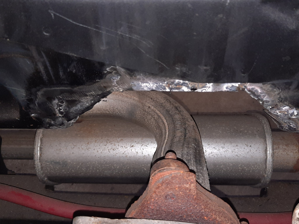
The first hurdle was insufficient down pipe to trunk wall clearance. While difficult to see, there was only about an inch of air gap.
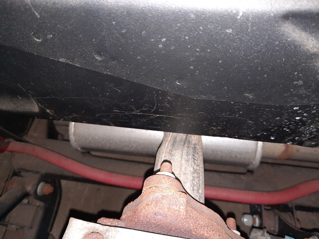
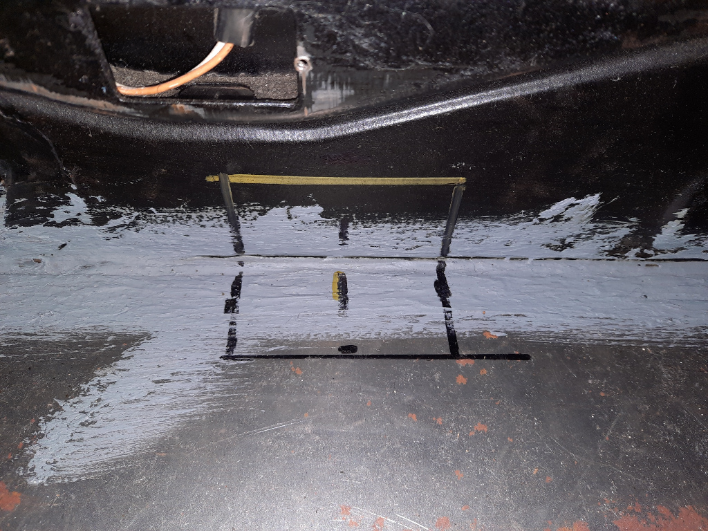
I marked the centre of the pipe and made a sufficient sized opening.
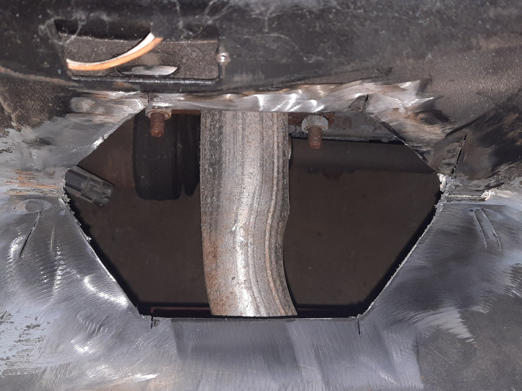
A few 16 gauge pieces were cut and this is the result.
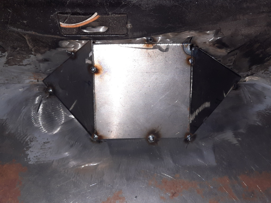
I only had a little seam sealer left in the can. So I used it all up.
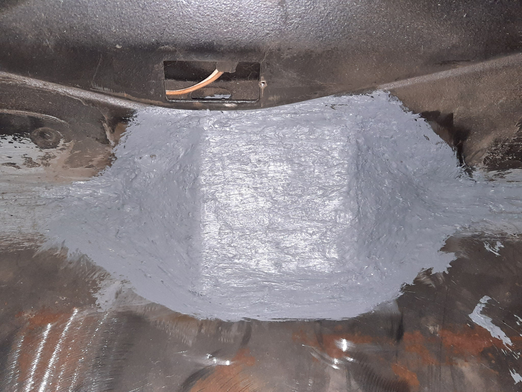
Since I had removed the exhaust in preparation for some post-process welding cleanup, the trunk underside was also treated to seam sealer and a coat of paint.
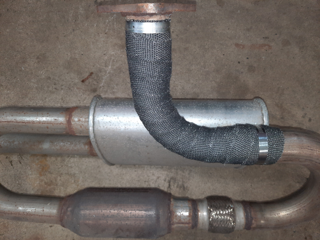
I had some left over exhaust wrap and applied it to the down pipe.
Okay, now onto some electrical/wiring.
As you've seen previously, I had all mechanical Equus gauges. I've since changed my mind and decided to go back to factory gauges.
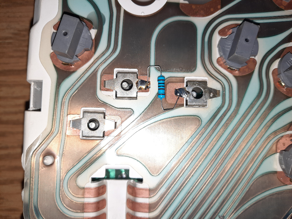
The factory tach will not work with the P11 PCM as is. It needs a pull up resistor to make it work.
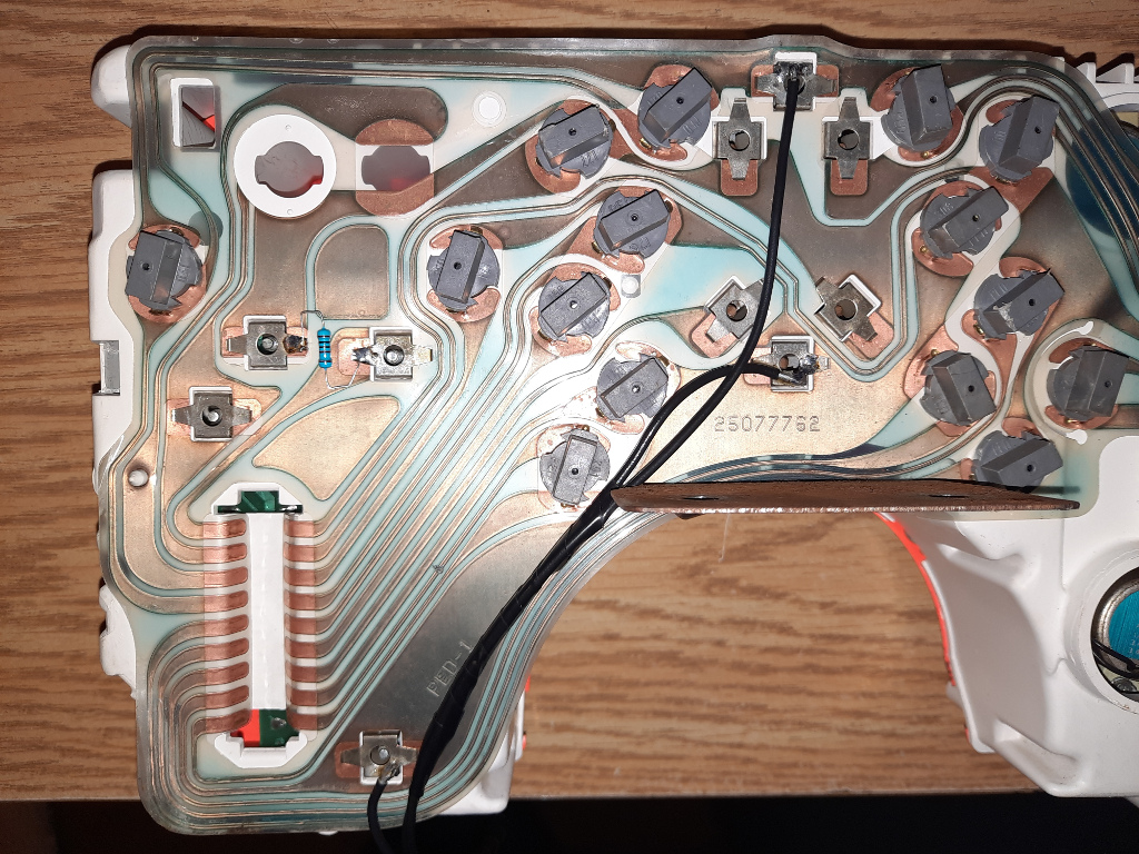
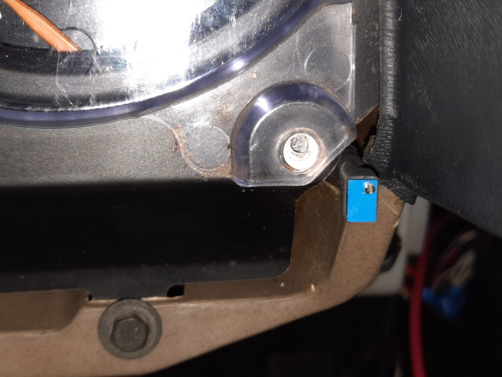
Now, on the back of the instrument cluster, just add in a 1K ohm (1000 ohm) as seen.
This provides switched power for the tach pull up signal. Yes, it's that easy.
My '84 gauges were kind of ugly and had a low redline. I had an instrument cluster from an '85 GT V6. I chose to use these as the redline was higher and the gauges looked better. After swapping out the six cylinder circuit board from the tach, I placed the four cylinder one in its place. This was the best course of action since it had the proper 0.1 uF capacitor in there.
I turned the key to on, and the tach settled on the zero mark. So far, so good. I then started the engine. While the tach was working, it sure didn't seem right. It was showing about 3-400 too high as seen from the live data stream on my scan tool. Okay, no biggie. Time to calibrate it. The tach was removed from the cluster and modified.
Measuring the resistance between pins 4 and 10 on the laser cut resistor, I had 277,000 ohms. I needed this in order to know what size of potentiometer I had to use.
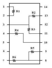
Note: Pin one is bottom left in the photo. Remember, it's upside down.
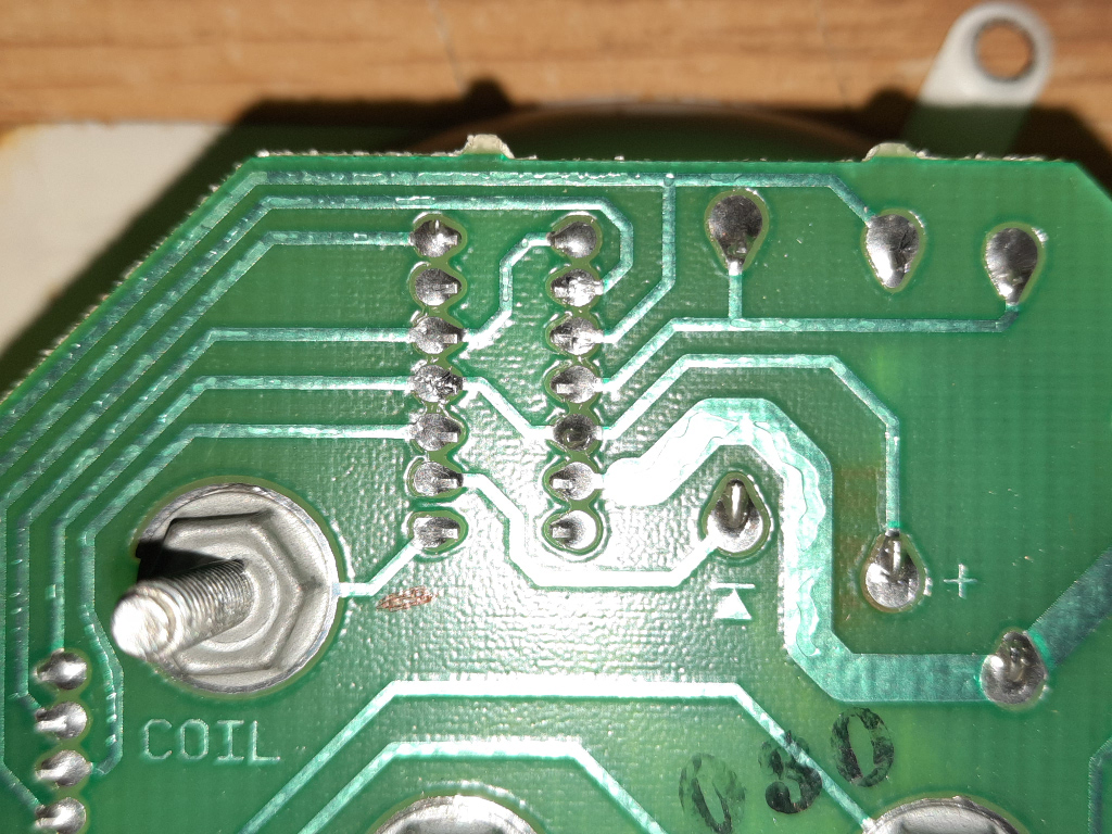
There is a small trace that I'm going to cut. While one could use a resistor in parallel with the factory original, I'd rather cut the old trace and use new components. Here is the offending trace that must be cut.
And here it is severed.
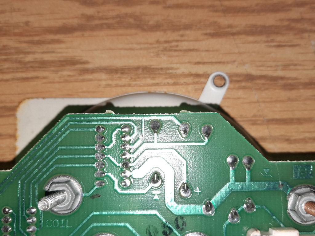
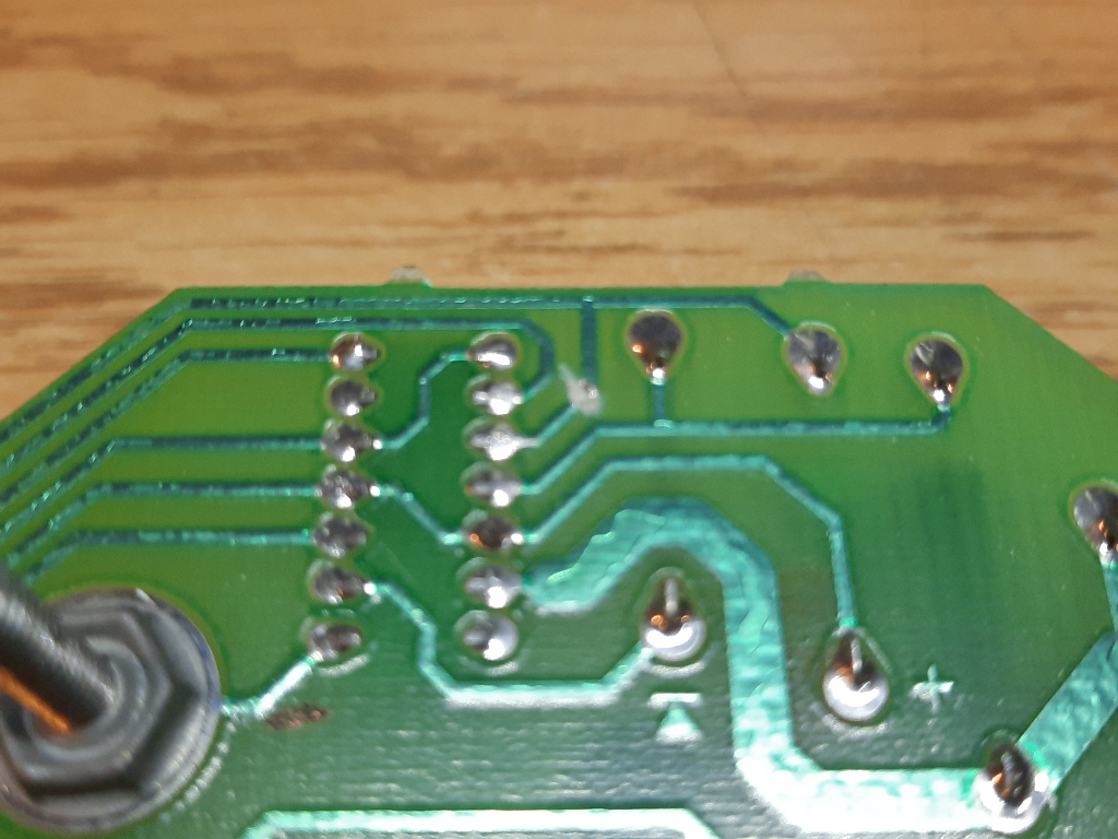

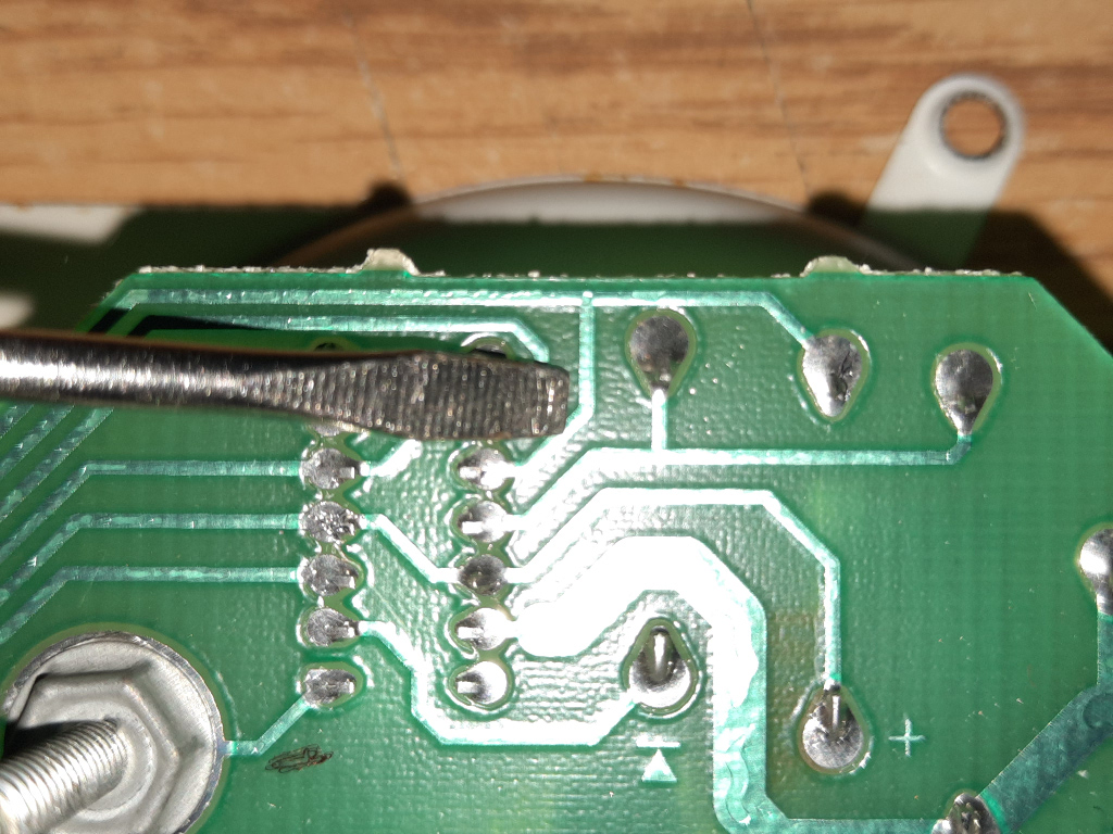
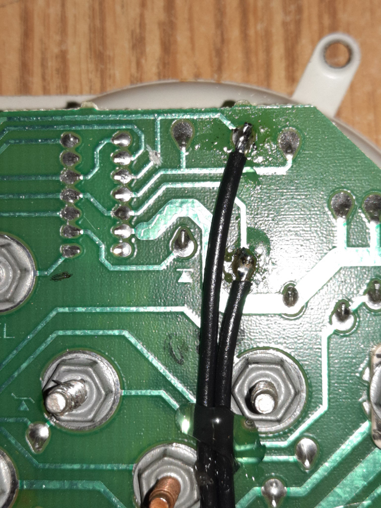
Two black wires were soldered to the two points as shown. This will allow me to remotely mount the potentiometer and make adjustments easier without having to remove the tach over and over. The tach went back together and the instrument panel was secured back in place.
As a side note: I had some flickering and dimming of the dash lights and some weirdness that comes from a poor ground. I cleaned the copper traces and ran a dedicated wire from three spring clips to a better chassis ground.
I looked in my bin and found a 1 Mega ohm trim pot. Albeit large in physical size, this will work perfect for my testing purposes.
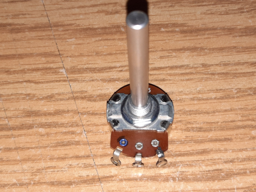
The engine was then started again. With having the live data stream showing RPM directly from the PCM, I then adjusted the trim pot accordingly. The tachometer was now calibrated to what the PCM was seeing. I verified at 1000, 2000 and 3000 RPM and back at idle. It was nice seeing it that accurate. Well, as accurate as it could be. They're never perfect.
The trim pot resistance was measured after the tach was adjusted. I ended up at 242,000 ohms. Now, I could find the proper resistor and solder it in. Or I could keep the trim pot in place. Due to its size, I wanted a smaller unit. I picked up a 7 mm unit for a few bucks at the electronics store. After soldering the leads to that one, I placed it just behind the bezel. If needed, future calibrations will be easy. Yes, it's tiny.
My PCM is mounted in the engine bay, attached to the trunk wall. This diagram is correct and my stock tachometer works as intended,
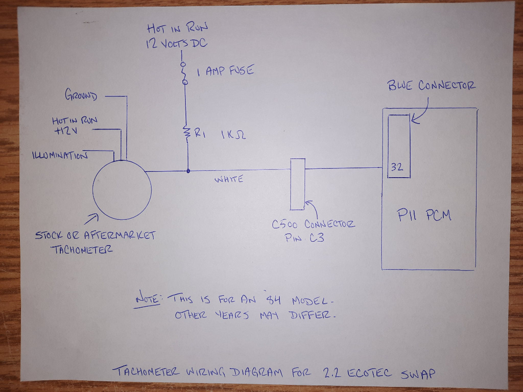
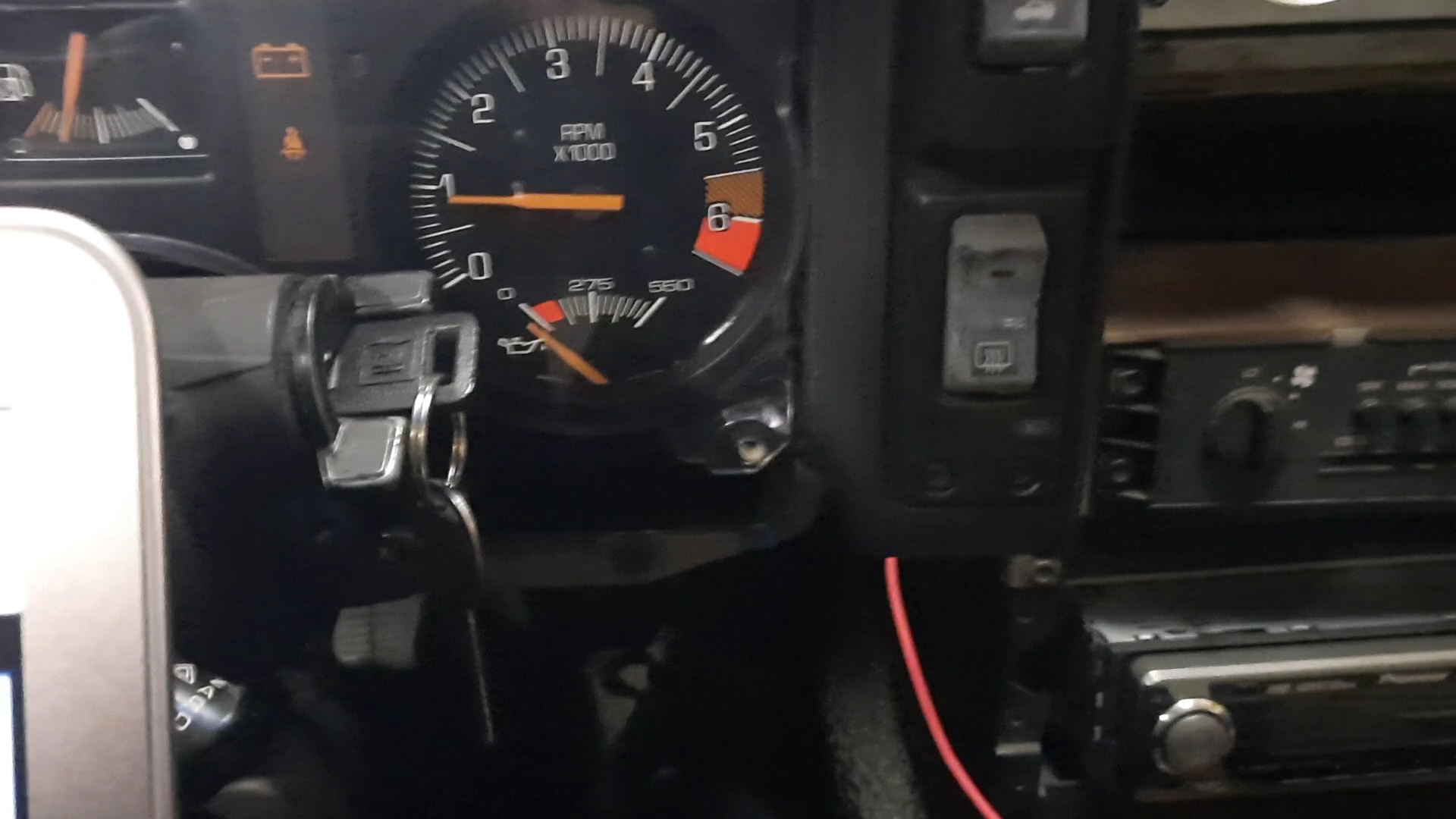
By using the above shown circuit and calibration technique, the video is proof of a P11 PCM feeding a Fiero tachometer correctly.
https://imgur.com/6VtGKNN[This message has been edited by Lunatic (edited 10-17-2022).]
|
|
|
|
Lunatic
|
OCT 17, 07:36 PM
|
|
Now onto making the speedometer function.
The P11 PCM has a speedo output signal on pin 34 of the blue connector. After a simple buffer circuit is made, and installed, the speedometer works as intended.
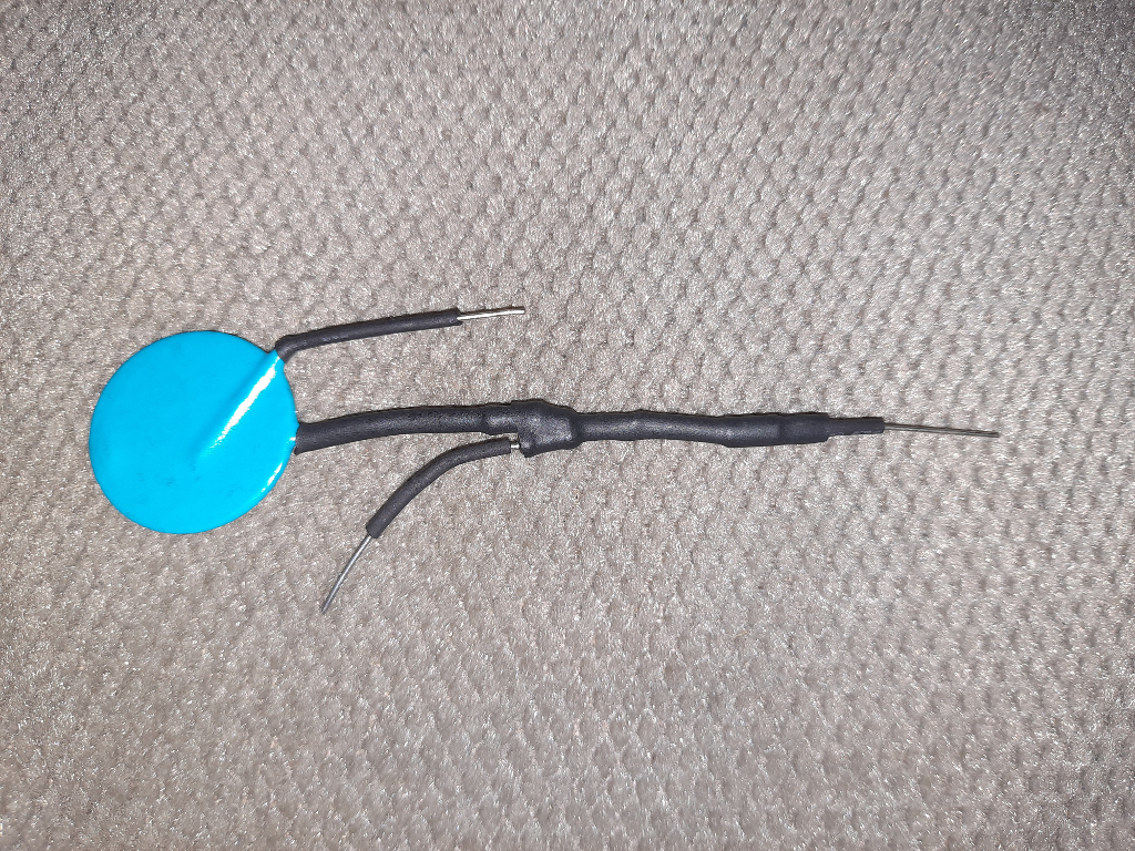
Using my diagram below, the buffer circuit was made.
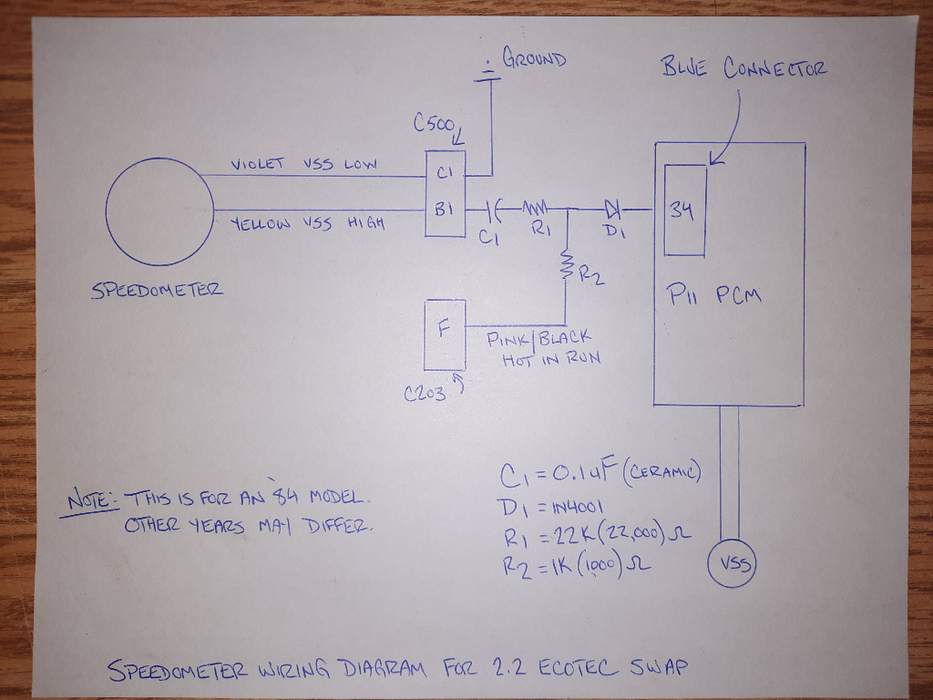
Here is the buffer ready to install.
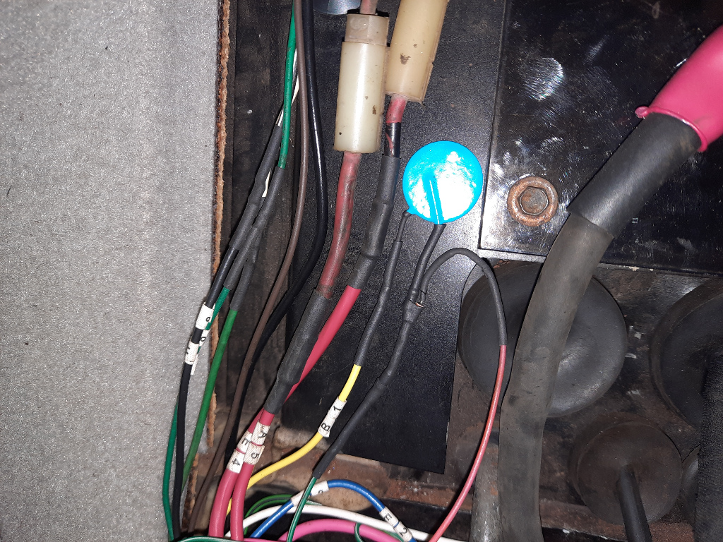
I placed it on the firewall in the location shown. I'll probably hot glue it place later on once I clean up and secure all the other wires.
Here is a small video showing the speedometer operational.
https://imgur.com/SCW0lpA
P11 PCM information.

If you're looking to do a stand alone Ecotec swap, whether in a Fiero or another vehicle, then following information may be of use to you.
My engine runs on the stock PCM. At this point, the only thing done to the PCM was VATS (Vehicle Anti Theft System), was turned off using HP Tuners software.
While I chose to install the BCM (Body Control Module), I only wired up the interior light control circuit.
The stock 12576162 PCM can run the Ecotec with the following subsystems removed.
-EBCM (Electronic Brake Control Module)
-Instrument panel cluster
-Inflatable restraint sensing and diagnostic module
-Passlock lock cylinder
-Radio
-Vehicle communication interface module
-BCM (Body control module)
This PCM has tachometer and speedometer outputs. As shown, they can be wired up easily in a Fiero.
|
|
|
|
wftb
|
NOV 02, 10:34 AM
|
|
|
Great work Shayne. That is awesome info for ecotec swappers so they can keep their interiours stock.
|
|
|
|