
 
     |
| A 3.4 DOHC Build then... F40 Turbo (Page 17/57) |

|
BV MotorSports
|
MAY 23, 04:51 PM
|
|
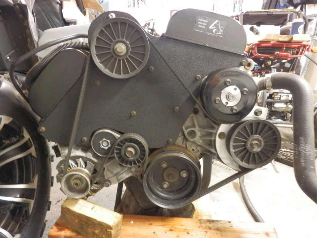
You know whats funny? Bobby Starcher & I came up with the metal timing cover way back in 2001 when we were working on Garth's LQ1 swapped 87. Nice to see it put to use all these years later! 

Here is ours:
|
|
|
|
Fierobsessed
|
MAY 23, 07:27 PM
|
|
|
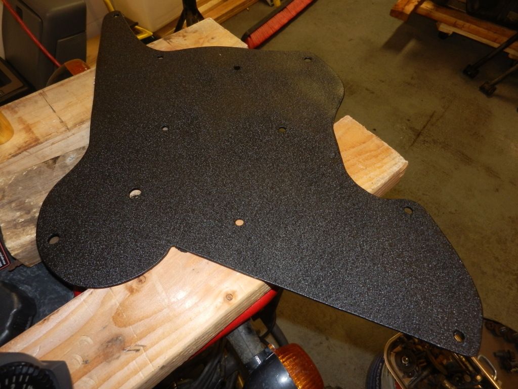
I'm not totally sure I'm going to use it just yet. I still have a plastic one in great shape. I bought this metal one from someone 9 years ago, I had it made 1/4" thick to help support idler pulleys for a supercharged LQ1 that never happened. I'd rather it was 1/8" thick for this application. I could have a new one laser or waterjet cut, but I'm a bit on the fence about it at the moment. The 1/4" one doesn't seal correctly to the upper timing sprocket covers without modification, and it just barely clears the belt. It still looks pretty though, but it is SO overkill.
|
|
|
|
BV MotorSports
|
MAY 23, 08:02 PM
|
|
|
I was wondering why yours was so thick. We used some foam rubber on ours where it meets the engine. Its been in use for 12yrs and 60k miles. We kinda had to come up wih something when the dog bone attachment broke the mount for the original pwr steering. We also relocated the dogbone down by the oil filter. Worked out pretty well. [This message has been edited by BV MotorSports (edited 05-23-2013).]
|
|
|
|
Fierobsessed
|
JUN 02, 08:19 AM
|
|
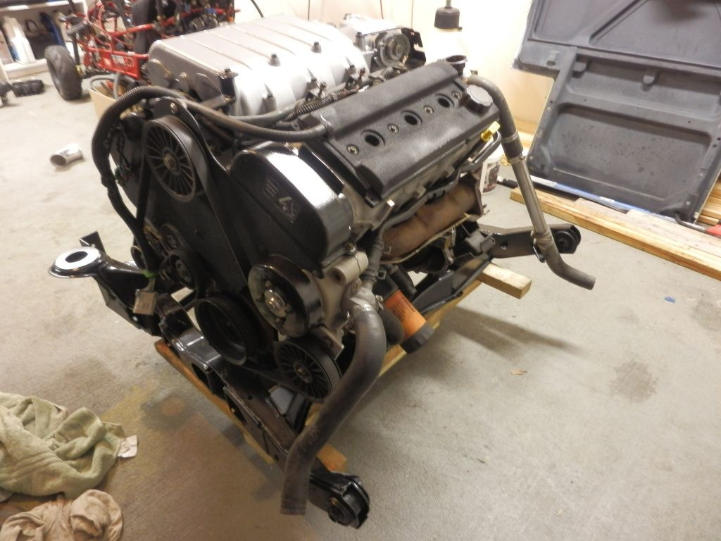
With the buildup of the engine nearly complete, I decided that I would forego the clutch and just assemble the engine and transmission and get to work on all the remaining stuff, mostly the smaller diameter plumbing that needed to be done.
Engine and transmission mated, without the clutch.

Landed on the cradle, Naked

Add clothing

I have got to say, When It's put together, its sheer beauty is reason enough to keep me plugging away at it

Now, with things back to their assembled state, I can begin working again. First up, fuel lines.
I started out with some 3/8" stainless tube, and after a couple of practice runs, I managed to bang out two fuel lines that navigate over the top of the turbo inlet.
When I was happy with them, I welded on the stubs from the original fuel lines that go into the fuel rail.

This is one of the more difficult types of welds that I've been doing. Its two VERY thin wall tubes, and they are being welded with a 1979, 700 LB 310 amp TIG machine, and yet, it's so incredibly accurate. It is a challenge though to keep the torch from blowing holes in these super thin tubes.
I also made some vacuum lines out of this same stainless 3/8" tube to operate the BOV and the PCV, a nice "T" weld was needed.

It'll go something like this...

Looking for a way to secure the fuel lines, I took advantage of my Shifter cable/turbo support bracket to now also hold the fuel lines, So I milled out a small block of aluminum to hold them in place.

Secured nicely!

I really love when I have the opportunity to turn a part in the lathe, and I found just that opportunity in plugging the cam position sensor hole. I loaded a piece of aluminum stock in the lathe, and just started turning away, mimicking many of the dimensions of the original sensor.

I then cut it off, turned it around and did some finishing work

All done

At this point, I turned my attention to both the turbo's water cooling lines, and the wastegate's water lines as well. Water cooling the wastegate according to the Tial, is optional on street applications, but recommended for racing applications. I figured what the heck, if I can find a nice way to do it, I would.
The 3.4 DOHC has a strange feature of its cooling system. It has a hot water outlet port from the thermostat cavity that directly feeds the throttle body in the intake manifold, and then dumps it back into the water pump inlet neck. What's strange about it, is that it closes off as the thermostat opens. Presumably it just allows water flow to circulate around the engine loop till it is up to temperature, then the thermostat opens, it will only circulate through the radiator. I decided, that since I would have had to rework the dump line from the intake back to the water pump inlet neck. That I would instead re-purpose it by running it through the turbo and wastegate In parallel, then dump it back into the pump inlet neck. I would then modify the thermostat so that it can no longer cut off the circulation to the throttle body.
So I changed out the 3/4" throttle body water line for a 1/2" fitting, and I put a better heater core barb on the intake outlet. They don't interfere with each other this way.

Next up, custom turbo water feed tubes.
|
|
|
|
Fierobsessed
|
JUN 03, 06:09 AM
|
|
| quote | Originally posted by Joseph Upson:
You may want to take a peak at Robertissar('s) nast1 8F code on the 60 degree forum for some more ideas. I haven't given it a try yet but it has higher resolution VE tables up to about 8200 rpm. I'm getting ready to switch back to code59 since I'm still having problems with spark blowout using code 8F that I don't believe I ever experienced with code59 when the compression was a little higher than it is currently. It could be something in the code but I have not been able to find it. |
|
Thanks! I've been watching some of his stuff, I like his work.
To your problem, my understanding is that this is not possible. The Ignition Control module interfaces directly with the crank sensor, and the computer only feeds it info on varying the timing a bit. The ECM cannot kill the spark to the best of my knowledge, only control it's timing. Even then, any timing issue will show up in the ALDL. Try monitoring L003D, Bit 3. If it goes high, all fuel is shut off, It's triggered by: Over-rev, Over-speed, VATS and Over-boost. If it's just breaking up, it could be a multitude of other things. Figured I'd throw something out for you to check.
|
|
|
|
Joseph Upson
|
JUN 03, 06:35 AM
|
|
| quote | Originally posted by Fierobsessed:
Thanks! I've been watching some of his stuff, I like his work.
To your problem, my understanding is that this is not possible. The Ignition Control module interfaces directly with the crank sensor, and the computer only feeds it info on varying the timing a bit. The ECM cannot kill the spark to the best of my knowledge, only control it's timing. Even then, any timing issue will show up in the ALDL. Try monitoring L003D, Bit 3. If it goes high, all fuel is shut off, It's triggered by: Over-rev, Over-speed, VATS and Over-boost. If it's just breaking up, it could be a multitude of other things. Figured I'd throw something out for you to check. |
|
Actually it appears it is so far. Robertissar teased out about 5 dwell related tables in my XDF and I adjusted two of them a little. Whether they work or not is hard to say as the day before I adjusted them the car ran as high as 9 psi, but that was with mild throttle input and below 4000 rpm after I installed the OE coils in the stock location compared to the MSD coils in a cooler location. After I made the adjustment the car again went to 9 ish psi with more aggressive throttle input but I could feel a little break up.
I delayed the alky injection a little more and hit 10.3 psi without any break up or blowout and it appears the alcohol injection may have been behind some of the blowout although I believe it was set to activate at appx 7 psi. I'll have to check but I suspect it doesn't kick in until 8 psi now. I'm also running a little more timing than I was able to previously with the blowout problem which is another sign that something between the changes has cleared up the blowout as I have not had it since the changes even with more timing and boost and above 4400 rpm. Normally it would blowout around 3500 rpm.
The dwell is determined based on certain inputs as I had previously read some months ago in a GM document so adjusting them to make a calculation during a more demanding load I suspect would help.
|
|
|
|
dratts
|
JUN 03, 11:31 AM
|
|
|
You guys are so far ahead of me on the technical end of this that the only thing I can contribute/say is HOLY COW! that thing is sure pretty. Congratulations, I think that I would want it in my living room so that I could look at it more often.
|
|
|
|
Fierobsessed
|
JUN 08, 12:30 PM
|
|
been working on the turbo/wastegate water lines.
I took my two water line kits, which were banjo fittings with 3/8" tubing. I cut the tubes down to about an inch, and welded on 4AN fittings to them.
Once that was done, I went ahead and bent up some 1/2" stainless tube to get the water to and from where it needed to go. I drilled the opposite side of the banjo's to 3/8" and welded the new 1/2" tubes to them.


The two 4AN fittings will each go to the wastegate. This way the water flow coming out of the throttle body will divide and either go to the turbo or the wastegate, and then rejoin and head back to the water pump inlet neck. The two hoses to connect the turbo water lines to the wastegate are on order, and should be delivered later on today. I also took one of the banjo fittings off the wastegate and cut off the 1/4" barb, drilled it out to an "R" drill, and tapped it with a 1/8" NPT, so I could screw in a stone filter, as this port will be atmospheric in this build.

I took the original throttle body return tube and cut it in half, then folded the edges down with a pair of pliars to close the opening down to 1/2". I welded a 1/2" stainless 90 bend and used a brass compression coupler to join the turbo water drain to this connection. I only put the coupler there for convenience reasons. Once the two hoses come in, I can say that the water lines are now complete.

Next on my list was the two O2 sensor bungs. One heated narrow band, and one Wide band. This was about as simple as it gets. I picked my location, just downstream of the turbo, slightly on the inside of the bend (because it's probably a little cooler there) and used a 7/8" hole saw, and slipped my two bungs in, and TIG'd them in place. I also ran a thread chaser through to clean up any distortion that may have been caused in the welding process.


Lately I've been putting a lot of thought into how I am going to do my breather/oil vapor recovery system. I am seriously considering integrating the turbo drain into that system too. It's been racking my mind a bit, mainly because I'm just about completely out of space. This swap is the tightest fit thing you can imagine, it's up to the point where I can say that I just don't have any place to put anything else. But nonetheless, I will seek a functionally convenient spot to put this device I have to design and build.
The reason I speak of integrating the turbo oil drain system is simple. Most people screw up their oil drains because they forget what is actually coming out of their turbo isn't really oil, it's mostly just air, and of course some finely misted oil, and a reasonable amount of hot liquid oil. The turbo has above atmospheric pressure going into every hole except the air inlet, and hopefully the oil outlet. So a bit of air coming out of the oil drain is expected. This air bleeds in through the seals, which helps keep the oil from going out those seals. So it is important that this air has little to no restriction on it.
This is the sole reason you should never have your turbo oil drain go into the oil pan below the level of the oil. All the air coming out of the drain would be restricted by the oil blocking its path. It would have to blow bubbles in the oil to drain correctly. This Is too much of a restriction. If the air was bled off right below the turbo, then the oil actually can be plumbed in below the oil level in the pan, and it would be okay. Not that this is my goal, I already come in above the oil level.
I am considering this concept of venting this turbo drain air directly from the turbo into an air/oil separator, that drains back the liquid to the oil pan. Also doing the same to the engine from a valve cover. Then I can just let the turbo's oil drain separately directly to the oil pan naturally by gravity. This will increase my drain lines capacity greatly by removing the airflow from it.
I've never heard of anyone doing this type of arrangement, but I see merits to be had, and it really isn't too difficult. But it's all theory till I actually build it, or for that matter even decide to go this route.
|
|
|
|
nitroheadz28
|
JUN 08, 01:11 PM
|
|
A work of art  
It would almost be a shame it install it in a car.
|
|
|
|
Fierobsessed
|
JUN 11, 05:42 PM
|
|
Thanks!
I got my wastegate water feed lines and installed them the other day, I'm pretty happy with them, but I will need a 90 degree swivel adaptor on one end of one of the lines. The bend radius was a little too sharp for my liking. But it looks good so far.

After much debate (in my head) I finally came up with a vapor recovery/breather tank design that not only am I pleased about, but that I will be making from scratch, with things I have on the shelf, So it will be cheap.
One of my priorities was to make it with a cover that is removable. I did a little layout in Autocad, and using the dimensions it kicked out. I milled the cover pieces out. This is the first time I have used my rotary table to do curved milling, and much to my surprise, it went extremely well!


I designed this cover to be used on the end of a short piece of 3" boost tube I had laying around from another project.

I found my spot to put it too, It's going to be wedged between the cruise control servo, and the boost pipe coming out of the turbo. Seems like the last spot I can fit something up high. I will try to find a way to allow it to drain into the oil pan. Possibly use the oil level sensor hole? I don't know just yet.
And another thing I had to do, was to come up with a Fiero slave to F40/F23 adapter. That didn't turn out to be that difficult at all. I might make a batch of these if I have time.

Just keep plugging along...
|
|
|
|


