
 
     |
| A 3.4 DOHC Build then... F40 Turbo (Page 16/57) |

|
Fierobsessed
|
APR 22, 09:02 PM
|
|
I started buttoning up the bottom end.
I cleaned the timing cover from my old engine. Surprisingly it didn't even need any paint. It survived 6 years of service and only needed a good cleaning. I installed the cover taking care to put sealant on the 4 M10 bolts that intersect the water passages. I then put the oil pan on. I needed to put a couple of small outward dents on the pan where the front mains studs were hitting, it was a very minor interference.

I tapped the head bolt holes a little deeper, I managed to get an extra 3 whole turns on the tap. This got the head stud length out of the block to 4.144". Now I don't have to worry about the studs hitting the cam carriers anymore.

Rumor has it that the 91-95 3.4 DOHC's are non interference engines, while the 96-97's are interference.
So I decided to run a little test,
I put a piston at TDC, put an intake and an exhaust valve in the head and put the head on. Then I could see how far the valve could move before hitting the piston.
I pulled the valve up to the seat, measured the stem height then zeroed out the caliper, Then I let the valves rest on the piston and measured the stem height.
Exhaust:

Intake:

The valve lift is .370" and the head gasket adds .055" of clearance. So at a minimum this engine was designed with .039" of clearance in a worst case scenario. So this engine is a clearance motor. And the valve reliefs are necessary to maintain that.
Next, I'll have to get the heads and clutch all finished up, and get this engine ready to go back on the cradle. Then it starts to get exciting.
|
|
|
|
Fierobsessed
|
MAY 10, 06:06 PM
|
|
After a little bit of a break, in which I was waiting for my heads and flywheel to come back from the machine shop, I'm back in full swing. I was on a side project during that time too.
As soon as the heads came back I started loading in the valve train from the 96-97 crate engine into those 91-95 heads.


Gaskets in place.

All bolted up

Cam carriers on and TORQUED this time. Getting ready to do timing.

Belt loaded, timing wheel, marker and disk set on TDC

I made a tool, its 3/4" by 0.895" by 3" aluminum block. I decided to use this in place of the standard timing setting tool that sets both cams in straight up at TDC.
All I need to do is place it on top of the flats, and when it is even with the top of the cam carrier itself, the cam is straight up. This way I do one cam at a time, and set the timing on them to whatever I want.


I took the covers off the end of the cam carriers to allow me to manually turn the cams.

So all I had to do was set the crank where ever I want the timing to be, then place the tool on the cam, turn it till its square with the carrier, then lock it down.
I set the exhaust cams to be even at ZERO, so they are straight up. I retarded the intake cams 5 degrees. This should lower the engines peak torque RPM, and help with turbo spool. At least in theory.
After I had all four cams locked down I did a test, where I put the tool on the cams and rotated the crank till the tool was flat with the cam carriers, WITHOUT looking at the crank degree wheel. This is how I confirmed the timing was as I wanted it. and everything was bang on within a degree. I then checked that the degree wheel was correctly indexed on TDC again. This way I absolutely know everything is as intended.
Timing is done!
I also sand blasted the intakes, and the valve covers, I decided that I am going to have them powder coated. I had too many problems painting them to justify powder coating, with the money made on the side project.
I'm getting excited about this project coming along.
|
|
|
|
Fierobsessed
|
MAY 15, 01:10 PM
|
|
keeping it simple for today. I blasted and painted my exhaust manifolds and heat shields, and installed them, as well I painted the lower intake, installed it and the Siemens Deka 60 lb-hr injectors. They fit beautifully.


For the huge injectors that they are, they are quite small. I've always found that to be a bit ironic.
It's more waiting for me, my clutch isn't back from Clutchnet yet  and I'm sure it will likely be a day or two more till the intake and valve covers are back from powder coating. So once again I am stuck waiting. I'm looking for little details to iron out while waiting. I know I have some plumbing to do, I need to balance my flywheel, and paint a couple things. But really, there isn't a whole heck of a lot of work left to be done. And at the moment I don't want to even think about dropping the tank. It is my absolute least favorite activity to do on a Fiero. I'd rather replace a throttle cable then drop the tank and I'm sure it will likely be a day or two more till the intake and valve covers are back from powder coating. So once again I am stuck waiting. I'm looking for little details to iron out while waiting. I know I have some plumbing to do, I need to balance my flywheel, and paint a couple things. But really, there isn't a whole heck of a lot of work left to be done. And at the moment I don't want to even think about dropping the tank. It is my absolute least favorite activity to do on a Fiero. I'd rather replace a throttle cable then drop the tank 
|
|
|
|
sleevePAPA
|
MAY 15, 09:11 PM
|
|
Nice! looking forward to seeing the car once its on the road
|
|
|
|
BV MotorSports
|
MAY 18, 08:38 PM
|
|
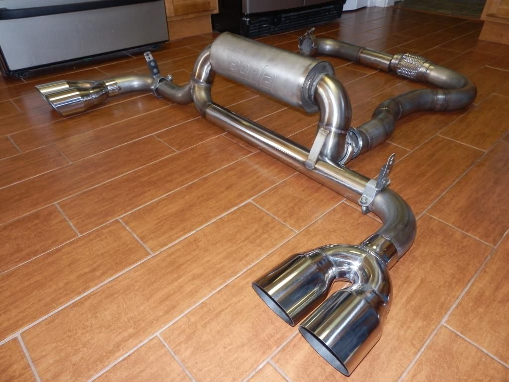
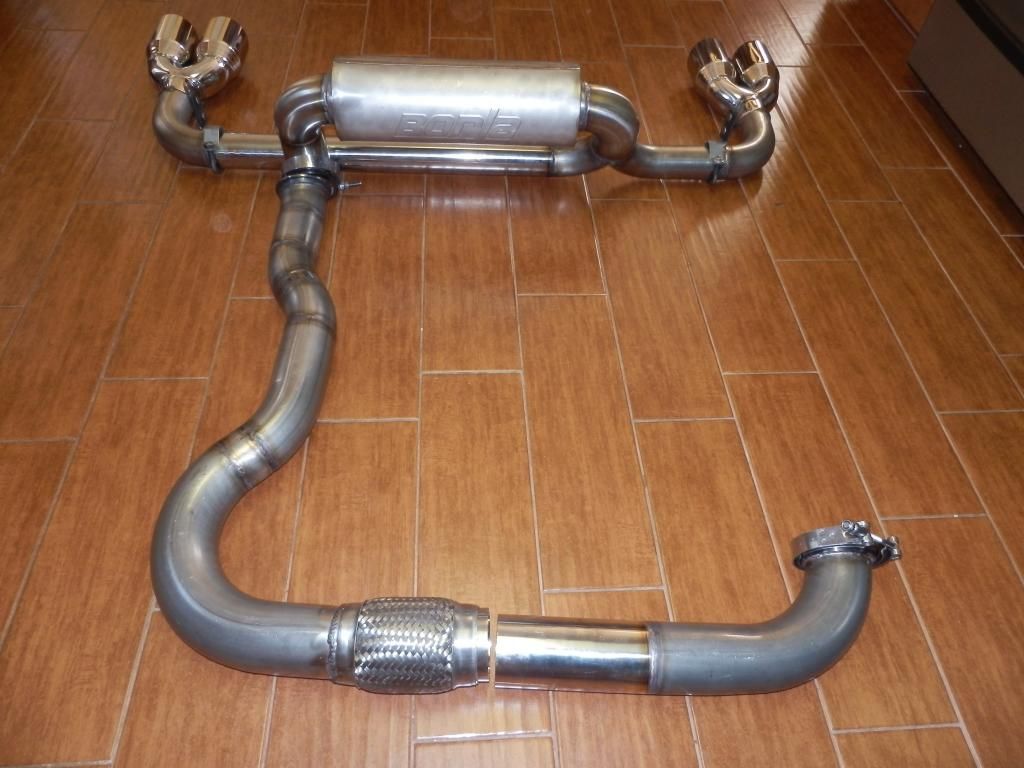
I cant thank you enough for duplicating your exhaust for me. Its one of my favorite parts of my build. I seriously think that with your fabrication skills, you could offer some TOP SHELF parts for Fieros. Again, thank you so much!!!!!!!!!!!!!!!!!!!!
 ------------------
2009 G8 GT Kook's 1 3/4 LT's, Kooks catted Xpipe, Magnaflow axleback, Vararam CAI, HSRK, HPTuners, Atari gauges
1988 Fiero GT L67, PT67bb, w2a, F23, & more
1987 Fiero GT 3.4TDC Road Racer.
ƒ13r0'$ rµ£3

|
|
|
|
sleevePAPA
|
MAY 18, 10:44 PM
|
|
|
WOW
|
|
|
|
Fierobsessed
|
MAY 19, 06:26 AM
|
|
|
I'm glad you are happy with it, If you have any questions about installation don't hesitate to ask.
|
|
|
|
BV MotorSports
|
MAY 20, 11:15 PM
|
|
| quote | Originally posted by Fierobsessed:
I'm glad you are happy with it, If you have any questions about installation don't hesitate to ask. |
|
I'm not happy with it at all. I am ecstatic!!!!!! Maybe on of these days I'll get around to installing the exhaust. I am too busy showing it to all my friends when they visit. Everyone that see's it say its too pretty to hide under the car. Man, We need to get you to start making headers, y-pipes, turbo manifolds, exhaust's etc.  I'll take your first set of LQ1 headers & y-pipe in the stock Fiero routing. Make sure it clears the Izuzu shifter cables. Garth says he wants this same exhaust but for his '87 LQ1 GT. I'll take your first set of LQ1 headers & y-pipe in the stock Fiero routing. Make sure it clears the Izuzu shifter cables. Garth says he wants this same exhaust but for his '87 LQ1 GT.
|
|
|
|
Fierobsessed
|
MAY 23, 05:51 AM
|
|
Some good news for this morning, Got a call from the powder coaters letting me know that they just pulled my pieces out of the oven, and to pick them up in a couple hours. 
So I picked them up and snapped just this one photo of the front valve cover

I had to wait the whole agonizing day to get home from work and place the valve covers on and the Intake manifold, but when I finally got home I got right on it.


I am much more pleased about how the valve covers came out then I am about the intake. The valve covers are a very smooth casting while the intake is fairly rough so the powder coating has a bit of a texture to it on the intake. Makes me wish I had smoothed it out beforehand. But it's done and it still looks pretty good.
I've been keeping busy cleaning and painting everything. I rebuilt a 3800's gear reduction starter, cleaned and painted what needed it. I also attacked the alternator, Water pump pulley, the EGR valve and it's mount, as well as the transmission, it's brackets, the mounts, and the cradle. Just rebuilding, cleaning and painting. So that's been a bit of busy work.
Heres the starter, the oil cooler plumbing, and the turbo drain. You can see here why choosing the drain location was a bit tight.

Transmission

Turbo/shift cable bracket, and front transmission mount

I'm getting kind of frustrated with Clutchnet at the moment. I've E-mailed them, and called them with no response. They've had the pressure plate in their hands for well over a month, and not one thing, no pressure plate, no call, no E-mail. I've heard they can be a pain in the butt when it comes to customer service, but as of now, it has become a problem. It took a week or so to get it to me in the first place, so why a month + to repair it?
I'm going to go ahead and mate the engine and transmission, work on some of the smaller but critical stuff, like fuel lines, vapor catch system, heat shields, intercooler plumbing, heater line plumbing and so forth, and tear it apart to install the pressure plate when it arrives. But I am a bit frustrated about it. 
Other then that, I think it's coming along beautifully. I've also been working on a huge swath of improvements on the $8F code, specifically to make it work with my setup, and to make tuning easier.
I've added Digital EGR functionality
I've removed the Adder table, and expanded the main VE table to tune easier in the N/A range (17X13), Boost is still a multiplier, I'm more then okay with that.
I've added in A/C pressure transducer instead of the A/C pressure switch, and added code that set a pair of threshold values that are used to mimic the old switch.
I also added two additional MAT sensors, one for intake air temperature, and one for after the turbo. The stock one is located post intercooler, I might have to put it inside the intake manifold, but I'd sooner like to put it near the throttle body inlet. These new sensors are programmed to only report to the ALDL for logging.
I've added wideband logging, much like the IAT sensors, so that it reports to the ALDL.
I've added someone else's tweaks to help with manual transmission adaption.
I promise that when I am done with this code and all tuned in, I will make it available. Who knows what kind of bugs I'll need to iron out of it first. I've been using TunerPro V5, and heavily reworking the definitions, and adding patches for all the new functionalities.
|
|
|
|
Joseph Upson
|
MAY 23, 07:05 AM
|
|
|
You may want to take a peak at Robertissar('s) nast1 8F code on the 60 degree forum for some more ideas. I haven't given it a try yet but it has higher resolution VE tables up to about 8200 rpm. I'm getting ready to switch back to code59 since I'm still having problems with spark blowout using code 8F that I don't believe I ever experienced with code59 when the compression was a little higher than it is currently. It could be something in the code but I have not been able to find it.
|
|
|
|

