
 
     |
| Ecotec, Fastback, T-Top Build. (Page 12/22) |

|
Lunatic
|
MAR 15, 07:31 AM
|
|
Okay, I'll admit, I've been a little slack. February indeed was way too cold to be out in the garage. But now, I have some motivation again.
I cleaned, flushed, inspected and pressure tested the stock dual-core radiator and it passes my inspection.
I also picked up a new rad cap to accent the now clean and ready-to-install rad.

After inspecting my old clutch master, I decided not to reuse it. Instead, thanks to Netcam, I just bought his new one. (I think it's a unit from Rodney Dickman).

I wanted a complete polyurethane bushing kit to replace my worn out OEM bushings. This was easily accomplished by placing an order through the Fiero store. Very quick shipping too, three days.

That leaves the ball-joints. Well, the 88 upper is made of unobtanium and cannot be found locally (in Canada). Instead of finding something dimensionally close, and making it fit, I chose to place an order with Rodney Dickman.

New upper and lower ball-joints, steering rack bushing, new rear upright through bolts and tie rod end boots. Again, package arrived fairly quickly at my door in only four days.

Since I'm refreshing all the old, worn out parts, it only makes sense to get all new grade 10.9 hardware for the suspension.

Even though I have some new parts and I'm excited to install them, I still need to maintain the rest of the fleet for the upcoming season. I need to move to a planet that has 36 hours in a day!
PS-Upon opening a shoe box full of oddities, I found something....

 [This message has been edited by Lunatic (edited 03-15-2015).]
|
|
|
|
Lunatic
|
MAR 22, 04:54 AM
|
|
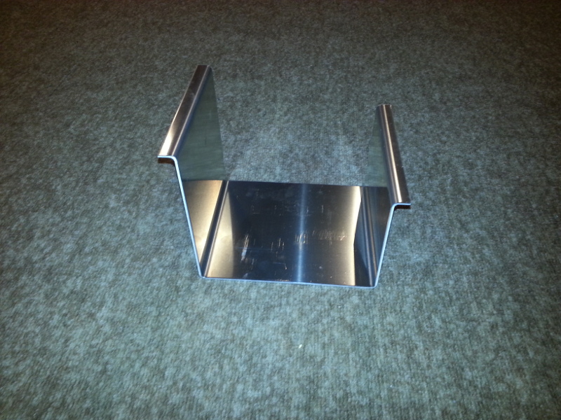
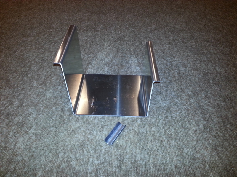
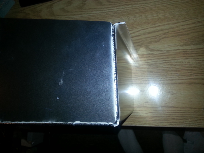
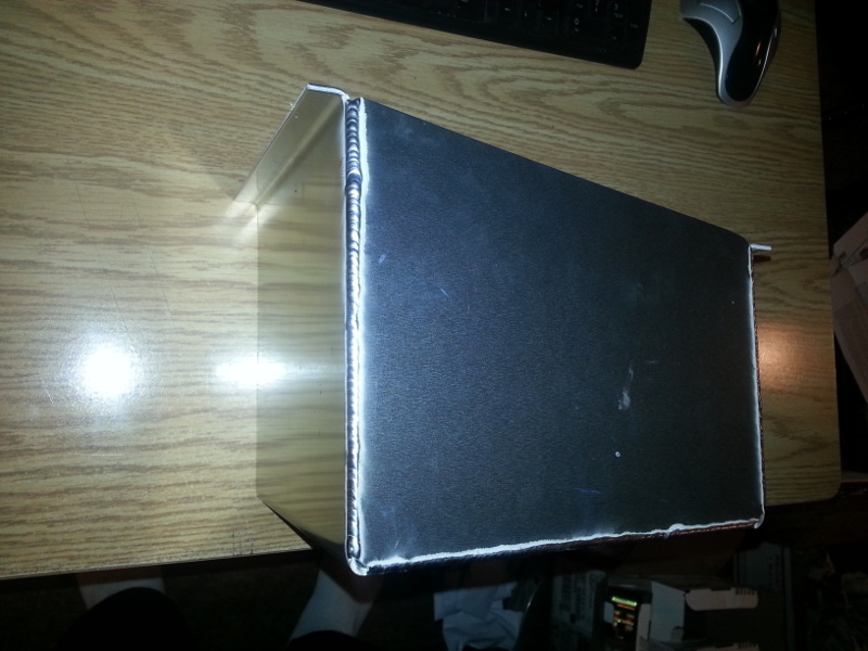
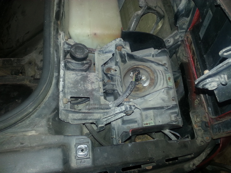
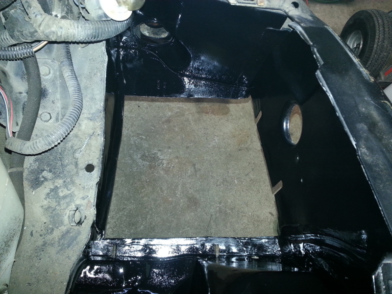
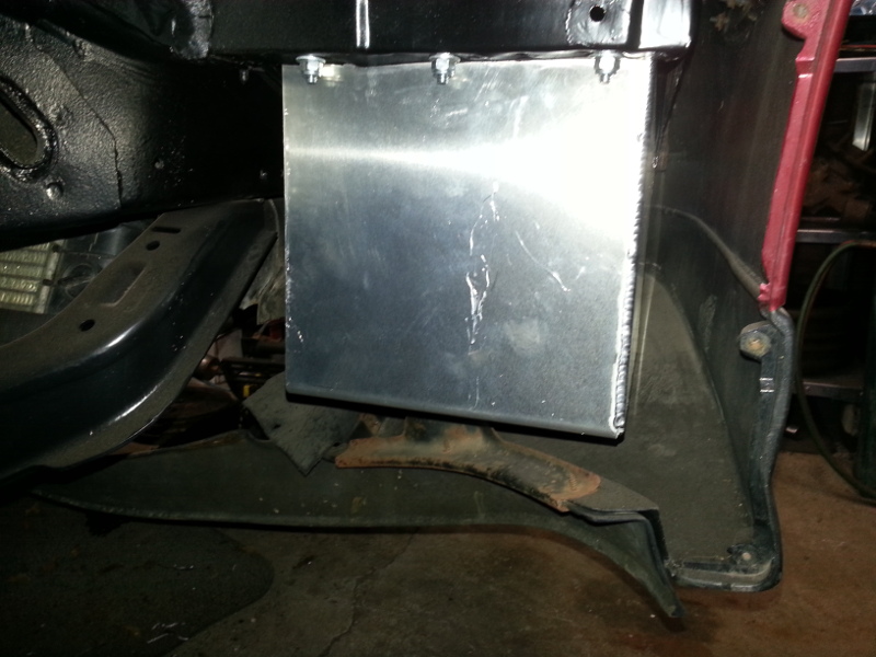
I'm aiming for a clean engine bay. With having said that, the battery will be relocated to a better area. What better way than to move it under the passenger side head lamp. This consists of making a battery tray, removing the area under the headlight and bolting in the tray. I used 1/8" aluminum for this project and yes, the stock battery hold down bracket will be reused, it's not shown in the photos though.
Note: I'm using the GT fascia. (This battery box will be hidden by this fascia). Non Aero cars might not be able to get away with this mod as the battery may interfere with the plastic.
Passenger side head lamp assembly.
After removal.
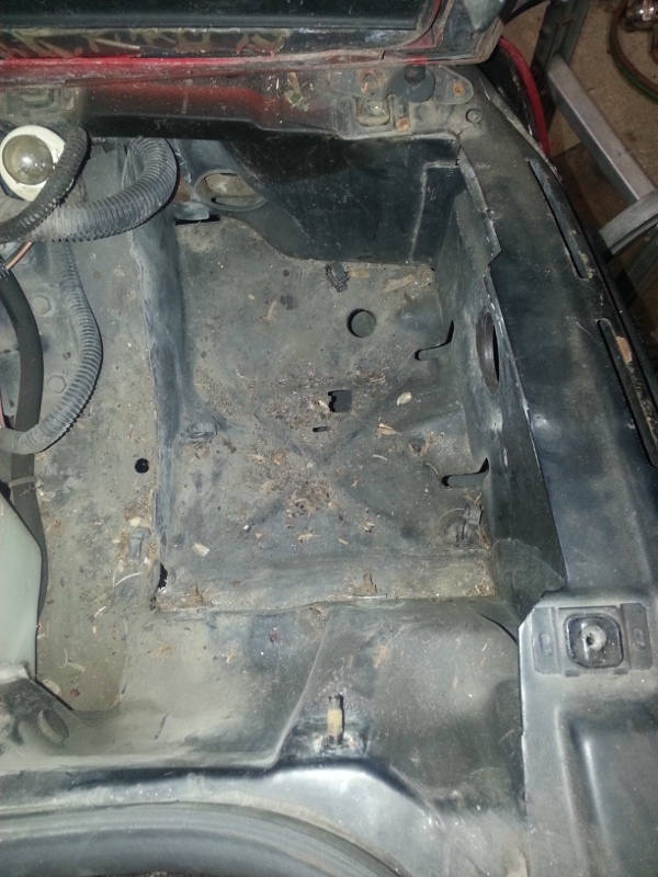
Cut the sheet metal and you're left with a hole.
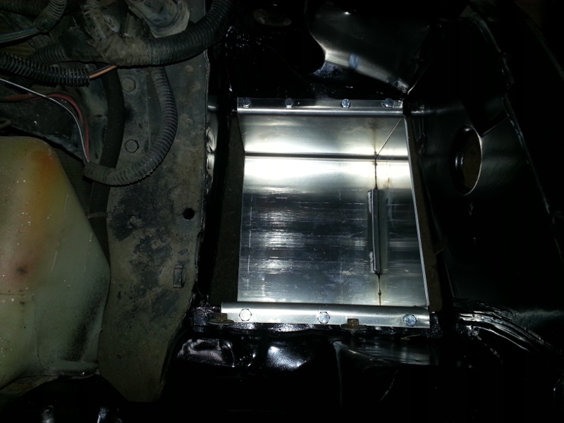
Trim these two studs a little as they interfere with the battery box flange.
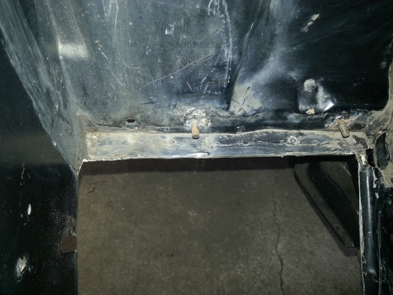
Now is a good time to paint the area since it's exposed.
Secure battery box with 1/4" hardware.
|
|
|
|
RCR
|
MAR 24, 06:21 AM
|
|
Great stuff. I'm curious how low your battery sits, and if you will still have room on top for the headlights.
I thought I put mine pretty low and I had no intent to put pop-up lights back in, but since my project took a different turn, I'm looking to put the pop-ups back in and fear they won't fit now.
How do you plan on servicing the battery if needed?
Bob
|
|
|
|
Lunatic
|
MAR 24, 06:34 PM
|
|
| quote | Originally posted by RCR:
Great stuff. I'm curious how low your battery sits, and if you will still have room on top for the headlights.
I thought I put mine pretty low and I had no intent to put pop-up lights back in, but since my project took a different turn, I'm looking to put the pop-ups back in and fear they won't fit now.
How do you plan on servicing the battery if needed?
Bob |
|
Thanks for commenting Bob.
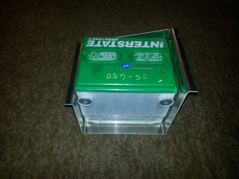
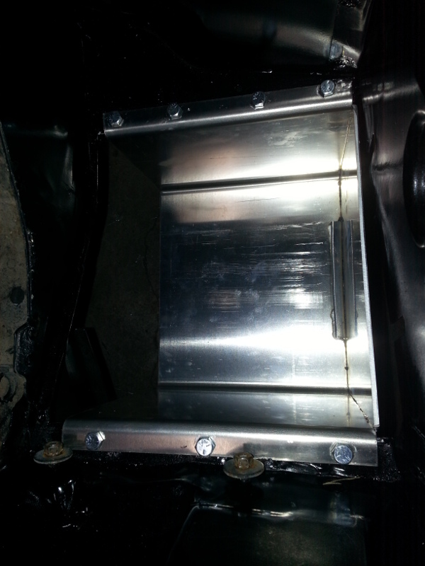
From the floor of the battery tray to the lowest part of the headlight assembly (in its lowest, parked position) is 8 3/4". My battery is 7 3/8" in height. Therefore I have 1 3/8" of clearance.
As for servicing the battery, I'll look into a quality unit that needs little maintenance. Perhaps a sealed unit from Optima. Either way, it's only a few minute job to remove the headlamp assembly if needed.
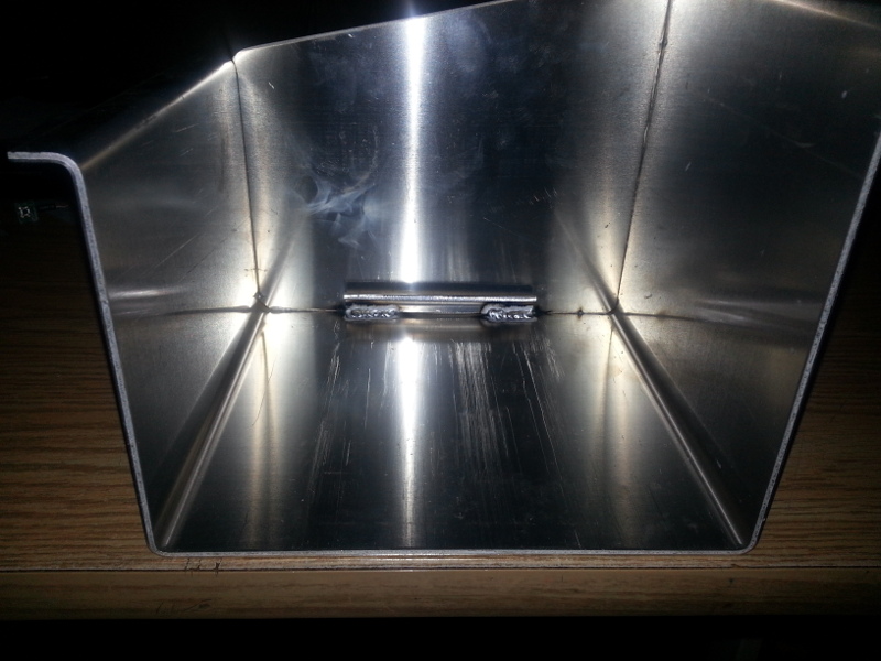
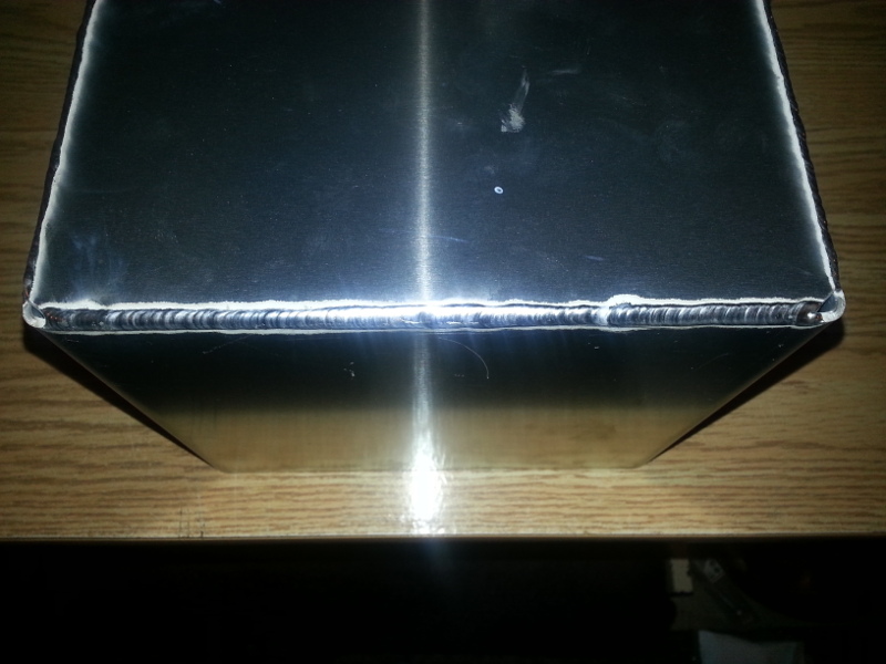
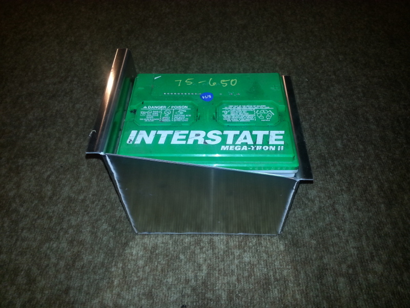
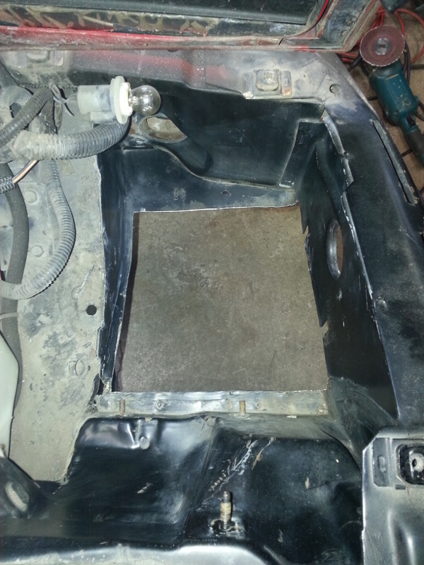
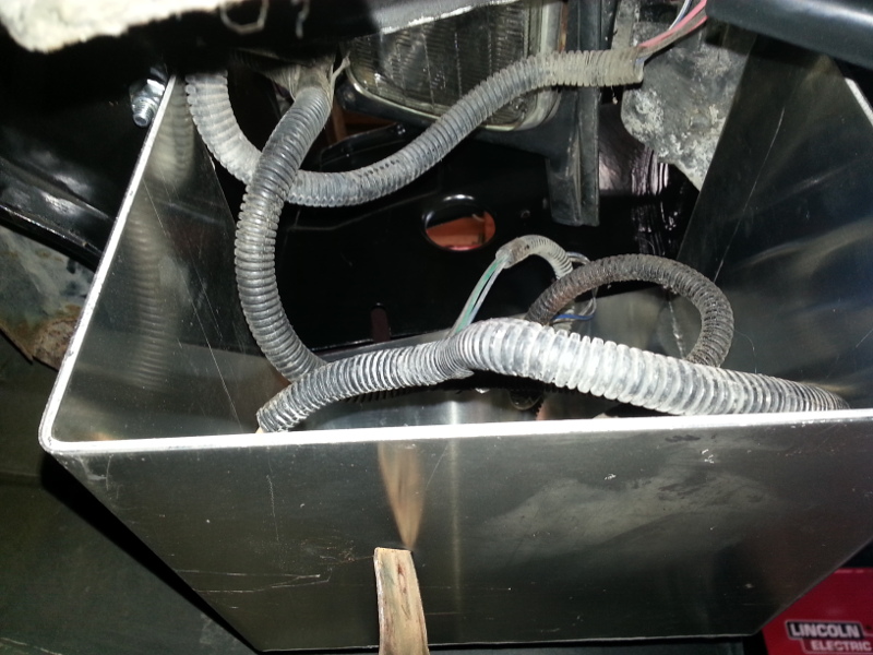
Here's two more pictures.
Despite not showing the battery in position, here you can see the clearance.
If I remove the curved steel from the bottom of the fascia, I can bolt that area to the battery box. (That should be a good indication of how low my battery box sits).
 [This message has been edited by Lunatic (edited 03-24-2015).]
|
|
|
|
RCR
|
MAR 25, 06:01 AM
|
|
Thanx for the extra shot. Much appreciated.
Bob
|
|
|
|
Lunatic
|
APR 30, 05:39 AM
|
|
Although April was very busy for me, I did manage to get some things done on the car. This time, the front of the car got a little attention.
Since I had used parts, they must be disassembled, cleaned and inspected before going into service.
88 rack disassembled, cleaned, inspected and painted.

Clean parts and new brass bushing.

Stake the inner tie rod. (You can also see the generous amount of grease).

Brass bushing correctly installed, more grease and yes, I painted the rack while it was apart.

The brass bushing, when installed correctly, sticks out 8 mm as seen. I used 3 rivets 120° apart to secure the bushing.

Index marks for setting the pinion tension.

Bellows and rubber mounts installed on the now clean rack.


Painted the rack hold down brackets.

I removed the spare tire tub for better access.

See, more room.

88 specific steering shaft.

This flexible cover from the 84 doesn't fit the 88 intermediate shaft because of the rag joint. I'll have to look into finding the correct one.
Anybody have one to sell?

Rack installed. The original nuts on the backside of the crossmember were missing. I chose 3/8"-16 x 1" zinc plated with Nylock nuts.
Note: You can get a wrench on the back side to hold the bolts from turning.

Since the factory shop manual, nor Rodney's instructions mention the torque of nut #7, I'm going with the 28-40 ft-lb scale since it's an M10x1.5 nut.
Exploded view from FSM.

For those of you that are interested in the installation of a larger brake booster on your Fiero, this is for you. It's not that difficult to do, really. Follow along if you will.
Note: Some use the 96 S10 booster for this mod. I used a 1995 Suburban booster because I had it. It's an 11" dual diaphragm design. It also has studs that make in easy to bolt the Fiero booster bracket to.
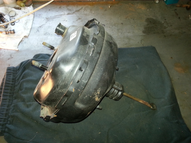
Remove the old booster from the car. You can actually move the brake master out of the way, leaving the brake lines intact. You'll have to remove the little screw that holds the proportioning valve in place. Once this is done, unhook the booster pushrod from the brake pedal, remove the four bolts from the booster, and place it on the bench. We need some parts from the stock Fiero booster.


Note the pushrod length. This unit is longer and will be reused in the larger booster. Yes, it's a direct swap.

This is the bajonet fitting. You'll see there are a few places that are staked. These need to be unstaked. Using a screw driver makes this easy.

Here is what it looks like unstaked. Do this on all the area's needing it.

Place the booster in a vice as shown. (Use aluminum angle on the jaws of the vice to protect the threads).
We're going to rotate the housing around 1/16th of a turn. It does have a spring in there and it will fly apart.
Prepare yourself and get a helper to hold down the top of the booster while you rotate.

Disassembled, this is how it looks.


In this photo, you'll need to remove this lock clip.

Exploded view.

Look way down and you'll see a circlip. Carefully remove this.

Pull out the pushrod like shown.

This is what you need.

Now, cut the bracket off the Fiero booster. We'll reuse this on the new booster.

This is the bigger 11" booster.
Like you did with the Fiero booster, take the new one apart the same way. You can see the different length pushrods between the two.
The Fiero pushrod is the longer of the two. This is what we'll be using in the bigger booster.

Circlip, pushrod and seal.

Insert pushrod into bore of new booster.

Circlip sitting on top, ready to be installed.

Circlip properly seated.

Retainer, spring and seal goes on.

At the top, you can seal the simple lock ring.


Turn the booster around and install the plastic guide.

Next the spring retainer goes on.

Now the spring.

The front of the booster now gets installed. Compress the spring, and rotate slightly to lock in position.

The studs are too long in my opinion. Cut them to aid in the installation.

The stock Fiero plastic sleeve, on the right, is reused.

Use new nuts with the Nylock insert.

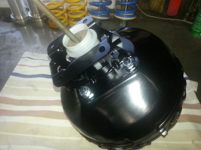
Bolt the Fiero bracket that you cut off earlier. I painted mine to match.
You will have to clearance for the bigger booster. Several judicious blows of a hammer in the offending area take care of this.

Add some paint.

Install the newly modified 11" booster.
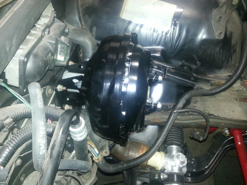
Reattach the master cylinder and enjoy! See, easy.[This message has been edited by Lunatic (edited 05-12-2015).]
|
|

|
zkhennings
|
MAY 08, 04:02 PM
|
|
|
Very nice work, did you pioneer the booster guts swap? Impressive. I should be picking up an L61 in the near future...
|
|
|
|
Lunatic
|
MAY 12, 05:30 AM
|
|
| quote | Originally posted by zkhennings:
Very nice work, did you pioneer the booster guts swap? Impressive. I should be picking up an L61 in the near future... |
|
Thank you for the compliment. Although I've swapped a few booster push rods out in the past, not only on the Fiero but on other GM vehicles, I'm certainly not the pioneer.
Phil documented this at one time on his Fiero. You can read about it here.
I hope to see a build on your L61 in the future.[This message has been edited by Lunatic (edited 05-12-2015).]
|
|
|
|
Lunatic
|
MAY 12, 05:40 AM
|
|
And today, the rear window gets re-installed.


|
|
|
|
Lunatic
|
MAY 23, 03:51 PM
|
|
Moving forward, I was eager to get the front suspension reinstalled. I took the stock 84 springs and cut 1.5 coils off both springs. I used an angle grinder with a thin cut-off wheel. Yes, you could also use torches but let them cool naturally and do not quench them in water! Then followed a visit to the sandblaster to remove years of crud. Then a little paint.


Cleaned the outer tie rods since they were in great shape.

A little paint and new boots, and they're ready to go.

The stock front 88 sway bar bracket has a little slope to it.

Stock bracket on the left, aftermarket one, with poly bushing on the right.

Reassembly begins.


At this point, I decided to make my own flex lines and take a break from all the paint fumes.
This was relatively easy to do as I've done it before on my motorcycle. Having left over material from that endeavor, all I needed was the fittings. The local speed shop had these. Anyhow, here's the end result.
The lines I've seen for sale were all around 18" long. I didn't like that length as it seemed a little too short for my liking.
So, I chose to make mine 24" long.
TFS line on top, mine on the bottom.


I like to finish off the end by putting heat shrink tubing over the outer casing.


Since the finish on the 18" wheels was in sad shape, the sandblaster makes short work of removing all the old powder coating. Now they're ready for some colour! Off for coating next week.

Oh yeah, a 2002 Northstar dropout was in the classifieds. It ended up following me home. You never know when I'll need it.

|
|
|
|