
 
     |
| The White Bug (Page 41/46) |

|
pmbrunelle
|
OCT 08, 06:24 PM
|
|
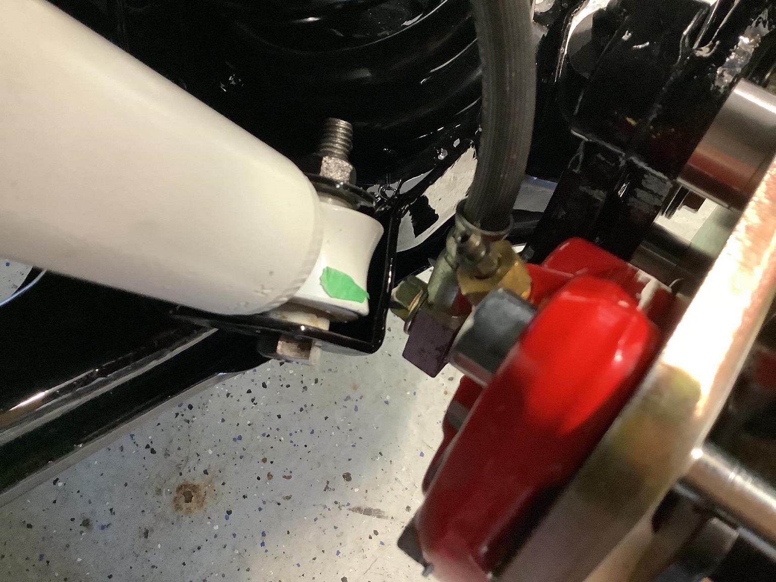
With the Wilwood 120-11872-RD calipers, the banjo bolt hits the damper mount on the LCA, at full droop / full lock:
To address this, I started by reducing the head height of the banjo bolts, but that wasn't enough.
The Wilwood caliper I have is actually made for a 1.04" thick rotor, so with the 0.87" thick LeBaron rotor, the caliper is excessively wide.
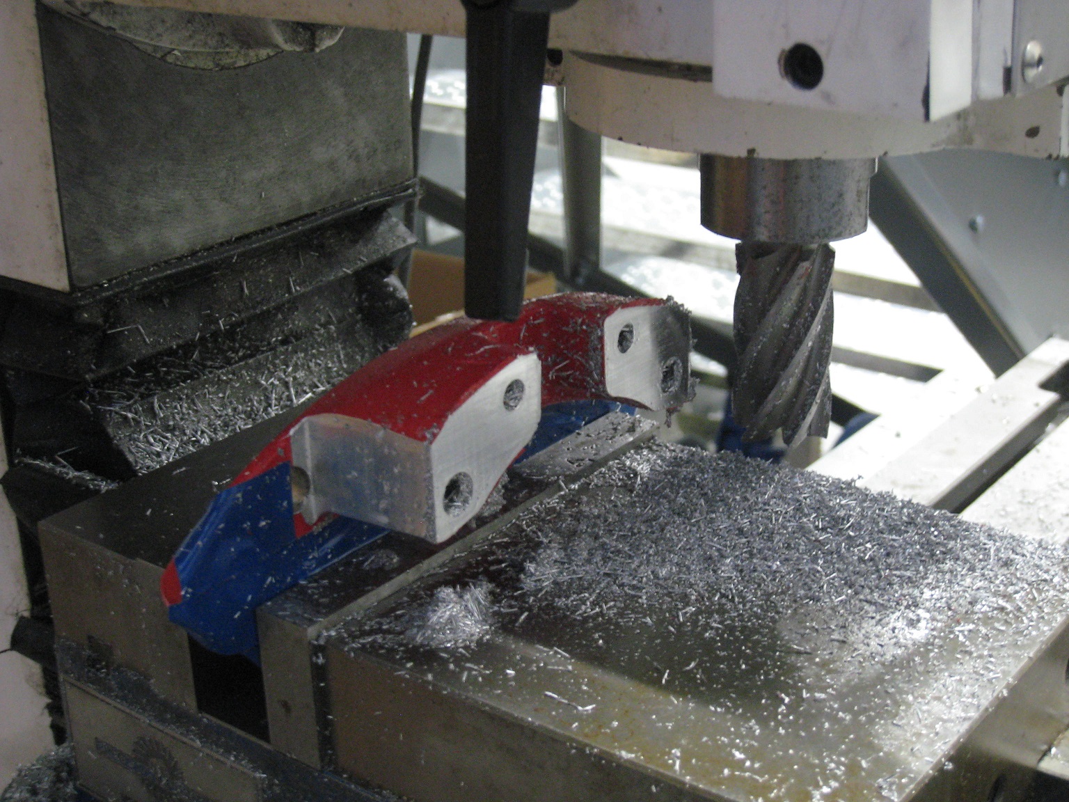
To gain banjo bolt clearance, I decided to narrow the caliper by removing 2.5 mm of material from the outer half:
For more banjo bolt clearance, I also removed 3.5 mm of material from the banjo bolt boss:
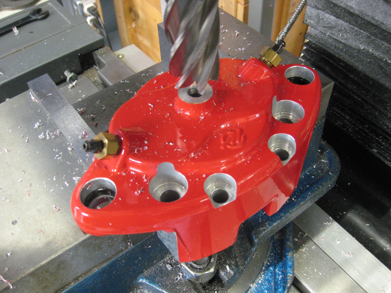
I plunged the cutter in the Z-axis, so any machining marks would be circular around the banjo bolt, to avoid creating any radial leak paths.
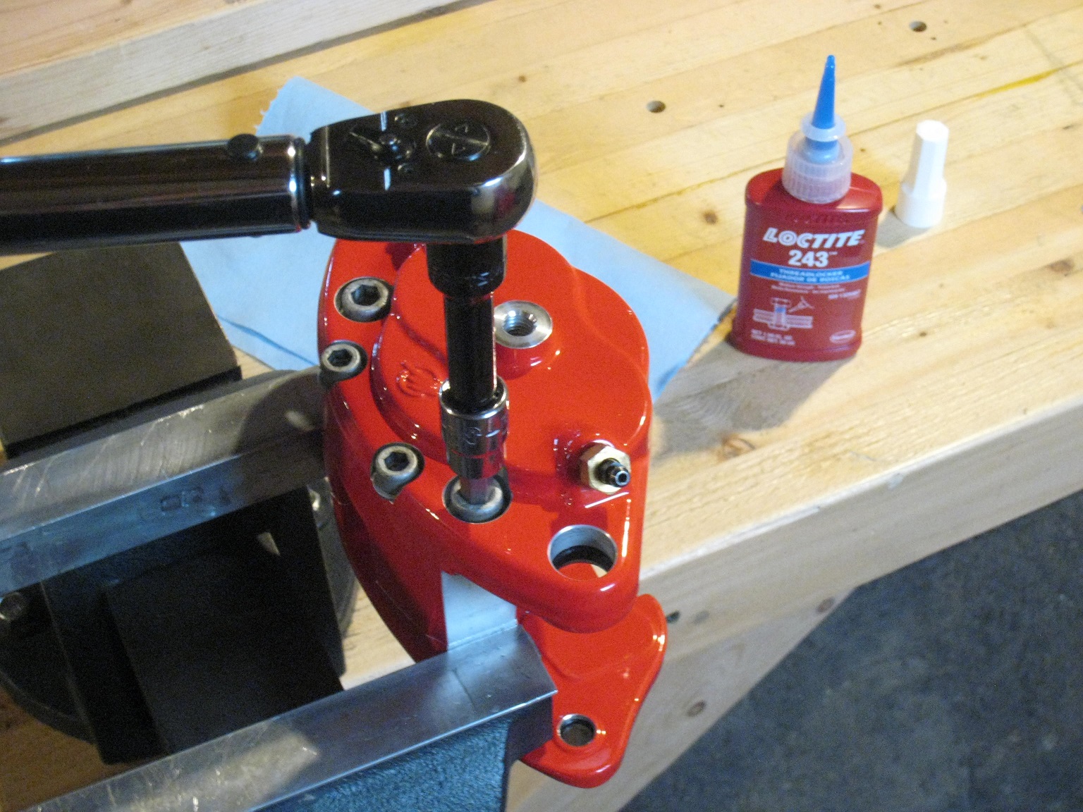
Then, I bolted the calipers back together:
Next weekend I'll be able to bring the calipers to the car and see how much the banjo bolt clearance situation has been improved.
Since it looks like I'm going to be replacing my sluppy123 hubs with custom hubs, if I need to gain more banjo bolt clearance, I may also draw my custom hubs with some positive offset to push the wheel/caliper a bit more outboard.
|
|
|
|
pmbrunelle
|
OCT 29, 05:28 PM
|
|
With the following mods, I finally have 4 mm of clearance between the banjo bolt and LCA:
2.5 mm removed from outer half of caliper.
3.5 mm removed from fluid port boss on caliper.
Banjo bolt head reduced in height.
Material ground off from LCA.
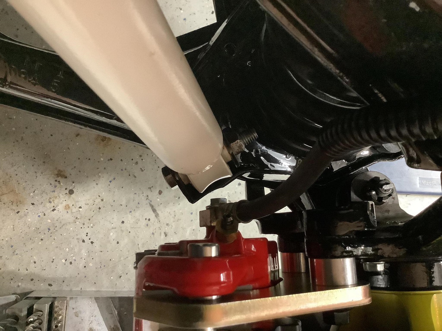
That's all with a stock sluppy123 hub.
I think that 4 mm clearance is OK, but if I end up making custom hubs, I'll add a bit more positive offset.
|
|
|
|
pmbrunelle
|
MAR 02, 08:11 PM
|
|
For my front hubs, I'm going with modified front rotor/hubs.
To set up the stock rotor on the lathe, I used a (modified) steering knuckle as a fixture. The steering knuckle is centre-drilled at both ends from the factory.
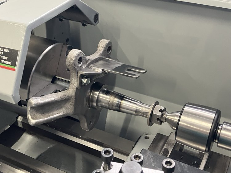
I crudely statically balanced the steering knuckle by balancing it on one of its centre holes. For torque transmission, I added a steel bracket, which drives one of the hub's ribs.
The setup worked fine without vibration at 150 RPM.
|
|
|
|
La fiera
|
MAR 02, 08:44 PM
|
|
|
Why are you taking material off the rotor? Is it because it doesn't clear the caliper?
|
|
|
|
pmbrunelle
|
MAR 02, 08:55 PM
|
|
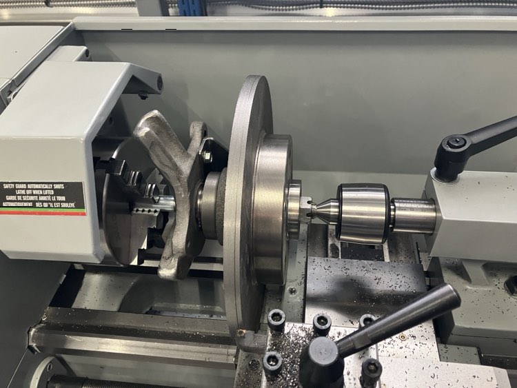
This is to convert the stock integrated rotor/hub into a hub which can accept a different (LeBaron) rotor.
I took off all the braking surface! I took the photo in the beginning of the job.
|
|
|
|
La fiera
|
MAR 03, 09:16 PM
|
|
|
|
|
Will
|
MAR 04, 06:55 AM
|
|
| quote | Originally posted by pmbrunelle:
This is to convert the stock integrated rotor/hub into a hub which can accept a different (LeBaron) rotor.
I took off all the braking surface! I took the photo in the beginning of the job. |
|
You located it on the bearing races to minimize runout in the final part? Are you planning to face the wheel mounting surface?
Looks like a lot of extra work vs. chucking on the inboard journal, if all you're doing is parting off the rotor
Or are you turning the rotor down from its original OD?[This message has been edited by Will (edited 03-04-2024).]
|
|
|
|
pmbrunelle
|
MAR 04, 08:38 AM
|
|
| quote | Originally posted by Will:
You located it on the bearing races to minimize runout in the final part? Are you planning to face the wheel mounting surface?
Looks like a lot of extra work vs. chucking on the inboard journal, if all you're doing is parting off the rotor
Or are you turning the rotor down from its original OD?
|
|
The LeBaron rotor centrebore is slightly large for the Fiero hub's wheel/brake register, so my plan is to build up the area with a Permatex Steel Weld (a steel-loaded epoxy), and then turn it down to fit the LeBaron rotor. This operation needs to be low-runout, so that's why I prepared the setup with location via the bearings. If the brake rotor is mounted eccentrically, then that will cause a static mass imbalance.
Yes, I will be skimming the wheel/brake mounting surface. Initially, that was not part of the plan, but the yahoos at Dynamic Friction (or at the Chinese factory where the rotors were produced) installed the lug studs with an excessive amount of interference (approx 0.025"). This caused some material to be displaced, proud of the surface, hence needing to take a skim cut to make things flat.
As the lug holes are undersized, I'll be able to ream them to 12.5 mm and install Dorman 610-323 studs.
In my previous post, I simply converted the braking surface into a pile of chips. That operation didn't need much precision, but I wanted to do a "shakedown run" of my knuckle / bearing-locating setup, before using it for the more fussy higher-precision operations.
|
|
|
|
Will
|
MAR 04, 09:40 AM
|
|
| quote | Originally posted by pmbrunelle:
The LeBaron rotor centrebore is slightly large for the Fiero hub's wheel/brake register, so my plan is to build up the area with a Permatex Steel Weld (a steel-loaded epoxy), and then turn it down to fit the LeBaron rotor. This operation needs to be low-runout, so that's why I prepared the setup with location via the bearings. If the brake rotor is mounted eccentrically, then that will cause a static mass imbalance.
|
|
The front LeBaron rotor has a smaller rotor pilot than the rear rotor. It's also slightly smaller outside diameter, but it fits the Fiero rotor pilot without modification, IIRC.
|
|
|
|
Will
|
MAR 04, 09:41 AM
|
|
| quote | Originally posted by pmbrunelle:
In my previous post, I simply converted the braking surface into a pile of chips. That operation didn't need much precision, but I wanted to do a "shakedown run" of my knuckle / bearing-locating setup, before using it for the more fussy higher-precision operations. |
|
I guess if you only need to make two, that's a fine way to do it... a part-off tool would be MUCH easier.
|
|
|
|