
 
     |
| Bringing a 88 Fiero Back to Life with a LFX Swap (Page 13/15) |

|
rglasco101
|
NOV 08, 10:15 AM
|
|
|
Did you have to modify the gear shifter shaft to fit the impala knob?
|
|
|
|
MikesFirstFiero
|
JAN 24, 07:10 PM
|
|
Wow! Has it been that long since I did anything to this post? I got a job at the local O'Reilly's store and that (and the car and honey-dos and ...) seemed to suck up lots of time. Now I've got more time since winter is here and I'm not working on the car, just driving it, even in the snow. Couple of weeks ago it hit -15F here for a few nights. But it did start and run without any issues.
I'll pick up the story from where I left it off.
To answer the last question about the shifter I wanted to lower the length so it didn't stick up so far. I chopped off an inch or two and shaped the top to look similar to the Impala lever. I have not fastened the knob to the linkage permanently since I'm not done taking the console apart. To lock it in place I need only cut a notch on the shifter tube for the knob to latch into. I'm thinking about making the remote entry and remote start work next year. The shifter lock release is on the front of the knob, to make that work I made up a new actuator rod from a fiberglass rod laying around, just needed the right length. Until I lock the knob in place I need to push down on the knob when I pull the trigger or it pops up and doesn't always work. Since I did want the manual transmission mode to work I needed to keep the Impala knob since it has a shift awitch and wires to the harness.
I decided to replace the side markers with LED lamps and discovered this isn't as simple as I expected. The rear lamps are not a big problem but the lamp strips are rated at 12V and will burn out if the current gets too high. Modern engines usually output between 13.8 and 14.2V which will make the LEDs too bright and kill them quickly. I added a series resistor of about 47 ohms 3W and that lowered the current and voltage to give me the brightness I wanted. Note the rear wiring is polarized, hooks up only one way. However the lamps will dim significantly once the engine is stopped since the resistor isn't needed with the battery voltage dropping to about 12.5V resting. I bought my LEDs from VETCO.NET in Yellow & Red, about $5-$10 per strip. They have bridge rectifiers, resistors & zeners too. Cut the end of the back of the fixture and slipped it in. Used heat shrink-tubing for all wiring and then potted with silicone RTV.
The fronts proved to be more difficult since the original design has current flowing in both directions depending on the parking lights being on. When the parking lights are off the currrent flows normally and all is well, the side marker works in unison with the turn signal lamp. But turn on the parking lamps and the side markers are now on normally. Using the turn signal requires the side marker to be OFF when the Turn Signal lamp is ON. The wiring uses a different circuit that runs current in the opposite direction. LEDs don't like that. One solution is to add a relay to each turn signal lamp and wire that up. But that's a mess.
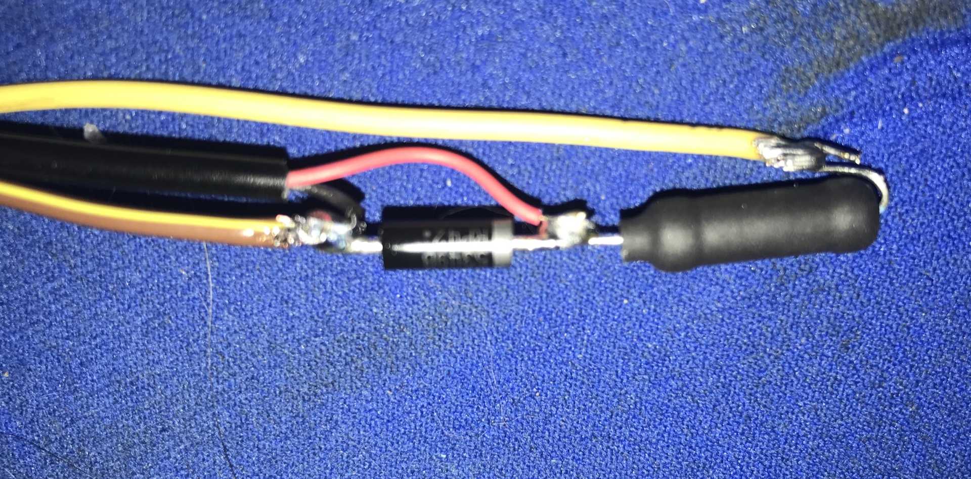
So I added a small SMT 2Amp rectifier bridge to each side marker strip. The AC inputs to the bridge come from the car's wiring harness and the DC output goes to the LED strip. The diodes make the power is always has the correct polarity, but they cause another problem. The bridge now causes the 14V power (with engine running) to be about 12.8V after the bridge (diode drop x 2 is about 1.3 to 1.5V) Rather than use only a resistor I decided to use a 12V Zener diode as a simple voltage regulator. Zeners are different in that they are hooked up backwards (Anode to common) and will not conduct until the voltage is above the zener rating. Once that voltage is reached the diode conducts (in the opposite direction). So you need a resistor before the diode to limit the current. But that will be lower resistance, about 24-33 ohms in my case. And no relays to fail or mount. The wiring from the car harness is not polarized so hook up either way to the bridge rectifier. But do not ground the output negative going to the LED lamp strip.
Front wiring from Bridge to LED strip.
Black & Red go to strip, Black is negative
Yellow goes to Bridge (+)
Orange-Yellow goes to Bridge (-)
Schematic of Front Wiring
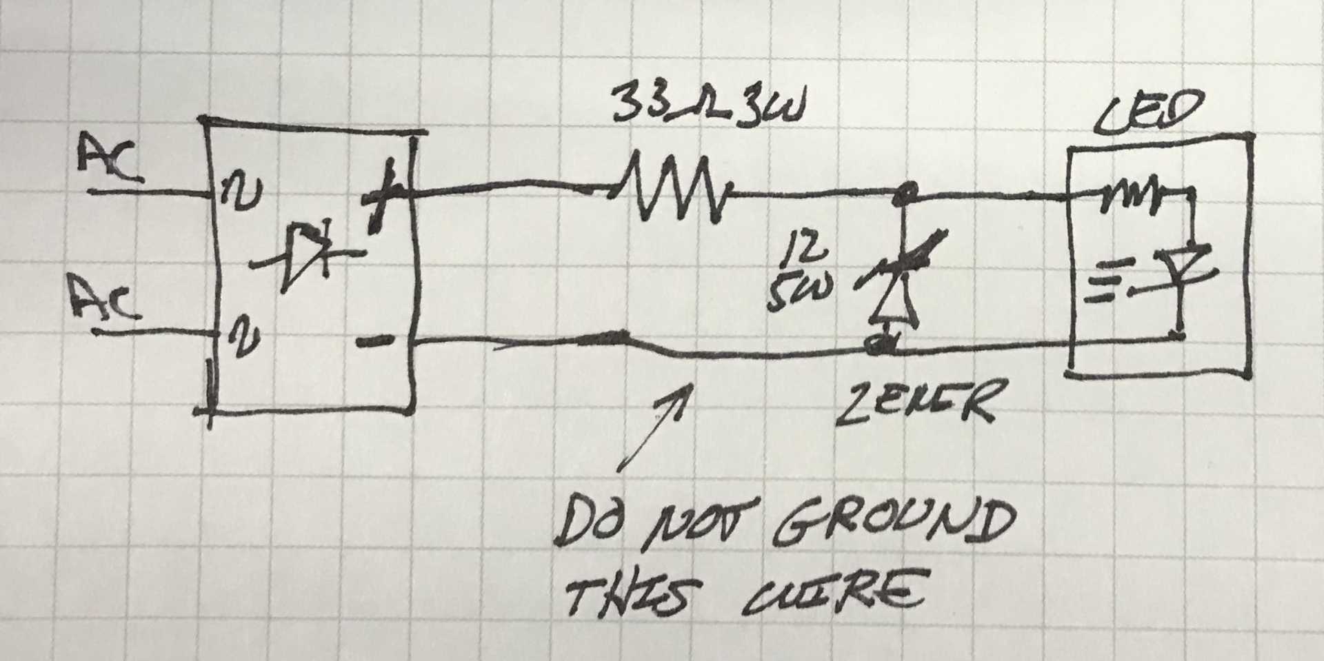
The front turn signal lamps continue to complete the side marker circuitas in the original design.
I might not work right if these incandescent lamps were replaced with LEDs but I haven't tried LEDs in the front turn signal lamps yet to check this out.
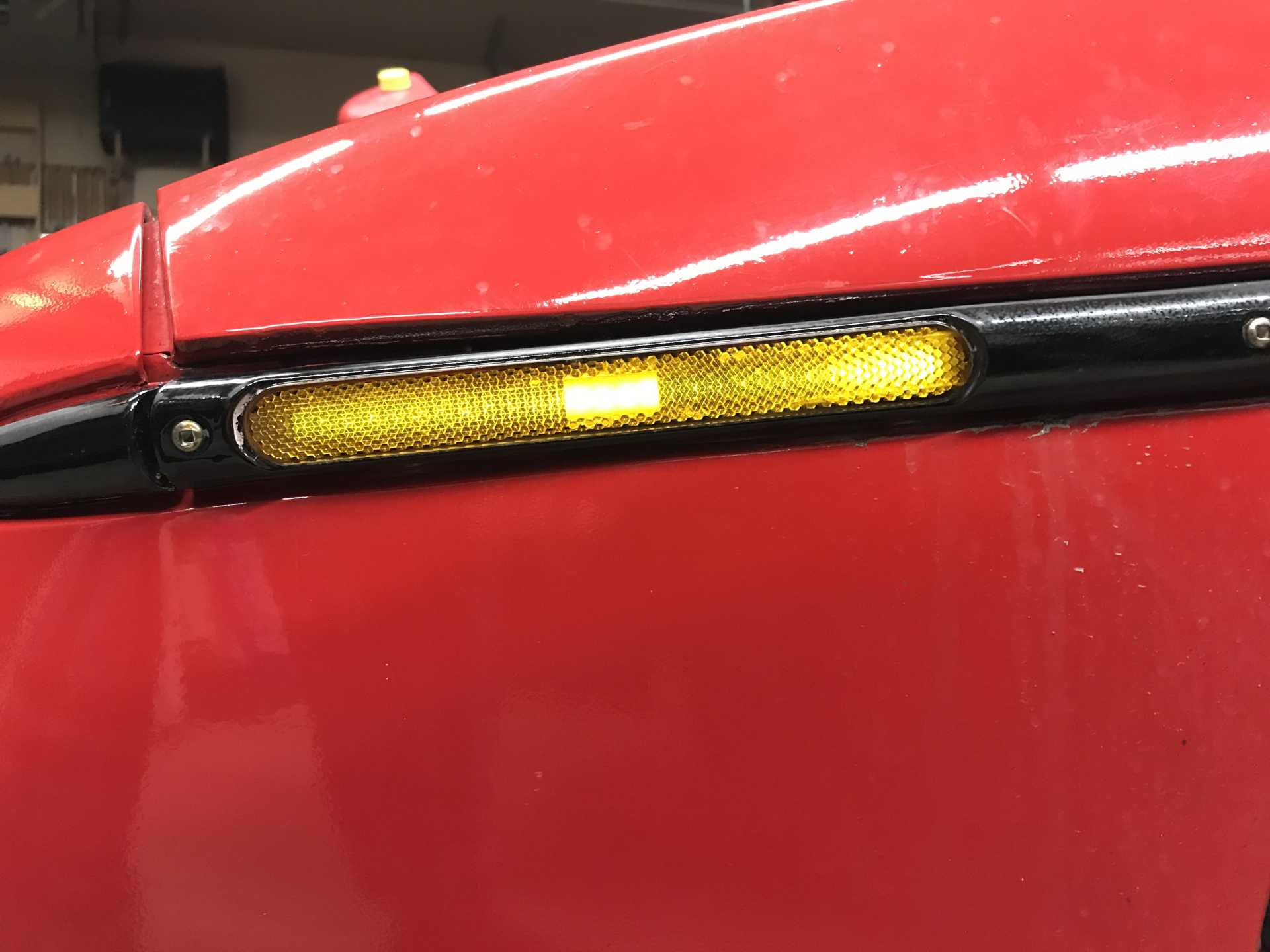
Front LEDs look washed out from this view. Reflectors in the fixture cause this, also car is not running.
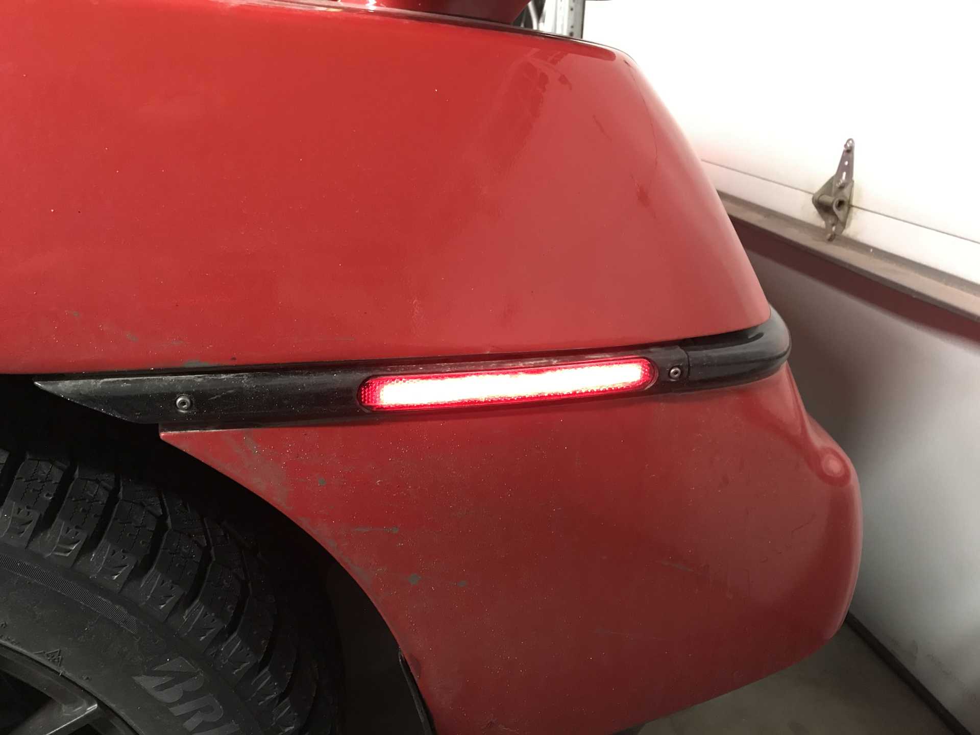
Rear LEDs look better Might need to lower the resistance more. The Zener only clamps the brightness to keep the LEDS from burning out.
Next it was time to do a better job of front end alignment and to align the rear for the first time (probably in 25 years!)
I made an alignment jig that mounted to four jack stands, held on by C clamps. These were used bed frames cut to length with notches for the strings. The width was set to match the wheel fixture centerlines to simplify the mesurements. I had some 4 pound monofilament to run as the "string", the thinner the better.
Front and rear jigs in place
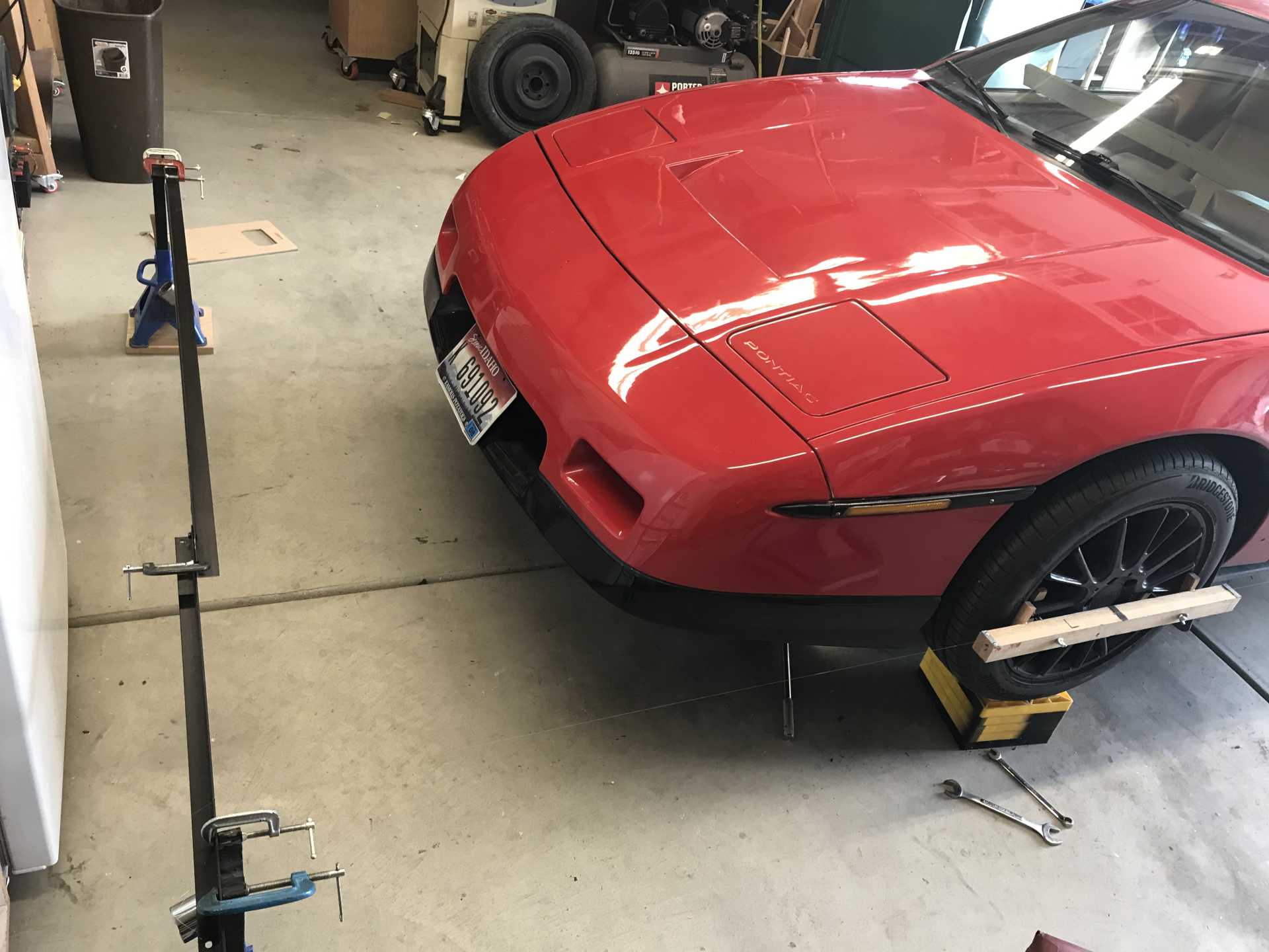
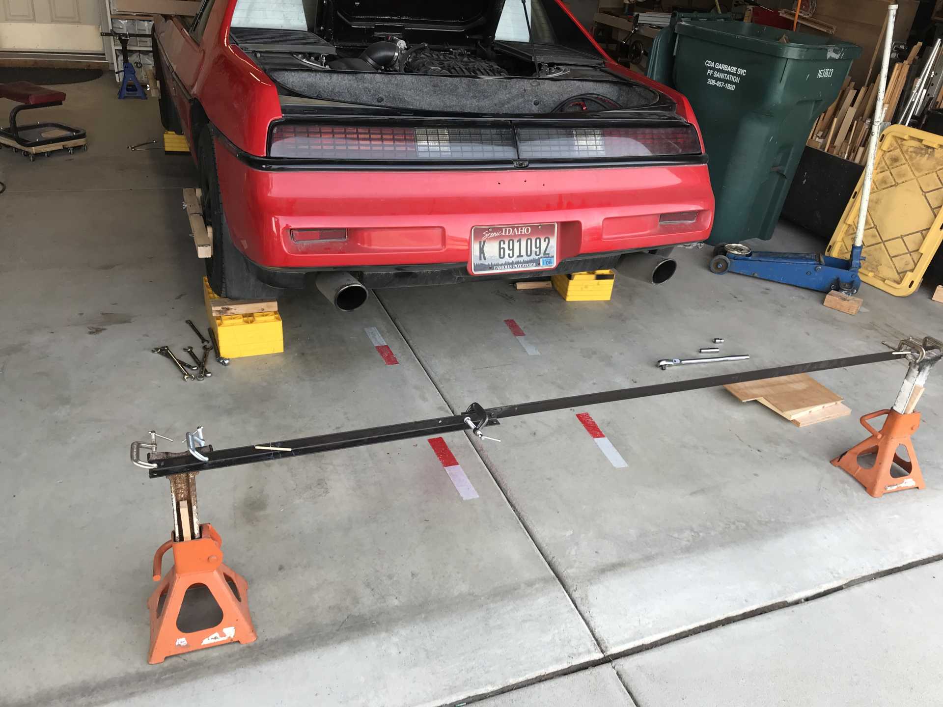
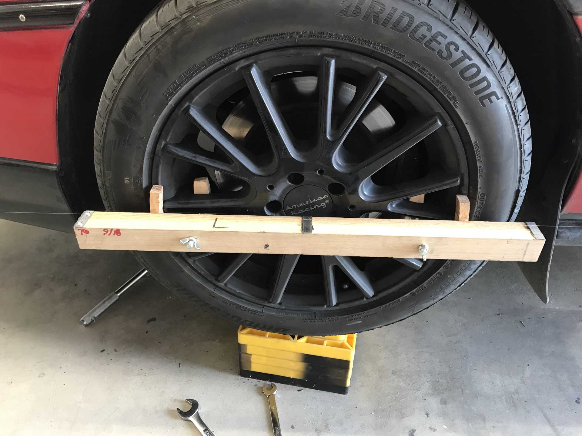
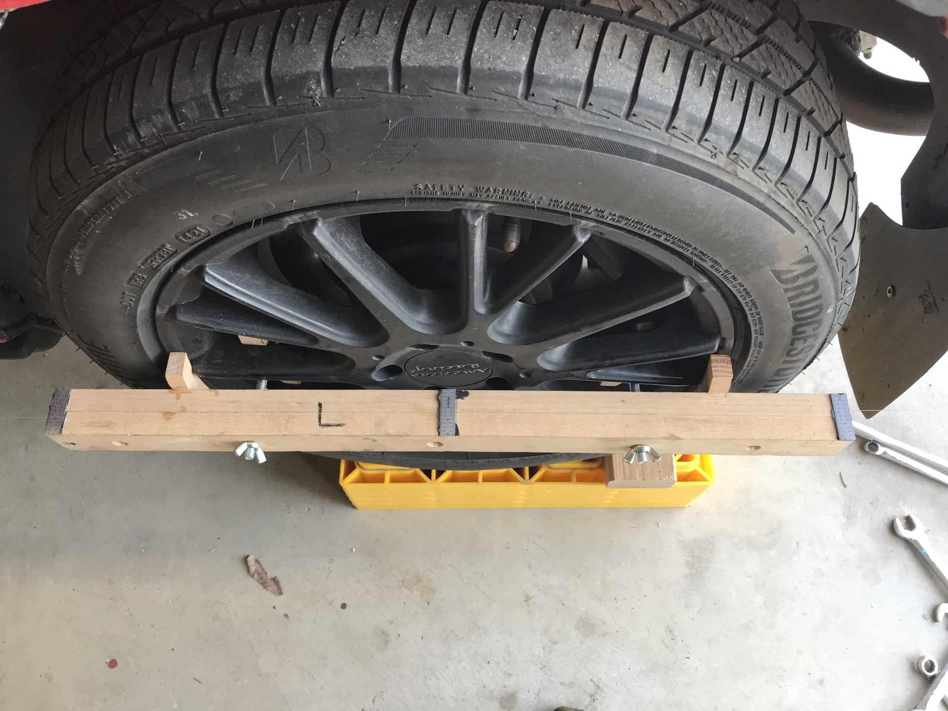
For each wheel I built a measuring fixture that bolted to the wheel. I used cut-up 6" scales for measuring at the center and ends of each wheel fixture.
The first thing I discovered was the rear toe-in was almost 1/2 inch on each side. No wonder it ate tires for breakfast and didn't want to go in a straight line at highway speeds.
The rear toe adjusters needed to come off to be unfrozen. It took an hour each to get them apart and cleaned. Plus an hour to disassemble and reassemble after.
You needs good chemicals to work on these ancient adjusters.
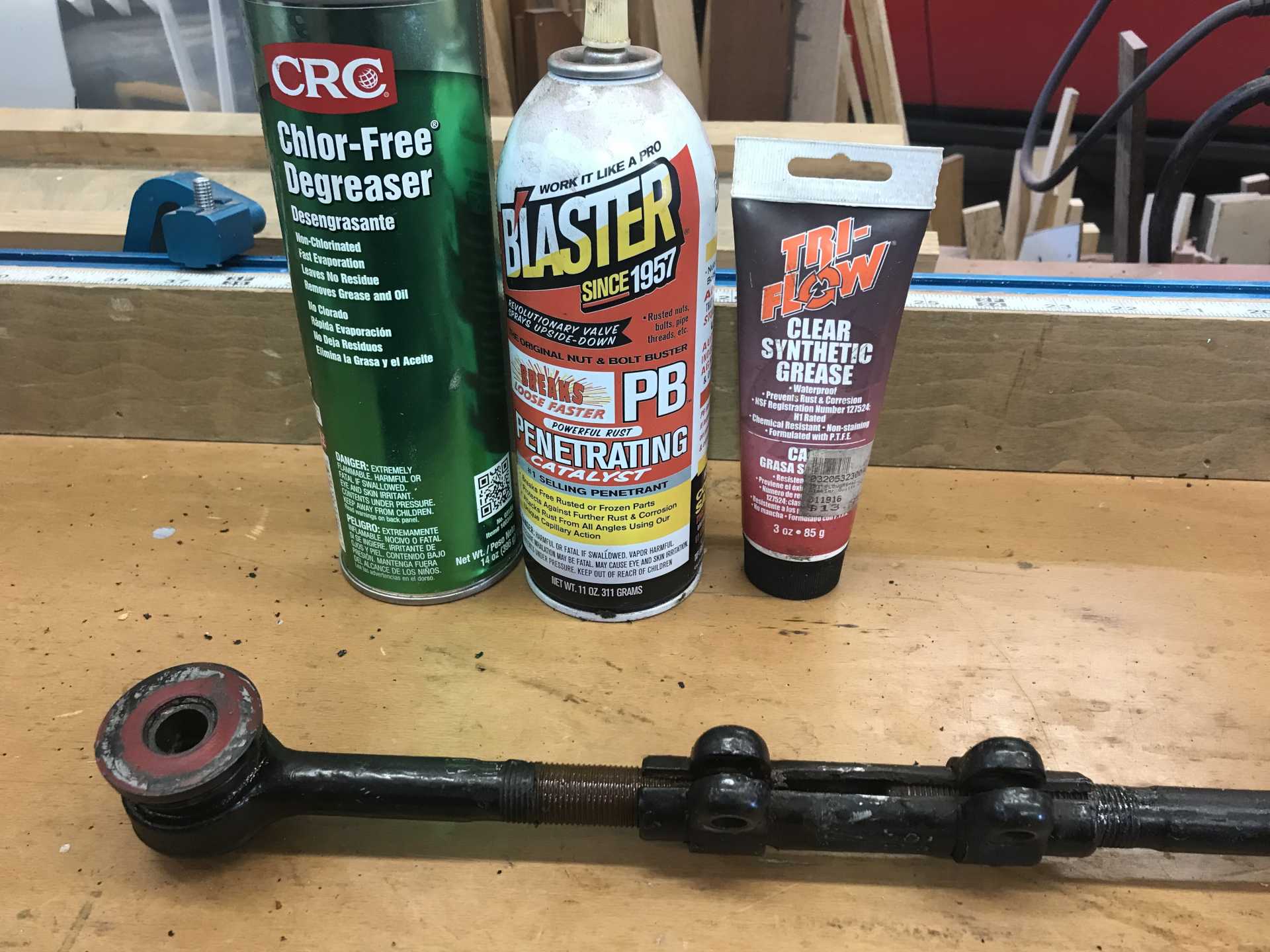
When adjusted it is much better with a slight right pull. It also doesn't want to be skittish in the rear any more. I'll address that pull later and give the front a bit more toe-in since there were more pressing issues to deal with.
Getting ready for the NorthWest Fiero Fest and... the right side CV joints fail. Crap.[This message has been edited by MikesFirstFiero (edited 02-20-2025).]
|
|
|
|
MikesFirstFiero
|
JAN 25, 04:58 PM
|
|
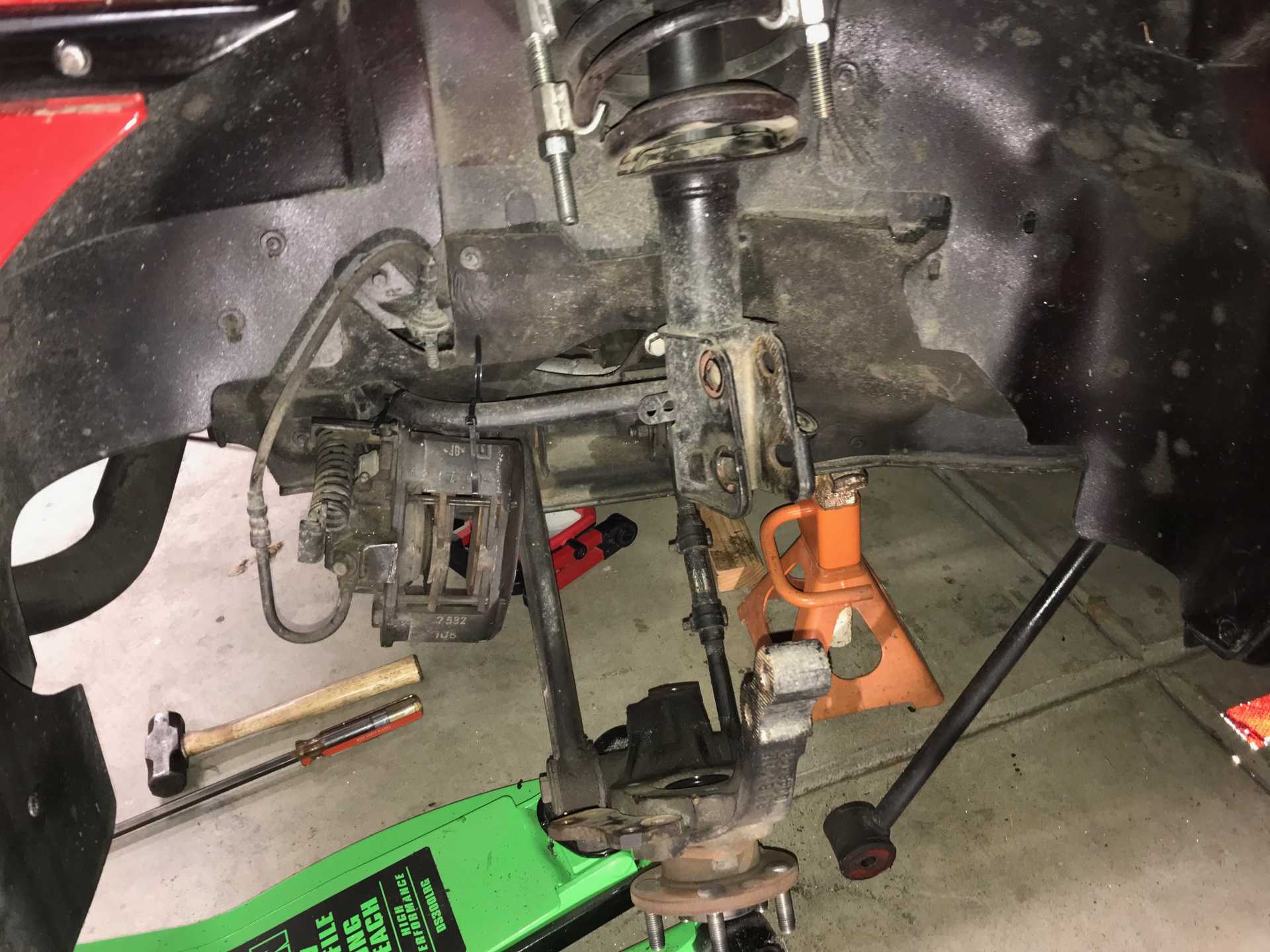
The RR CV axle began to make noises so it's time to replace the joint(s). To do this I buy an Impala axle, if the inner joint is bad, or try to find a real Fiero CV outer joint, otherwise buy a Fiero axle. The problem is the non-OEM Fiero axles are not always able to be disassembled. The ones O'Reilly sells fall into that type. The outer joint is not intended to be removed. It has no accessible C-ring to release the joint. Luckily there are still some original CV joints (sometimes) available. If there is another outer that would work I'd like to get a few. Eventually I did find a for-real outer joint a few months ago and ripped the two-year old axle out.
I've been here before. Now have a new Harbor Freight Daytona Low Profile Long Reach jack that is much better for getting under the car. The front is lowered and this makes it much simpler to lift.
Failure was by water contamination. The boot openings for the axle just did not seal properly with the expected results. The inner had completely failed while the outer might have been salvagable but I replaced both. The inner is totally gone
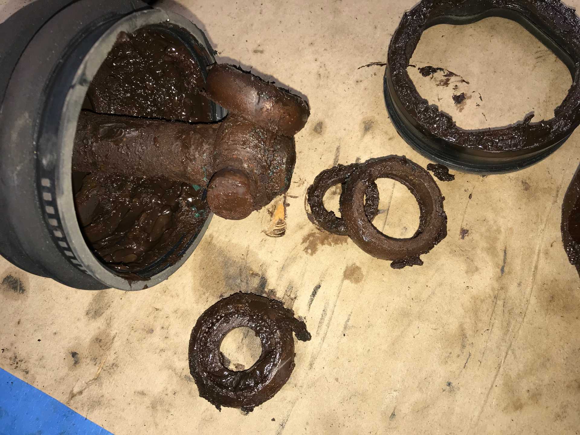
And the outer is not happy either
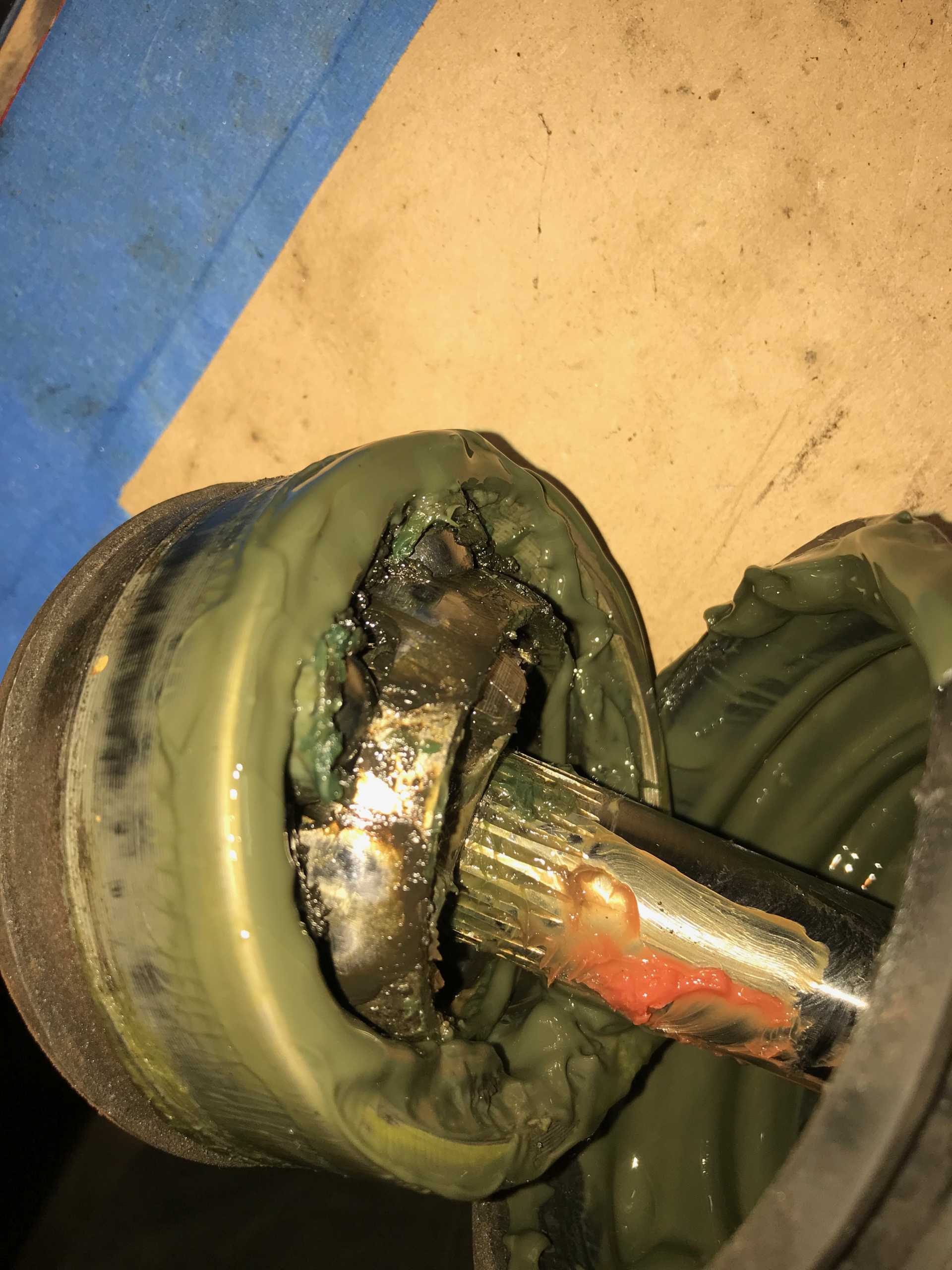
Another concern is the axle splining fits too loosely to the tripod hub. This causes a noticable Klunk sound and the impact will eventually damage both of these parts. Then I found a product that can fix this called Locktite 660. It is intended to solve this exact problem. It's expensive at $60 for a 4oz tube but what the heck. It is a paste that hardens over 24 hours is a permanent fix and can be removed by heating to 500F. I cleaned the shaft and hub and applied enough (about 1/2 oz) to fill all the splines, assembled the pieces, snapped on the C-ring and let it set overnight. Next day it was setup solidly. (Writing this now after 9 months it has been dead quiet).
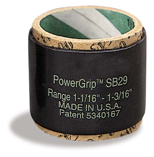
The boot leakage problem has concerned me so from the start. The clamps simply don't fit well enough to the axle end to properly seal. The seal on the CV end however being a bigger diameter has not proved to ba a problem. I dug around and found that Gates makes a Heat-Shrink hose clamp in different sizes with a grip range of about 1/8". These are substantial and are shown being used on truck radiators. At about $5 each they aren't cheap but the problem needs a better solution. Being a polymer ring in tension they should be able to seal if the rubber/plastic boot shrinks in the winter and to provide constant pressure since there is no overlap joint of a metal clamp.
Gates SB Clamp
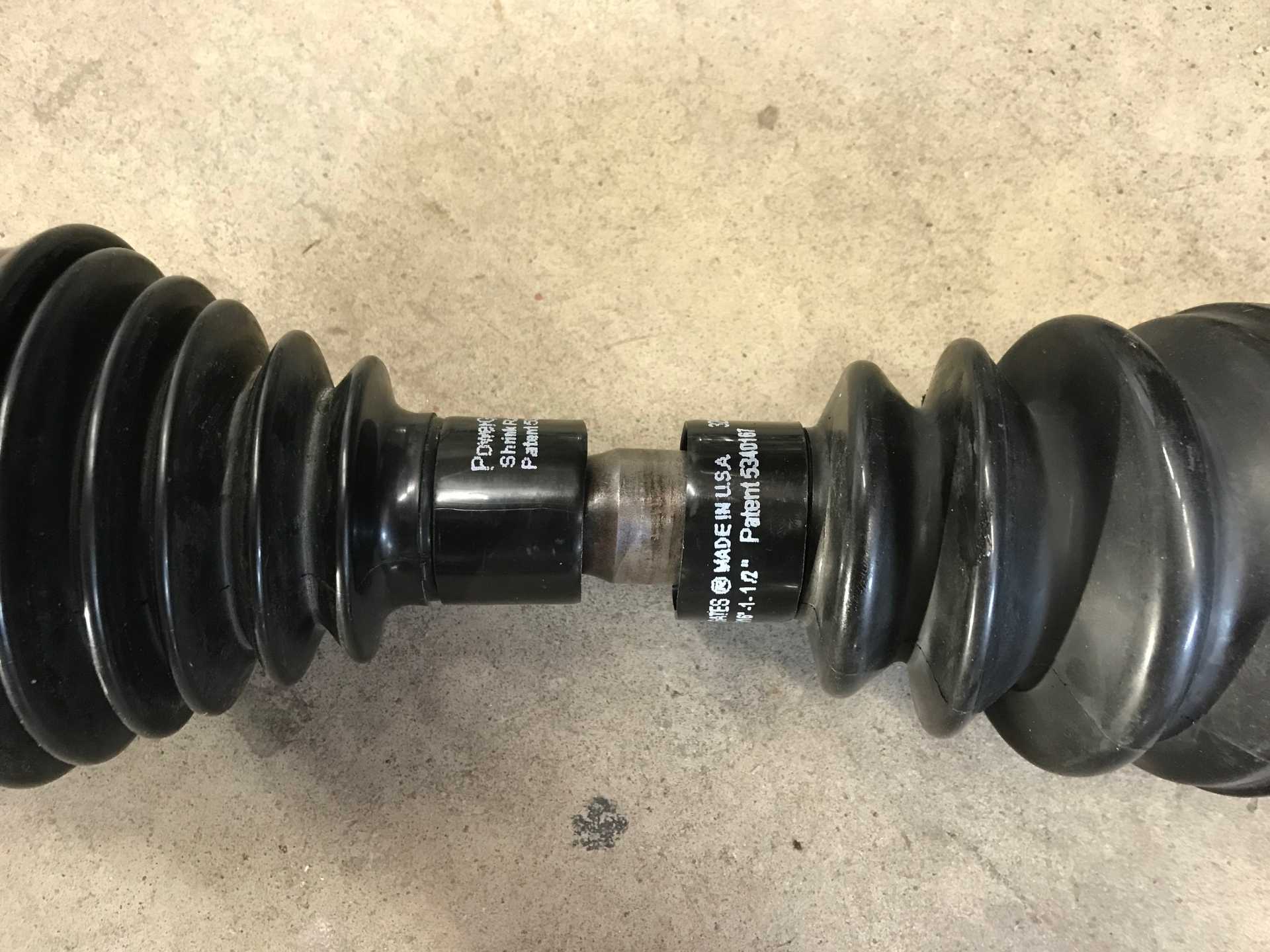
I bought a few and popped them on the shaft & boot before final assembly
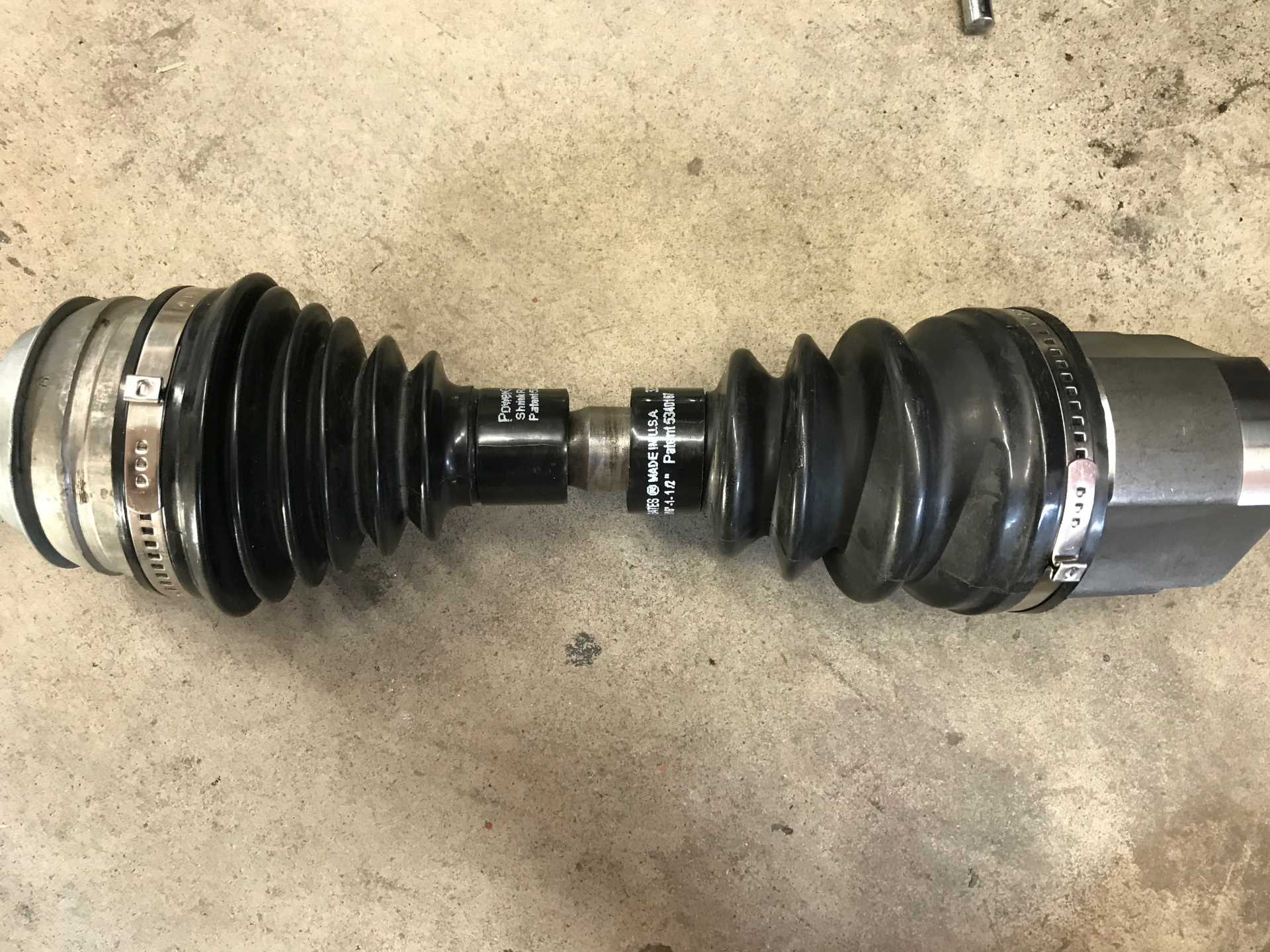
A Closer Look Before Shrinking. They are almost a tight fit over the boots
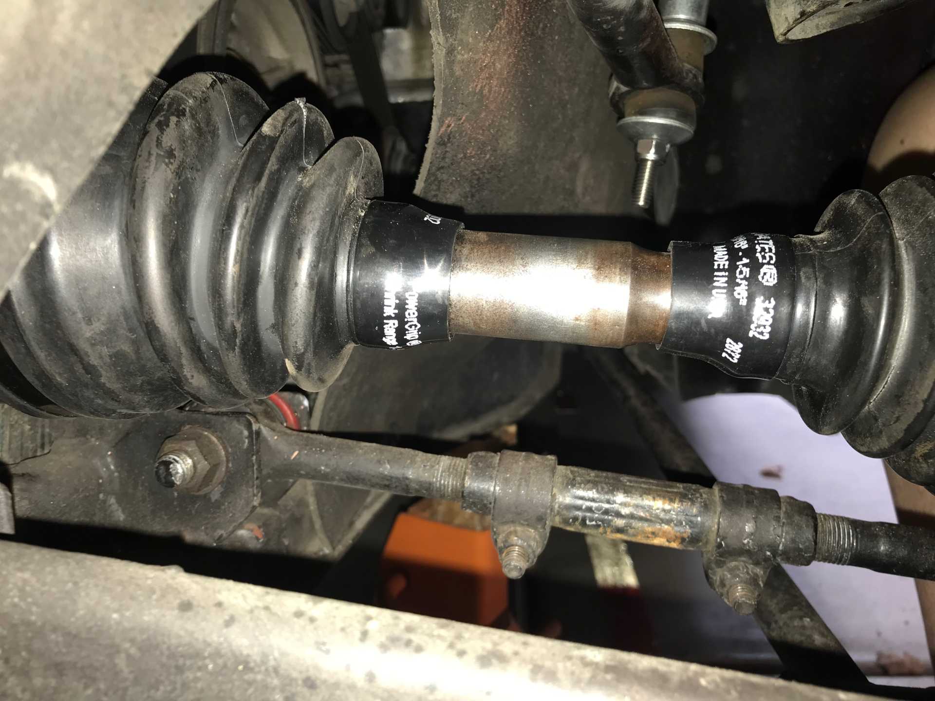
Then I got out the heat gun and shrunk them
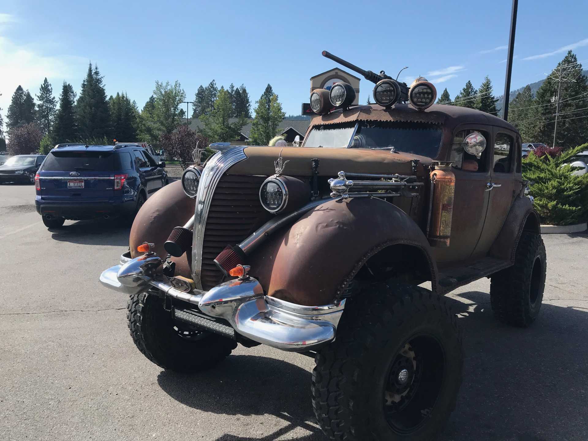
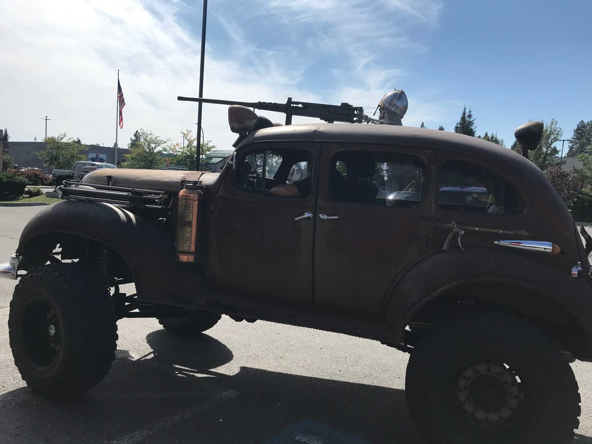
Sometims you see some unusual cars on the road. This showed up at the store the other day.
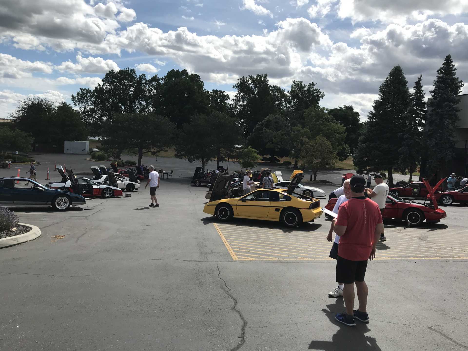
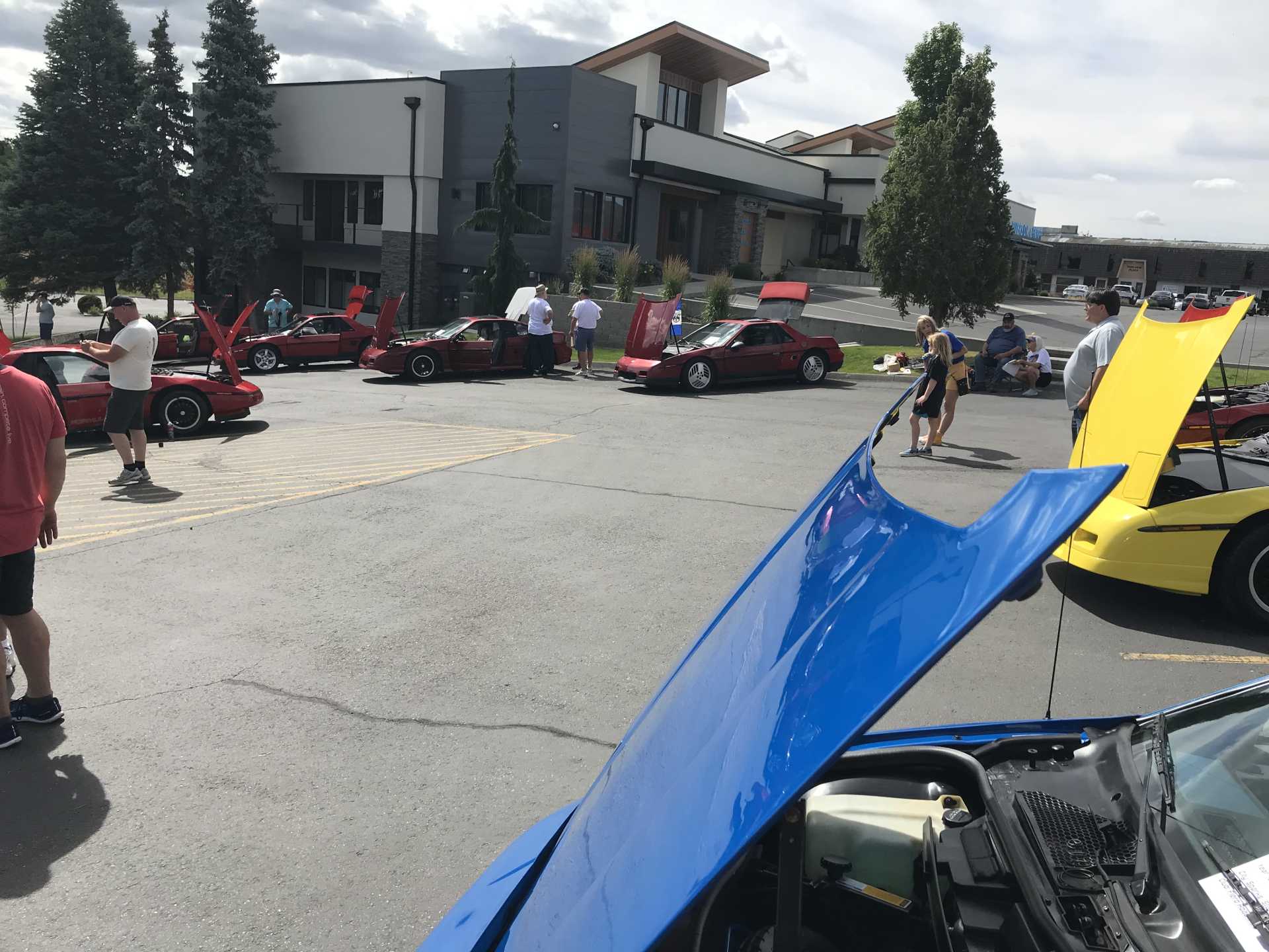
After putting everything back together It was time to head down to the Tri-Cities in Southeastern Washington for the NorthWest Fiero Fest. About 35 Fieros were displayed with a great variety of ideas of how to present a Fiero. Lots of engine swaps, interior and exterior modifications, paint schemes and lighting solutions were on display. A really fun gathering with endless talk about our favorite car.
A couple of photos of the cars on display.
And I Never expected this... I am truely honored to receive this award.

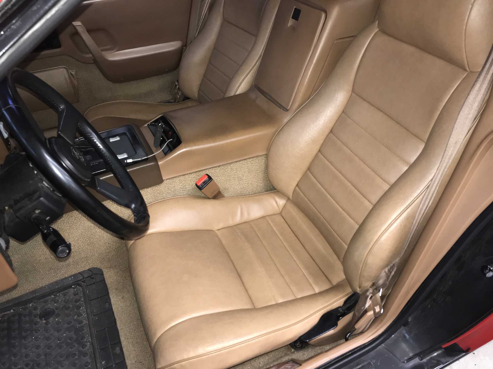
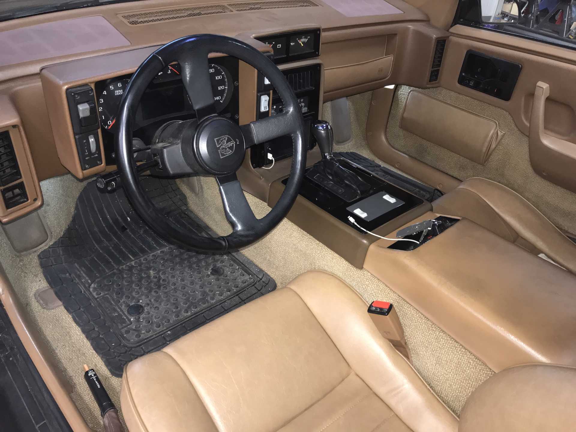
Going to the Fest did show up one glaring issue with my car; the original interior was beyond help. And then the fabric began to wear out so it was time to contact Mr.Mike's for a set of new covers. Calling them covers is actually undervaluing what he provides. His products are a complete upholstery product that provides everything you will need to have a professional-quality interior. The customization options are seemingly endless and the materials and workmanship are first class. My wife is a Tailor and was impressed by the details of how the covers were constructed. Mike provides a product not available anywhere else at a very reasonable price. Be sure to read everything Mike provides and follow his instructions to the letter. Plan on about 2-3 hours to do each seat, have a clean work space and wash your hands before starting. And be careful of sharp tools when workinglest you kick yourself or even worse the covers!
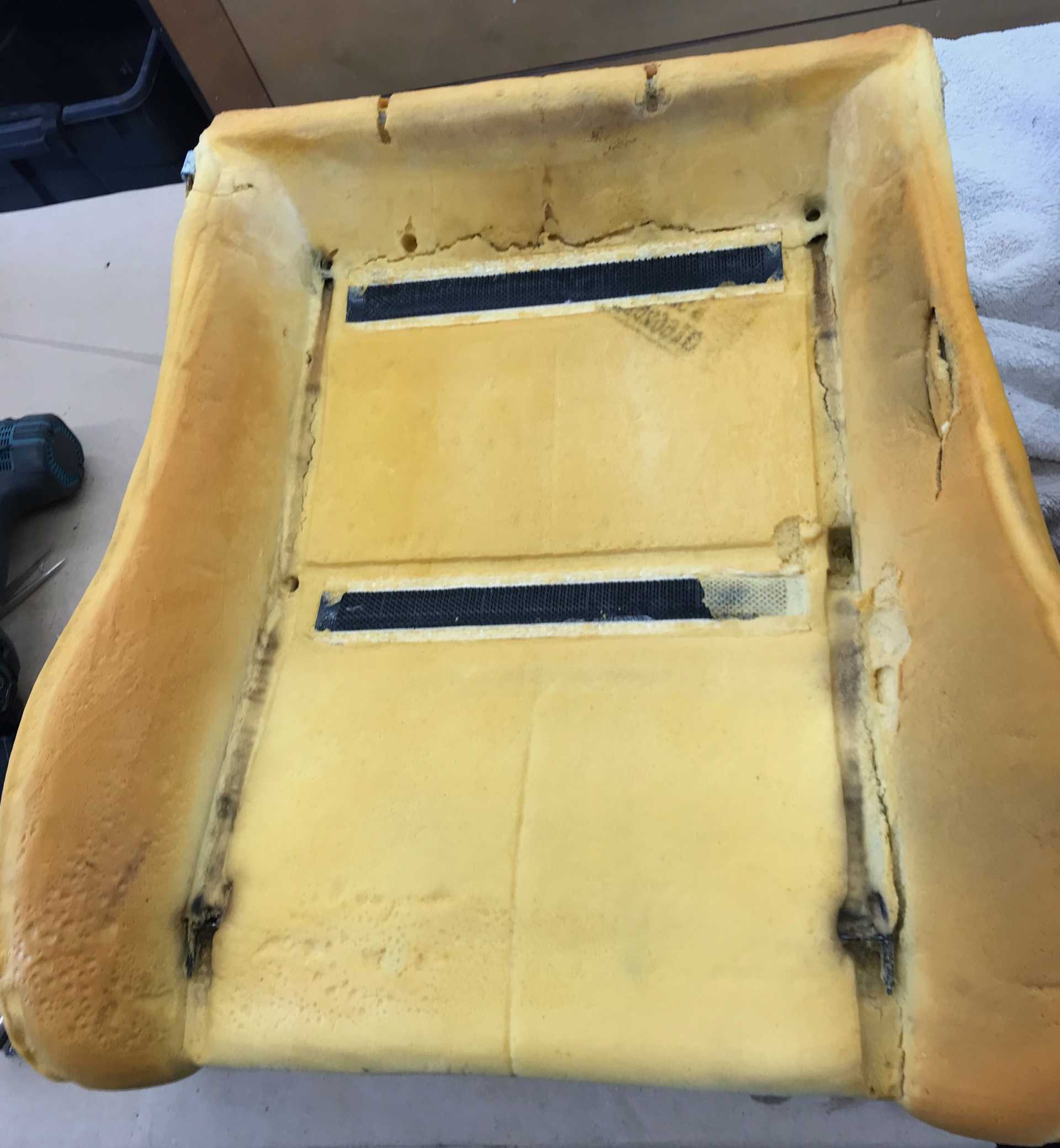
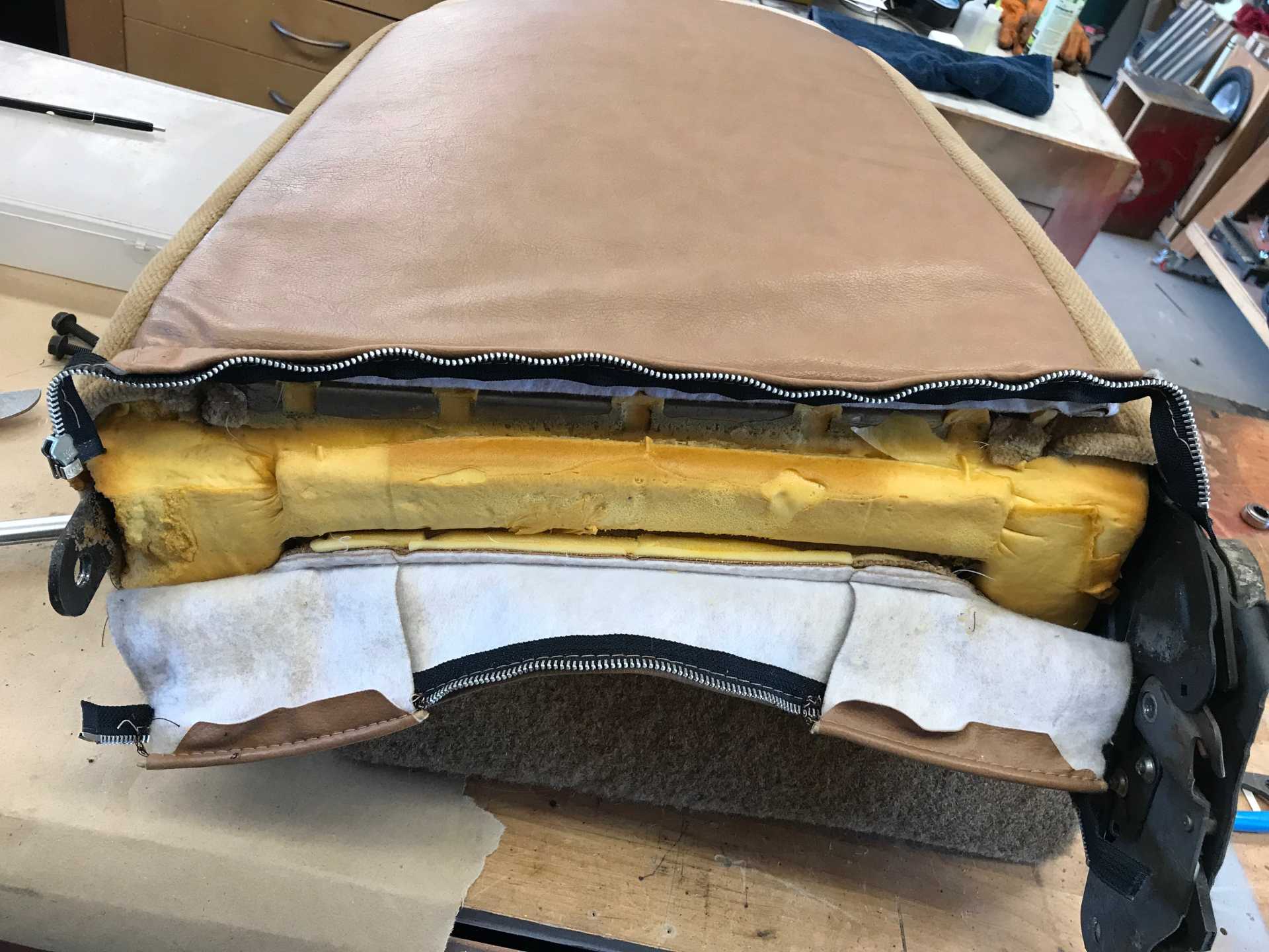
What the original seats looked like
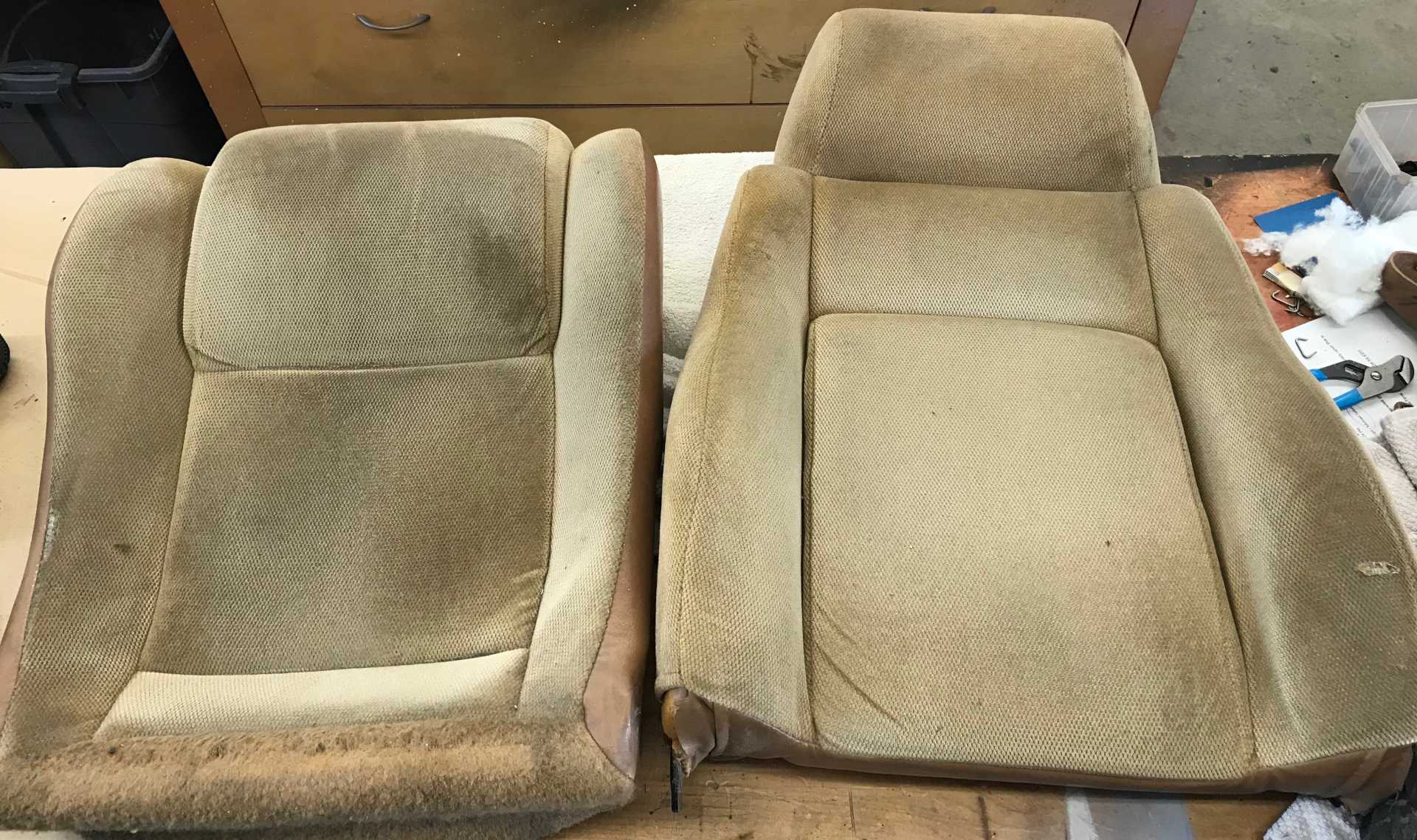
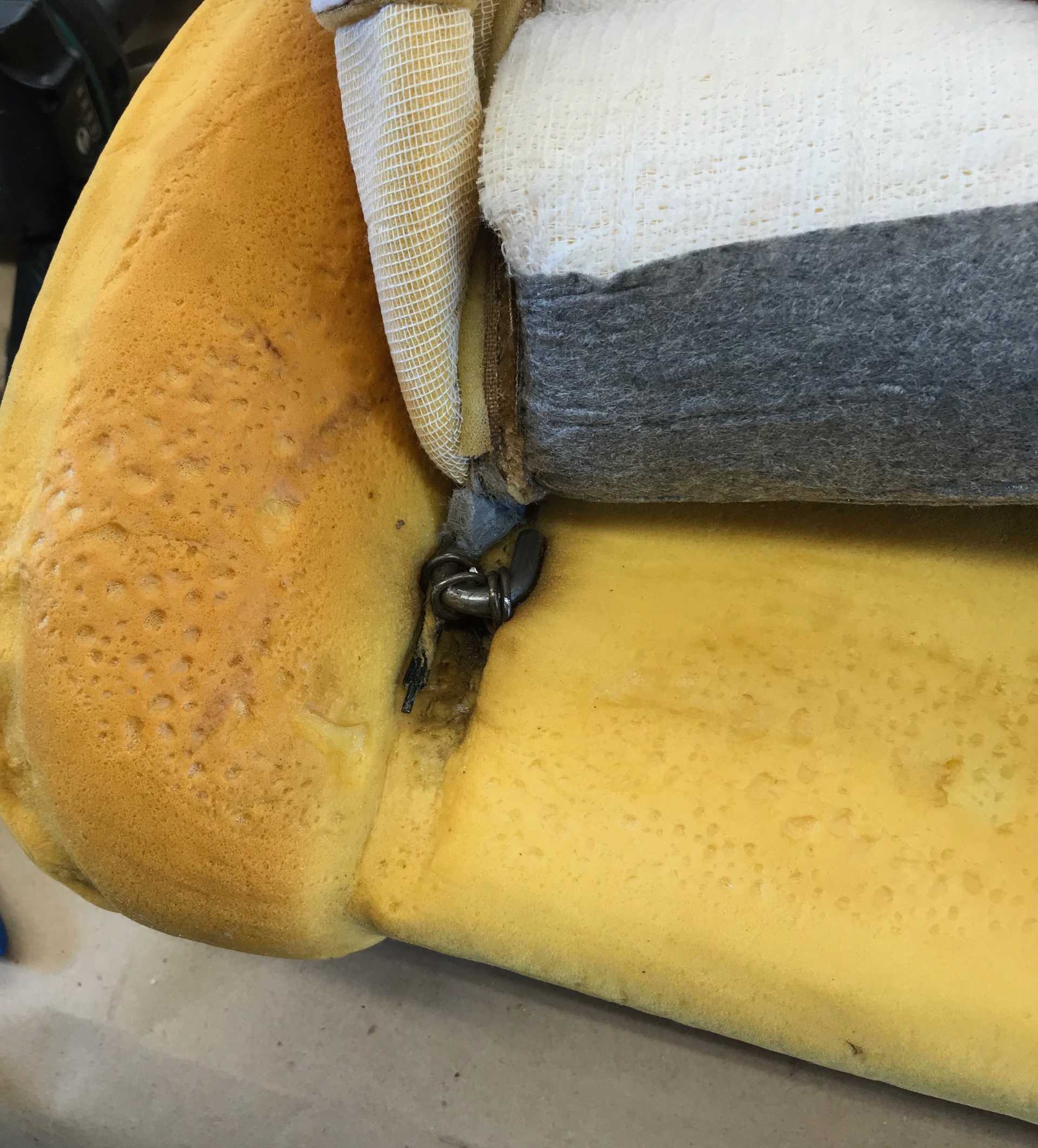
The driver's seat bottom. Note the cut foam where you exit the car. This is caused by the sharp pan edge below the foam. I added a length of 1/2" heater hose over this edge to reduce the pressure when you sit on it every time you exit the car. I also added some replacement foam and then installed the batting and cover.
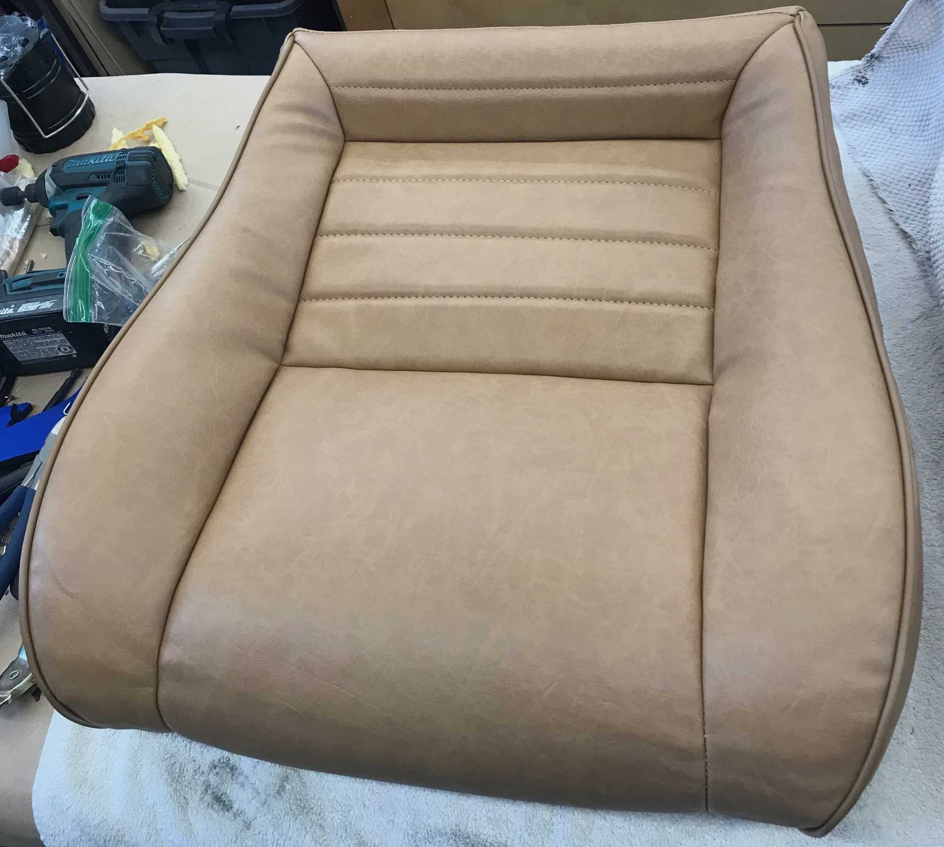
Next you add the new bottom cover and apply it over batting to remove wrinkles. Takes a fair amount of pulling, tugging, smoothing to get it neatly in place.
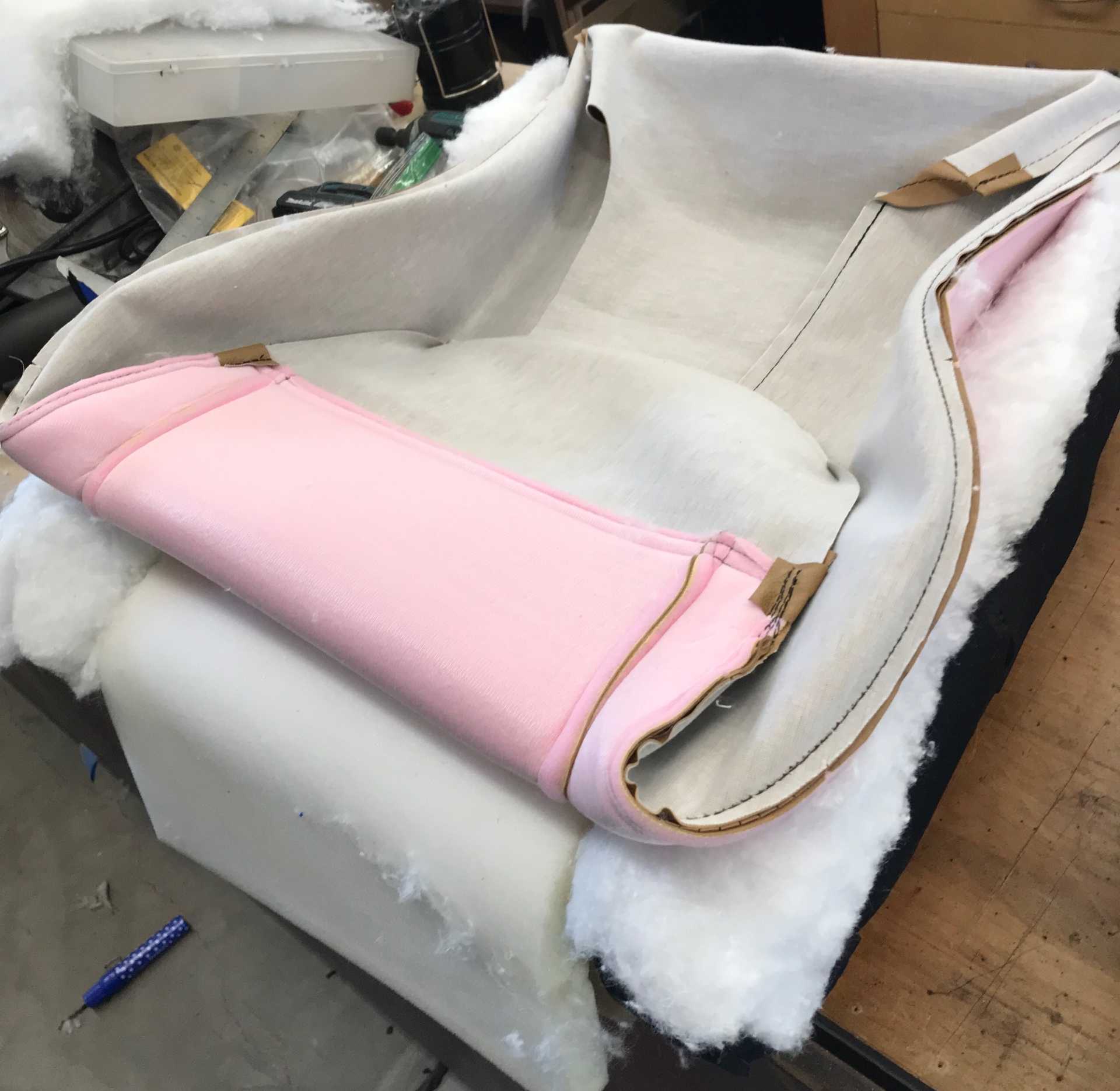
The edges of the inner seat cushion are ositioned by two of these steel rods that are held in place by hog rings. A very effective solution to give a professional look. They aren't easy to get in place but work on it and you will get it done. Be sure the rod ends are in the right place at the back, under the seat frame.
And this is the finished result. Those minor wrinkles will be gone in a day or so. Don't skimp on the batting, plan on using 100% of what is provided in the kit. You will also become adept at installing Hog Rings with the pliers Mike provides. Those hold the cover firmly in place.
The seat back slips on with some (lots of) pulling and tugging too. It also has retaining rods to be installed and has a zipper to close it at the bottom.
And the final result is Great! These photos were taken six months after installation and they look wonderful. I chose the Mercedes Vinyl material and really love the texture, color and feel. Could not be happier.
Now that it is getting hot it's time to look at making the A/C work.
|
|
|
|
fieroguru
|
JAN 25, 06:34 PM
|
|
|
Glad to see someone else doing a DIY string alignment! Also, love the idea of using the heat shrink tubes for CV boot clamps!
|
|
|
|
MikesFirstFiero
|
JAN 25, 11:28 PM
|
|
The string alignment method works quite well and I worry that today's mechanics have no clue about what it takes to set the front suspension up. Plus it's cheap to make and not difficult to do. The car is on blocks to make it easier to work on. Those Gates SB axle clamps are still where I put them too.
Time to try to make the Impala A/C work with the Fiero. The Fiero started life as an R-12 unit. The system was totally leaked out after sitting for more than 10 years. But with the Impala LFX there is no simple way to replace the compressor with the old 2.8L unit. Being 30+ years old it probably needed a complete overhaul. What about the Impala compressor? Can it be used? Well it is quite different, it uses R-134a in some cars and R-1234yf in others and it will take some pipe-bending to clear the cradle and alternator and oil filter.
R1234yf became manditory in 2021 with 134a being obsolete for newer cars. The chemical formula for 134a and 1234yf differ by one carbon atom. The structure of the molecule do differ somewhat. Since they are very similar in composition and characteristics the compressors for 1234yf and 134a are almost identical in pumping, pressure and heat ransfer characteristics. As for the refrigerants 134a costs $12/12 oz. can, 1234yf costs about $65 for the same amount. 1234yf is more reactive so it must be changed more often since it reacts with contaminants in the refrigerant oil. This is sounding more like a money-making planned obsolescence scheme with 1234yf costing 5 times more and needing replacement more often. As a result if you own a post 2020 car there are charging port converters on the market so you can swap (illegally) to 134a. Since R-12 was out of the question, I decided to upgrade and use R-134a.
The Impala compressor is a variable displacement design that has two electrical connections. One connection operates the compressor clutch and the second operates a displacement solenoid. The solenoid in the Impala uses Pulse Width Modulation (PWM) to adjust the valve position and the amount of cooling to deliver. Well I don't have any means of controlling that solenoid from the car's 1988 electronics. To do so would require the complete Impala HVAC controller and countless hours to make it work. Damn. So what I did was by trial and experiment determine that if a constant 6V is applied to the solenoid the valve will be opened enough to cool the car. Adding a branch wire from the clutch power feed thru a 10 ohm 5W resistor gives the solenoid the 6V (about) needed. So far it has worked once al the leaks were solved. I'm told other LFX compressors for 2018 (camaro?) are the older on/off control type, but I didn't want to buy one to find out is somehow incompatible with the FWD LFX configuration.
So much for the controls, refrigerant issues and design considerations. Time to get down to wrench turning.
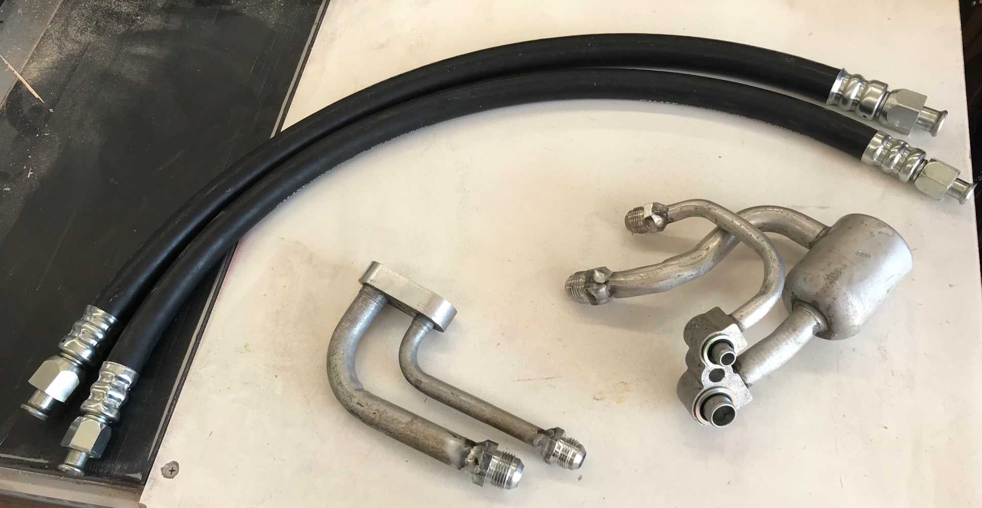
Mounting the LFX compressor is simple, it only goes in one place. There are no adjustments needed. The compressor hose connections look similar to those on the Fiero but are totally different. The LFX compressor pipes were part of the hose assembly which was totally incompatible with the space available. I used my local hose experts at House of Hose in Spokane, WA to make me up a pair of custom hoses that would connect to the Impala compressor fittings using compression connectors and then connect the other ends similarly to the Fiero original hose fittings. Oh, and I'm not sure how long to make each hose so don't crimp the Fiero ends until I get a final measurement. So they did what I told them to do and moved the Impala fittings (per my rough sketches) to try and clear the alternator.
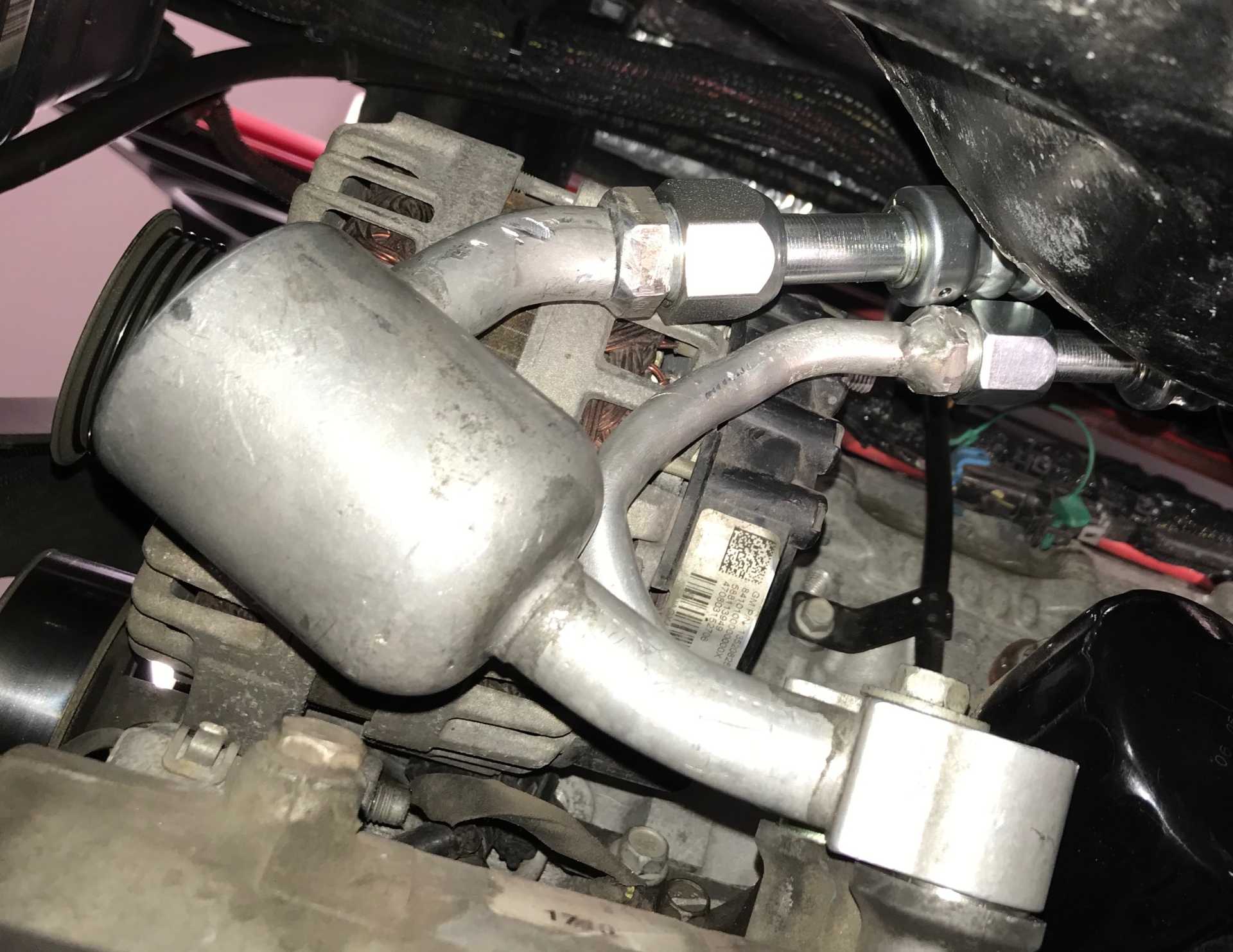
About a week later they delivered the parts. The first problem was the Impala compressor block would not clear the alternator. I got out the torch and bent them until they did clear everything. Connected up the Impala ends and routed the hoses to the Fiero hose ends. Then cable-tied it all up so the hose lengths were determined and the fittings could be crimped on. And by-the-way could you please take a kink I made out of the Impala pipe? The results were great, everything fit correctly but it leaked badly at the Fiero connection to the firewall. That took some new A/C rated washers and two attempts to get it right. When evacuated, charged and checked for leaks it worked with only a partial charge in the system. So load it up with the 20 ounces of refrigerant and I've got cold air. Total cost of the custom hoses was about $350 with tax.
Here are the hoses and the two end connectors to the Fiero and the Compressor
Installed hose connections looking up at engine, Compressor at bottom, Clears the alternator and hoses run over to the driver side.
 [This message has been edited by MikesFirstFiero (edited 01-26-2024).]
|
|
|
|
MikesFirstFiero
|
JAN 26, 03:29 PM
|
|
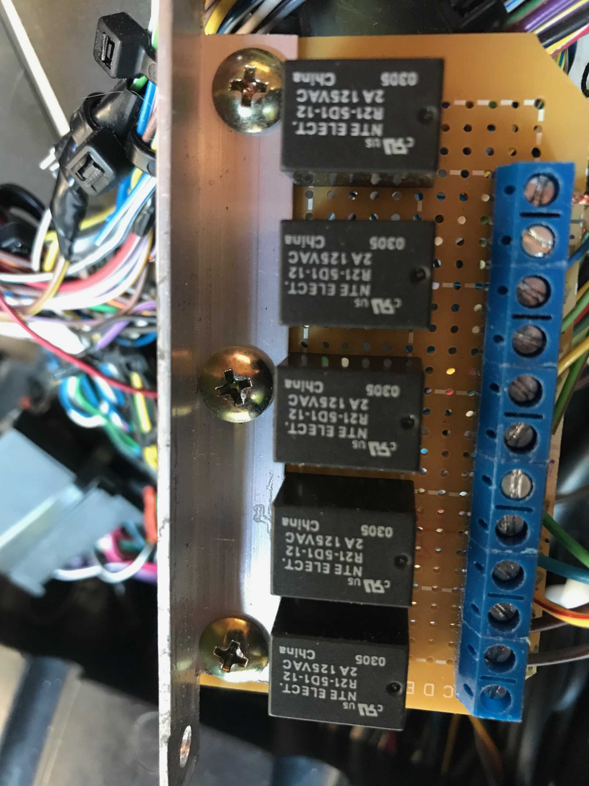
Now that the A/C is working I decided to tackle a minor issue with the Impala instrument cluster. The indicators for turn signals, lights on and high beams don't work. Those indicators are operated by data fron the Body Control Module. Swell, lets just hook them up. Uh, might need to read the shop manuals first and confirm how they operate. The Fiero harness brings the signals high (+12V) when active and low when off. Digging in the Impala documentation the BCM expects these signals to be driven low when active. Well that sucks. The simplest solution is to make a small relay PCB with inputs from the Fiero driving the relay coils, then use a normally open contact on each relay to connect to the BCM signals. I guess I could have used some kind of transistor or FET circuit to do this but relays are simple and isolate the Fireo from the Impala.
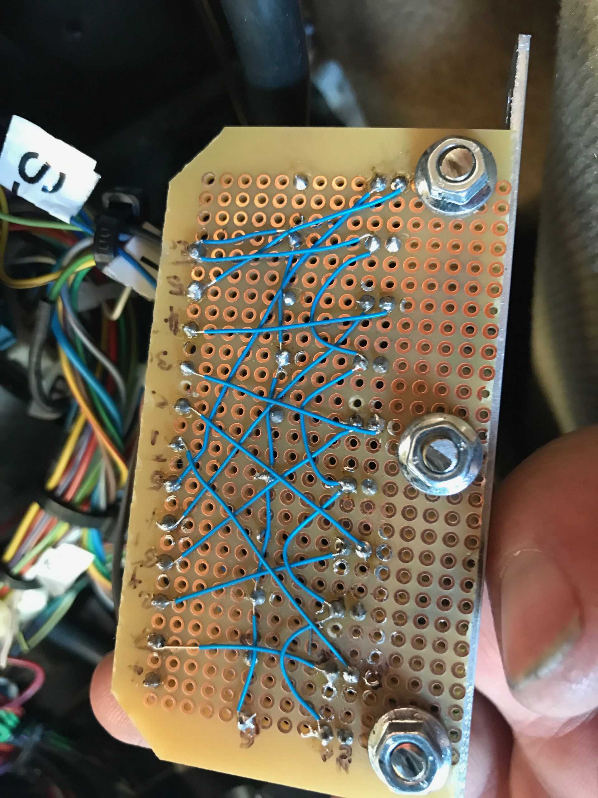
Here is the PCB, Hand wired. It lives in the center console next to the BCM. I built it with 5 relays in case I needed to add a fifth circuit
The back is #28 Kynar insulated wire I had laying around.
And it works! With some side effects though. Seems that the Impala BCU always turns on the daylight running lamps so the lights on indicator is always present. The high beam indicator does work eecept it will be off when the lights are first turned on. Once cycled High/Low it then works.
The turn signal indicators also work correctly without fail. But... Always a "but" it seems, the LCD display in the cluster sometimes says "Left (or Right) Turn Signal Lamp Failure". I'm guessing the BCM monitors the current to the Impala turn signal bulb, which does not exist. I might findt hose outputs and hook a resistor to each of them so the circuit can measure some current and not nag.
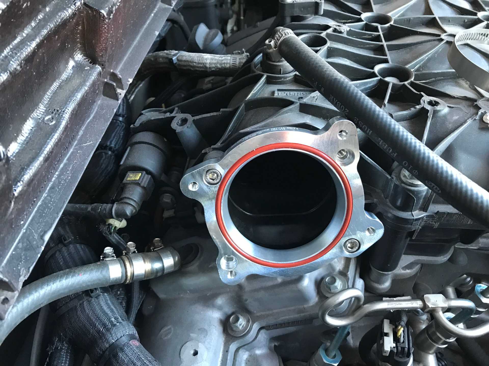
I took the car to a tuner recommended by one of my customers. Marty Stromberg has been tuning cars literally for decades in the Spokane area. I looked him up and found he has had several articles written about his work. Turns out he has a Camaro with the same LFX motor as I have So I had him do a first session of tuning to eliminate the anti-theft BS and do a first engine & transmission tune. While doing this he mentioned that the L89 throttle body was a bolt-on that increased the TB from 70 to 80mm. I dug around and found an adapter and the TB came from O'Reilly's.
The adapter mounted to the intake manifold. I did some port matching on it to match the manifold inlet.
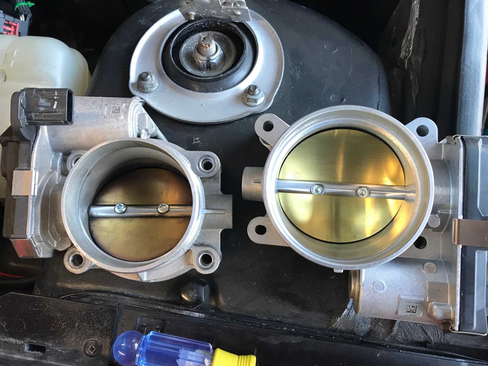
Here are the two TBs side by side. Bith have the same connector and wiring so no changes needed.
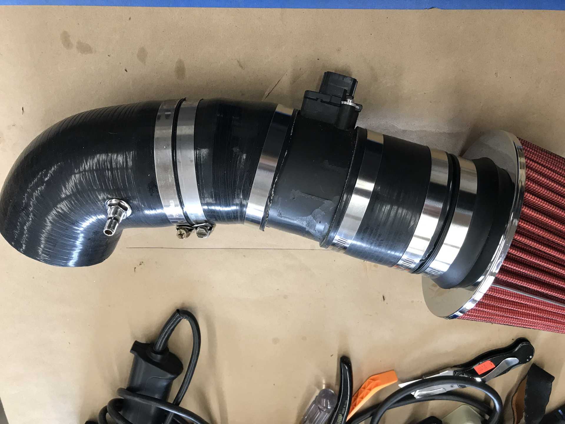
Then I rebuilt the intake to match the larger TB diameter with a tapered hose. I'll do more on it later on.
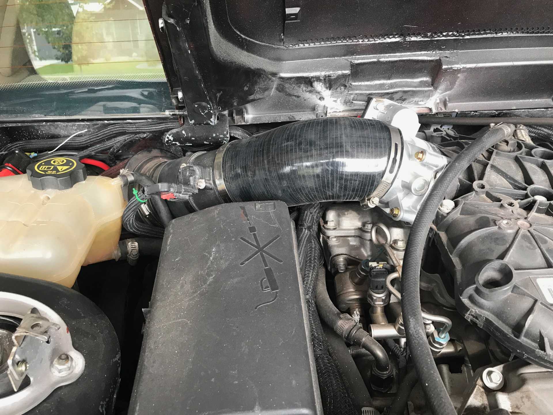
Naturally this made the engine not happy so I planned to re-visit Marty and I found the parts to make the intake 4" end to end.
Back side view of intake
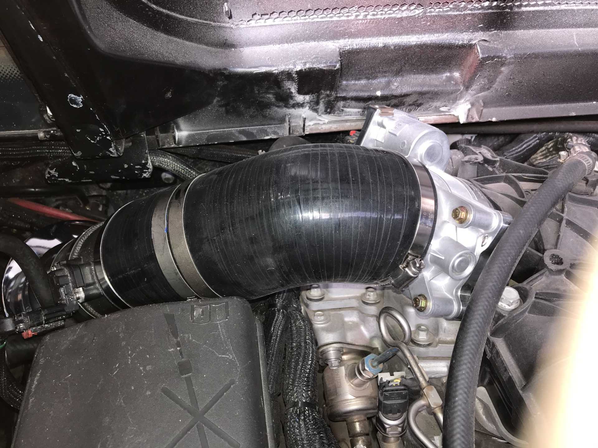
It's a bit tight here
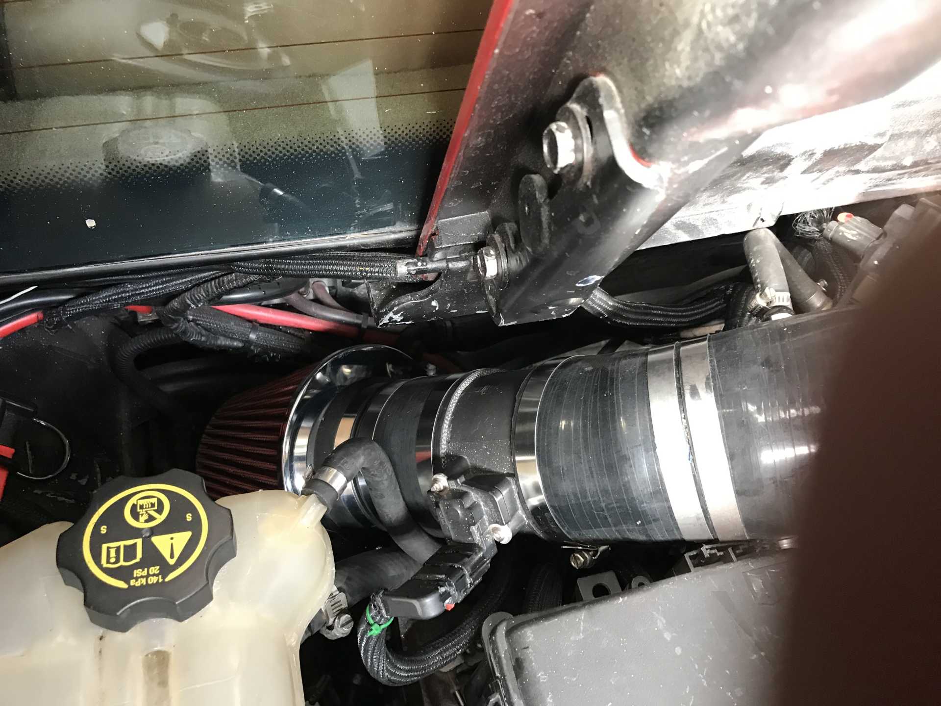
But this end is good. Did need to increase the deck notch a bit to clear the TB connector
|
|
|
|
MikesFirstFiero
|
JAN 27, 03:10 PM
|
|
Putting the larger TB did not do too much for the performance and actually made normal driving much worse. Engine response when the transmission shifted was very laggy. I expected it would need a re-tune and scheduled another session with Marty. I asked him to focus on improving the engine performance and not worry about some shifting issues until the spring. He came through and made the performance improve under all conditions and improved shifting also. I did a quick quarter mile run and it looks like I'm now at 0-60 in 5.1, 1/4 in 13.8 at 104. I need to do more test runs but with the winter weather that will wait for the spring too.
And then a problem appeared. I noticed some A/T fluid leaking at the radiator connection, seems like the fitting was cross-threaded when installed years ago. I looked into getting a replacement radiator with an internal A/T cooler and discovered most of them have plastic end caps, including the ones O'Reilly sells. Don't want that so I found a link to a guy who put in an all-aluminum Griffen radiator with minimal mods to the car. So the oil cooler would now be external. I sourced one and figured the best place to mount an external cooler was under the driver side cooling vent. This puts it directly above the transmission and in a place where upflow air will cool it.
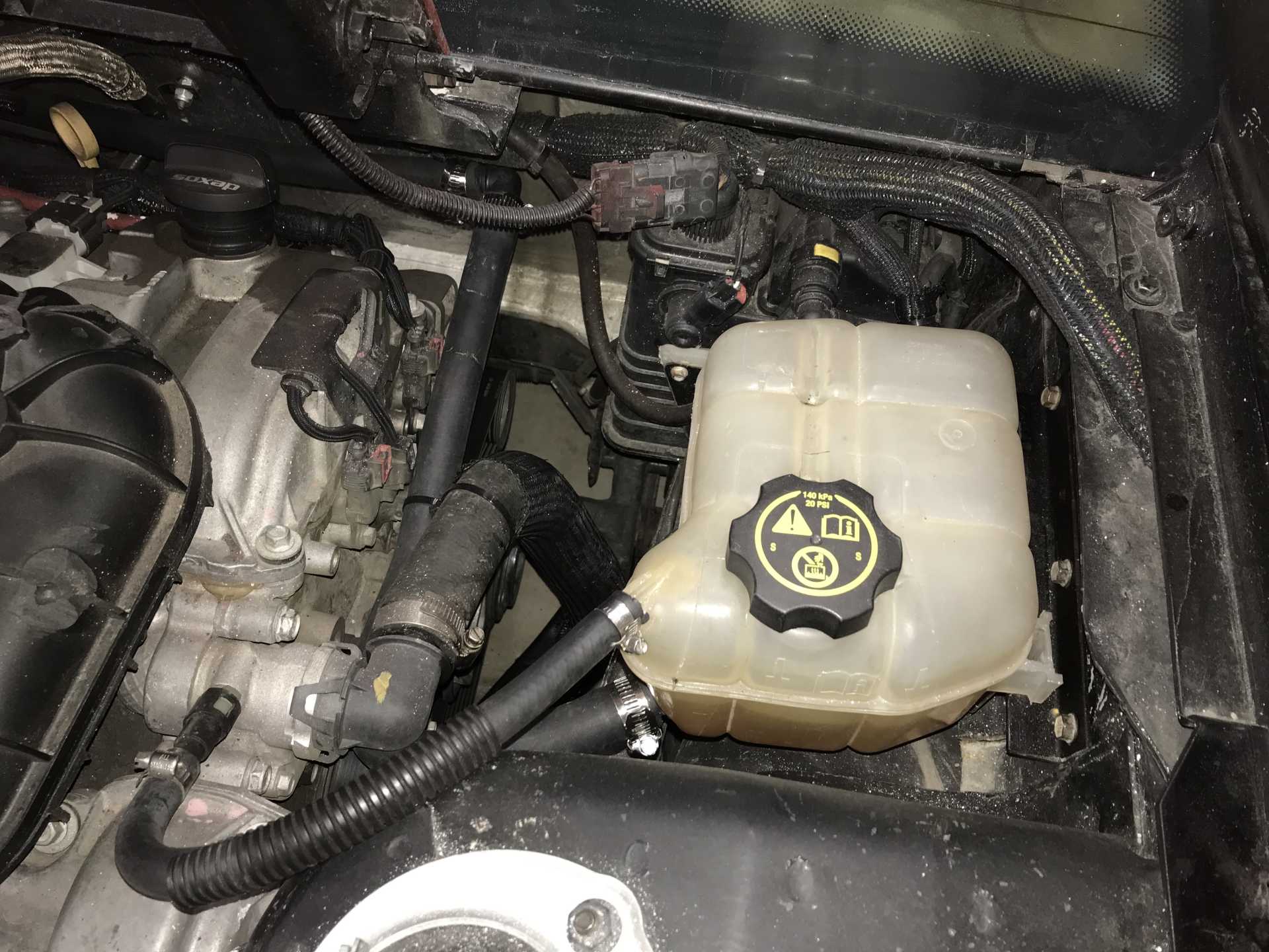
In order to put it there I needed to move the cooling overflow tank to the passenger side, this had several positive effects. The driver side now has room to fit the new A/T cooler; has more room to accommidate the engine air intake; makes working on that area much simpler with more room to access parts and removes a visible cooling hose from the rear of the engine. The passenger side had a big unused space where the coolant tank fit nicely. At the same time I noticed coolant was escaping to the front coolant overflow tank when I lifted the rear end of the car to crawl under. This drained coolant into the front overflow tank and lowered the coolant level in the engine and Impala overlow tank. I decided to seal the front radiator cap and then remove the Fiero overflow tank. After all the Impala had only the one overflow tank with a direct hose from the engine high point to burp air out of the system. I cut a piece of 1/8" hard rubber sheet to fit in the radiator neck and block the radiator cap. By adding it the pressure needed to release the radiator cap was higher than the pressure to release the Impala cap in the back. I then removed the Fiero overflow tank. Problem solved at no cost.
Location of the new A/T cooler
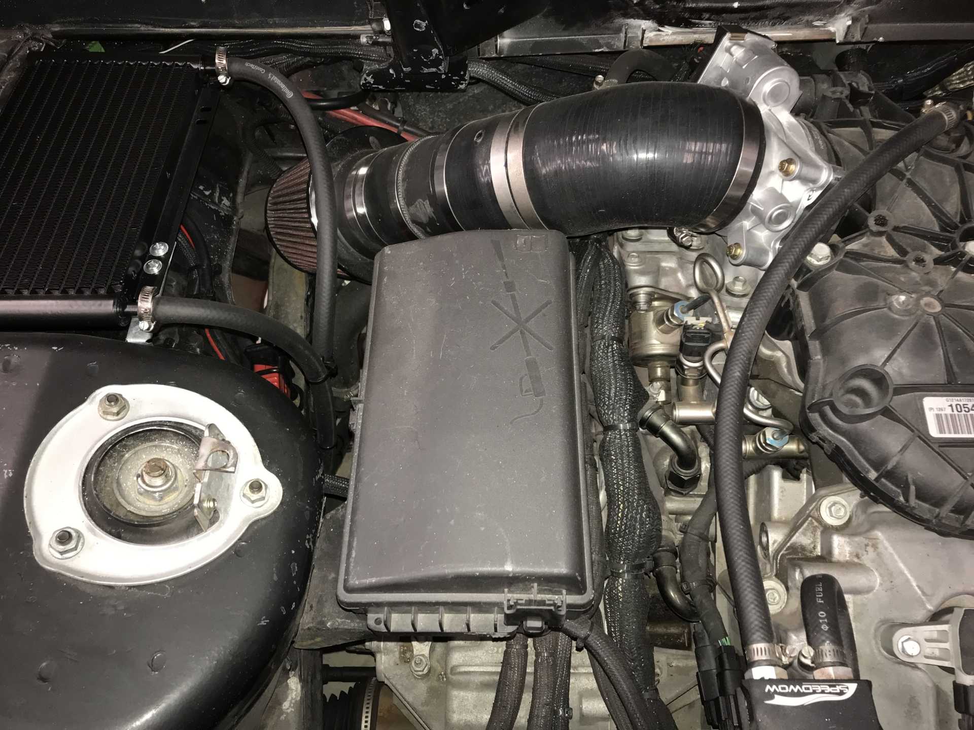
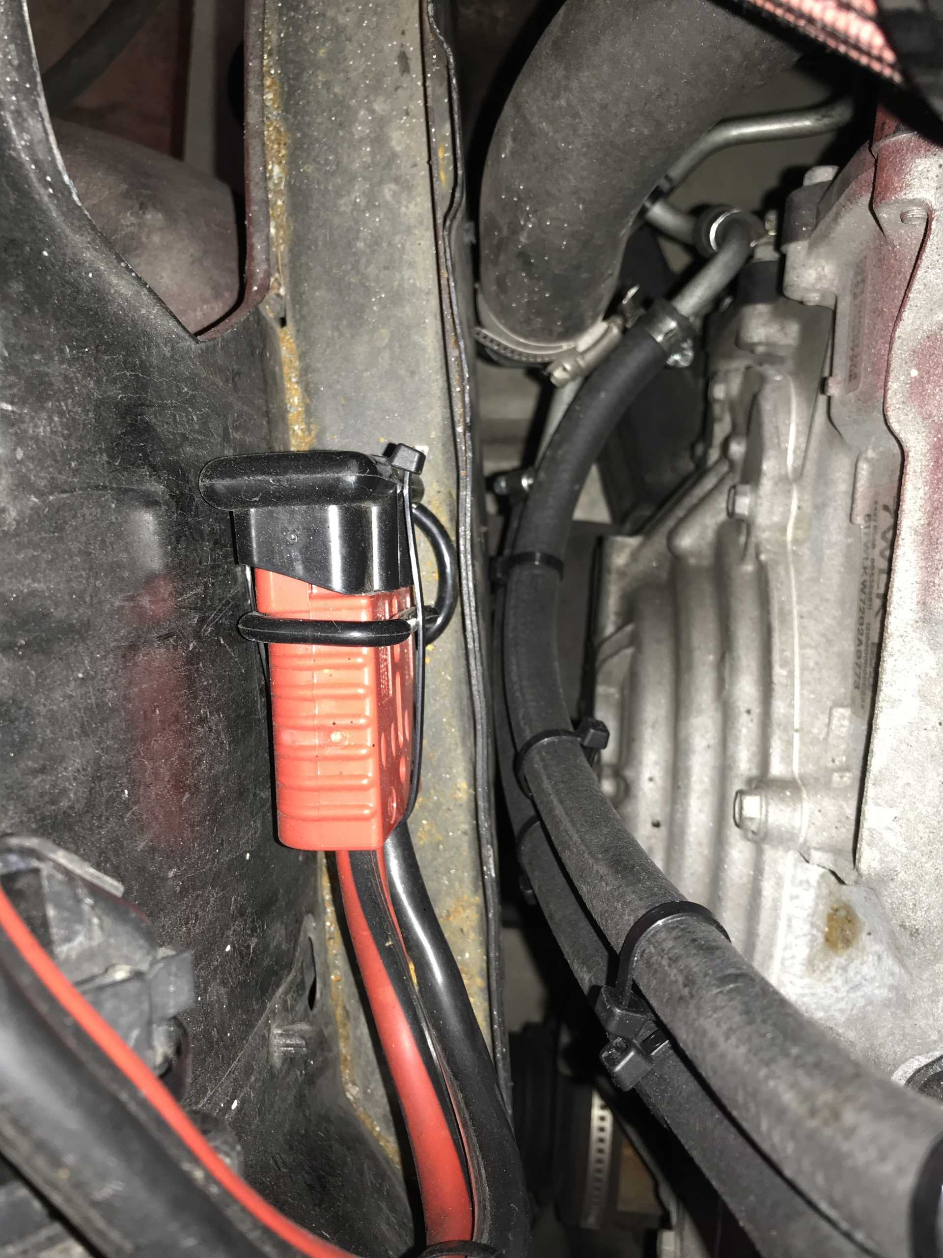
Hoses connecting to the transmission are just below it. Red connector on the left is for my jump-start cables, Getting to the side-post battery in front is difficult. My jumper cables have a mating connector on one end and normal clamp connectors on the other. If you want real copper jumper cables expect to spend at least $80 or more.
This hose is now deleted
So it looks like this now
And the tank is now on the right side, The missing hose now runs ahead of the motor.
I also found a source of some vibration while crawling under the car. There was a exhaust clamp bolt touching the edge of the trunk. Cut it off with an angle grinder and the vibration is lower than before.
|
|
|
|
Will
|
JAN 27, 07:25 PM
|
|
| quote | Originally posted by MikesFirstFiero:
In order to put it there I needed to move the cooling overflow tank to the passenger side, this had several positive effects. The driver side now has room to fit the new A/T cooler; has more room to accommidate the engine air intake; makes working on that area much simpler with more room to access parts and removes a visible cooling hose from the rear of the engine. The passenger side had a big unused space where the coolant tank fit nicely. At the same time I noticed coolant was escaping to the front coolant overflow tank when I lifted the rear end of the car to crawl under. This drained coolant into the front overflow tank and lowered the coolant level in the engine and Impala overlow tank. I decided to seal the front radiator cap and then remove the Fiero overflow tank. After all the Impala had only the one overflow tank with a direct hose from the engine high point to burp air out of the system. I cut a piece of 1/8" hard rubber sheet to fit in the radiator neck and block the radiator cap. By adding it the pressure needed to release the radiator cap was higher than the pressure to release the Impala cap in the back. I then removed the Fiero overflow tank. Problem solved at no cost.
|
|
Great that you're making progress on the car!
I'm not sure your cooling system mod will work out well. I've been able to get a Northstar to purge air by having a lower pressure cap at the back with a higher pressure cap at the front, while keeping the Fiero overflow tank at the front. Note that this purges air from one end, then refills coolant from the OPPOSITE end, keeping both ends topped up.
The Fiero system has TWO high points, while the Impala system only has one. That's a big difference.
If you run a LOWER pressure cap up front, then the system will purge air out the front cap. With the nipple capped off, it will not be able to pull in air from the front. You will see the level in the surge tank in the engine bay drop as the system purges air from the front. Then you just top up the surge tank.[This message has been edited by Will (edited 01-28-2024).]
|
|
|
|
Will
|
JAN 27, 07:38 PM
|
|
| quote | Originally posted by MikesFirstFiero:
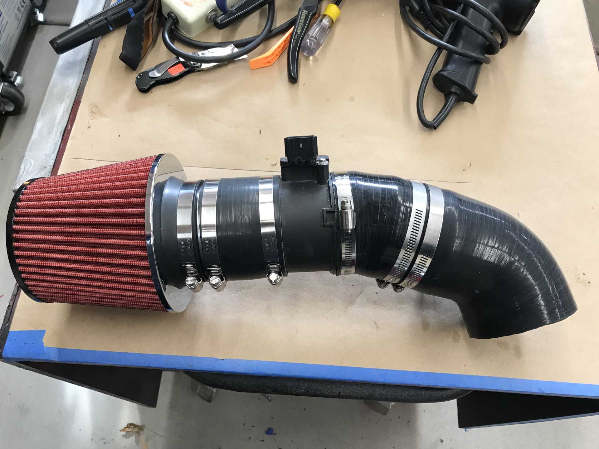
Naturally this made the engine not happy so I planned to re-visit Marty and I found the parts to make the intake 4" end to end.
Back side view of intake
|
|
What MAF is that?
|
|
|
|
MikesFirstFiero
|
JAN 29, 12:00 AM
|
|
As now configured the high point of the entire system is the Impala tank. The last photo shows the curved hose from the engine high point going into the tank at it's top (burp hose?). The feed from the tank to the engine is the hose from the tank bottom running forward to the firewall and then to the driver's side where it hooks up to the thermostat housing in the driver's side (picture in a earlier post). The radiator isn't near as high as the engine compartment tank. The front radiator cap was rated at 16PSI and the rear is 20PSI but the front now has the seal of rubber that blocks the suction operation ans would open only if the pressure exceeds more than 16 PSI. I'm not really sure what that pressure is since I haven't measured it yet. The Impala had only the one tank I used with a different philosophy from the overflow tanks of the past. I had been losing a slight amount of coolant but traced that to two hose clamps that were not very tight under the car. I'm keeping my eye on it to see if it works as needed.
In practical terms the old 2.8 was always difficult to keep cool. The Impala runs much cooler and has never shown any signs of overheating in 7,000 miles. I've disabled the radiator fan for the winter and won't need it until air conditioning season. That was a real surprise. Maybe since the LFX is more efficient and rejects less heat to the cooling system than the old engine did in normal city & highway driving.
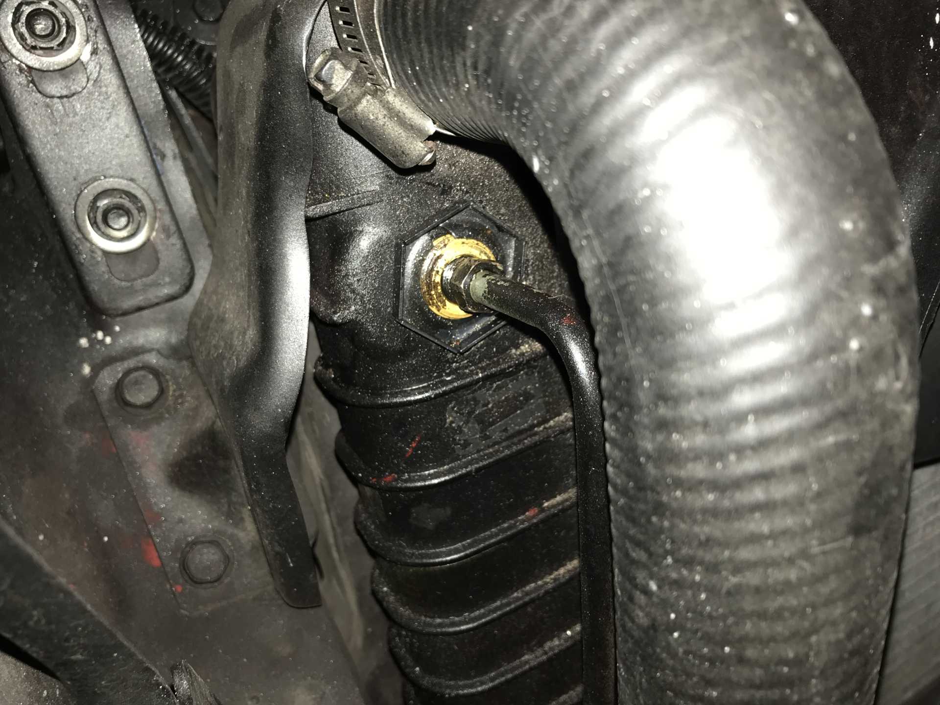
The MAF is the original Impala unit. I only shaved the OD of the housing to match the hoses on both ends. It keep things simple and reduce costs I've tried to use as much of the original Impala equipment as possible. And the valve stem on the hose is drilled out and provides metered air to the forward valve cover.[This message has been edited by MikesFirstFiero (edited 01-29-2024).]
|
|
|
|